EP0772038A2 - Verfahren und Vorrichtung zur optischen Messung durch Polarisationsanalyse - Google Patents
Verfahren und Vorrichtung zur optischen Messung durch Polarisationsanalyse Download PDFInfo
- Publication number
- EP0772038A2 EP0772038A2 EP96307850A EP96307850A EP0772038A2 EP 0772038 A2 EP0772038 A2 EP 0772038A2 EP 96307850 A EP96307850 A EP 96307850A EP 96307850 A EP96307850 A EP 96307850A EP 0772038 A2 EP0772038 A2 EP 0772038A2
- Authority
- EP
- European Patent Office
- Prior art keywords
- phase
- electric signal
- expanding
- light
- section
- Prior art date
- Legal status (The legal status is an assumption and is not a legal conclusion. Google has not performed a legal analysis and makes no representation as to the accuracy of the status listed.)
- Granted
Links
Images



Classifications
-
- G—PHYSICS
- G01—MEASURING; TESTING
- G01N—INVESTIGATING OR ANALYSING MATERIALS BY DETERMINING THEIR CHEMICAL OR PHYSICAL PROPERTIES
- G01N21/00—Investigating or analysing materials by the use of optical means, i.e. using sub-millimetre waves, infrared, visible or ultraviolet light
- G01N21/17—Systems in which incident light is modified in accordance with the properties of the material investigated
- G01N21/21—Polarisation-affecting properties
Definitions
- the present invention relates to an optical measuring apparatus for measuring the physical amount of a specific component contained in a substance to be measured, and a method employed by such an apparatus.
- the physical amounts include, for example, the displacement of an object, the surface profile of an object, the birefringence of a substance having the birefringence property, and the concentration of an aqueous solution of a substance having a rotatory power.
- the method utilizes the fact that a relationship exists between the phase of heterodyning interference light and the physical amount of a specific component which is an object of the measurement.
- the method includes converting the interference light into an electric signal and determining the physical amount of the specific component by measuring the phase of the electric signal.
- the physical amount is determined by measuring a shift in the phase of the measurement light from the phase of a known reference light (i.e., the phase difference between the reference light and the measurement light).
- phase difference between the reference light and the measurement light is affected by the change in the physical amount to be measured. As the change in the physical amount becomes larger, the phase difference becomes larger.
- the phase difference is normally extremely small, however. A phase difference meter with extremely high precision is therefore required to measure the change in the physical amount with high resolution and high precision.
- the limit of the resolution of a phase difference meter is generally 0.1° to 0.01° electrically. A phase difference below the above limit cannot be measured. It is not possible, therefore, to measure a minute change in the physical amount by the conventional method.
- the optical measuring apparatus of this invention for measuring a physical amount of a specific component contained in a substance to be measured by the use of measurement light which passes through the substance to be measured and the use of predetermined reference light includes: a first interfering means for obtaining a first light interference signal by interfering the measurement light; a second interfering means for obtaining a second light interference signal by interfering the reference light; a first photoelectric converting section for converting the first light interference signal into a first electric signal; a second photoelectric converting section for converting the second light interference signal into a second electric signal; a first phase expanding section for expanding a phase of the first electric signal; a second phase expanding section for expanding a phase of the second electric signal; a phase difference measuring section for measuring a phase difference between a phase expanded by the first phase expanding section and a phase expanded by the second phase expanding section; and a physical amount determining section for determining the physical amount of the specific component contained in the substance to be measured depending on the phase difference measured by the phase difference measuring section.
- the reference light passes through a reference substance.
- the first phase expanding section includes at least one first multiplying circuit for multiplying the first electric signal
- the second phase expanding section includes at least one second multiplying circuit for multiplying the second electric signal
- the first multiplying circuit includes a first multiplier for expanding a frequency and a phase of the first electric signal, a first amplifier for amplifying an output of the first multiplier, and a first waveform processor for extracting a signal having a predetermined frequency from an output of the first amplifier to remove noise
- the second multiplying circuit includes a second multiplier for expanding a frequency and a phase of the second electric signal, the second amplifier for amplifying an output of the second multiplier, and a second waveform processor for extracting a signal having a predetermined frequency from an output of the second amplifier to remove noise.
- an optical measuring method for measuring a physical amount of a specific component contained in a substance to be measured by the use of measurement light which passes through the substance to be measured and the use of predetermined reference light.
- the method includes the steps of: a) obtaining a first light interference signal by interfering the measurement light; b) obtaining a second light interference signal by interfering the reference light; c) converting the first light interference signal into a first electric signal; d) converting the second light interference signal into a second electric signal; e) expanding a phase of the first electric signal; f) expanding a phase of the second electric signal; g) measuring a phase difference between a phase expanded at step e) and a phase expanded at step f); and h) determining the physical amount of the specific component contained in the substance to be measured depending on the phase difference measured at step g).
- the reference light passes through a reference substance.
- the step e) comprises the step of: i) multiplying the first electric signal at least once
- the step f) comprises the step of: j) multiplying the second electric signal at least once.
- the step i) comprises the steps of: expanding a frequency and a phase of the first electric signal by use of a first multiplier; amplifying an output of the first multiplier by use of a first amplifier; and extracting a signal having a predetermined frequency from an output of the first amplifier to remove noise
- the step j) comprises the steps of: expanding a frequency and a phase of the second electric signal by use of a second multiplier; amplifying an output of the second multiplier by use of a second amplifier; and extracting a signal having a predetermined frequency from an output of the second amplifier to remove noise.
- the invention described herein makes possible the advantages of (1) providing an optical measuring apparatus with an improved measuring precision capable of measuring a minute change in a physical amount, and (2) providing an optical measuring method employed by such an apparatus.
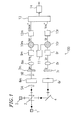
- Figure 1 illustrates a configuration of an optical measuring apparatus according to the present invention.
- Figure 2 illustrates configurations of phase expanding sections for measurement light and reference light of the apparatus.
- Figure 3 illustrates configurations of multiplying circuits for measurement light and reference light of the phase expanding sections of the apparatus.
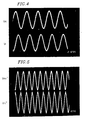
- Figure 4 illustrates waveforms of signals input into the multiplying circuits for measurement light and reference light.
- Figure 5 illustrates waveforms of signals output from the multiplying circuits for measurement light and reference light.
- Figure 6 is a graph showing the relationship between the phase difference between the signals input into the phase expanding sections and the phase difference between the output signals output from the phase expanding sections.
- FIG. 1 illustrates a configuration of an optical measuring apparatus 100 according to the present invention.
- the optical measuring apparatus 100 includes light sources 1 and 2 , a beam splitter 3 , a mirror 4 , sample cells 6m and 6r , polarizing plates 7m and 7r , photodiodes 8m and 8r , amplifiers 9m and 9r , mixers 10m and 10r , an electric signal oscillator 11 , phase expanding sections 12m and 12r , a phase difference meter 13 , and a physical amount determining section 14 .
- the light sources 1 and 2 emit beams of light.
- a beam emitted from the light source 1 and a beam emitted from the light source 2 have frequencies different from each other, and are polarized in directions apart from each other by 90°.
- the light source 1 emits a beam with a frequency f 0 polarized in the horizontal direction
- the light source 2 emits a beam with a frequency f 0 + ⁇ f polarized in the vertical direction.
- the beams emitted from the light sources 1 and 2 are incident on the beam splitter 3 .
- the beam splitter 3 splits the beams from the light sources 1 and 2 into measurement light and reference light.
- the resultant measurement light and reference light respectively include a horizontally linearly polarized light component with a frequency f 0 and a vertically linearly polarized light component with a frequency f 0 + ⁇ f. These linearly polarized light components are coherent components.
- the sample cell 6m , the polarizing plate 7m , and the photodiode 8m are disposed on the optical path for the measurement light output from the beam splitter 3 .
- the measurement light passes through the sample cell 6m which stores a substance to be measured.
- the measurement light then passes through the polarizing plate 7m , where the horizontally linearly polarized light component and the vertically linearly polarized light component are superimposed on each other to interfere with each other.
- a light interference signal I m with a frequency ⁇ f and a phase ⁇ m is obtained as the output of the polarizing plate 7m .
- the phase ⁇ m depends both on the phase difference between the horizontally linearly polarized light component and the vertically linearly polarized light component and a phase difference caused by the nature of the substance to be measured.
- 1/4 wave plates 5A and 5B are additionally disposed on the optical path for the measurement light as shown in Figure 1 .
- the polarizing state of the beam changes.
- the 1/4 wave plate is disposed so that the axis thereof is 45° with respect to the plane of vibration of the linearly polarized light component
- the linearly polarized light component is converted into a circularly polarized light component by the 1/4 wave plate.
- a circularly polarized light component is converted into a linearly polarized light component by the 1/4 wave plate.
- the horizontally linearly polarized light component and the vertically linearly polarized light component included in the measurement light output from the beam splitter 3 are converted into a clockwise circularly polarized light component and a counterclockwise circularly polarized light component, respectively.
- the measurement light passes through the sample cell 6m .
- the phases of the clockwise circularly polarized light component and counterclockwise circularly polarized light component shift from each other.
- the clockwise circularly polarized light component and the counterclockwise circularly polarized light component then pass through the 1/4 wave plate 5B to be converted back into the horizontally linearly polarized light component and the vertically linearly polarized light component, respectively.
- the measurement light then passes through the polarizing plate 7m .
- the reference light output from the beam splitter 3 is reflected by the mirror 4 , changing the direction by 90°.
- the sample cell 6r , the polarizing plate 7r , and the photodiode 8r are disposed on the optical path for the reference light reflected by the mirror 4 .
- the reference light output from the beam splitter 3 passes through the sample cell 6r which stores no substance to be measured. Then, the reference light passes through the polarizing plate 7r , where the horizontally linearly polarized light component and the vertically linearly polarized light component are superimposed with each other to interfere each other. As a result, a light interference signal I r with a frequency ⁇ f and a phase ⁇ r is obtained as an output of the polarizing plate 7r .
- the phase ⁇ r depends on the phase difference between the horizontally linearly polarized light component and the vertically linearly polarized light component.
- the photodiode 8m converts the light interference signal I m into an electric signal V m
- the photodiode 8r converts the light interference signal I r into an electric signal V r .
- V m and V r are represented by expressions (3) and (4) below, respectively:
- V m B m •Sin[ ⁇ t+ ⁇ m ]
- V r B r •Sin[ ⁇ t+ ⁇ r ]
- B m and B r denote the amplitude of the electric signals V m and V r , respectively.
- the electric signal V m is amplified by the amplifier 9m and then mixed with an oscillated electric signal output from the electric signal oscillator 11 by the mixer 10m so as to obtain a frequency range measurable by the phase difference meter 13 .
- the output of the mixer 10m is supplied to the phase expanding section 12m .
- the electric signal V r is supplied to the phase expanding section 12r via the amplifier 9r and the mixer 10r .
- FIG. 2 illustrates configurations of the phase expanding sections 12m and 12r .
- the phase expanding section 12m includes N multiplying circuits 120m-1 to 120m-N which are connected in series.
- the phase expanding section 12r includes N multiplying circuits 120r-1 to 120r-N which are connected in series.
- Figure 3 illustrates configurations of the multiplying circuits 120m-1 and 120r-1 .
- the multiplying circuit 120m-1 includes a multiplier 121m-1 , an amplifier 122m-1 , and a waveform processor 123m-1 .
- the multiplying circuit 120r-1 includes a multiplier 121r-1 , an amplifier 122r-1 , and a waveform processor 123r-1 .
- the multiplier 121m-1 multiplies the electric signal V m output from the mixer 10m by itself so as to expand the frequecncy and the phase of the electric signal V m . As a result, an electric signal V m1 ' is obtained.
- the electric signal V m1 ' is represented by expression (6) below: wherein D m denotes the amplitude of the electric signal V m1 ' and ⁇ m denotes the phase of the electric signal V m1 '.
- the multiplier 121r-1 multiplies the electric signal V r output from the mixer 10r by itself so as to expand the frequency and the phase of the electric signal V r .
- an electric signal V r1 ' is obtained.
- the electric signal V r1 ' is represented by expression (6) below: wherein D r denotes the amplitude of the electric signal V r1 ' and ⁇ r denotes the phase of the electric signal V r1 '.
- the amplifier 122m-1 amplifies the electric signal output from the multiplier 121m-1 so that the amplitude of the signal attenuated by the frequency expansion processing by the multiplier 121m-1 is compensated to resume the original amplitude.
- the waveform processor 123m-1 extracts a required frequency from the electric signal to remove noise and outputs an electric signal V m1 ".
- V m1 " D m1 •Cos(2 ⁇ t+2 ⁇ m )
- the electric signal V m1 " is output from the multiplying circuit 120m-1.
- the configurations of the multiplying circuits 120m-2 to 120m-N are the same as that of the multiplying circuit 120m-1 .
- V rN " D rN •Cos(2 N ⁇ t+2 N ⁇ r )
- the phase difference ⁇ N is measured by the phase difference meter 13 .
- the phase difference ⁇ N and the physical amount of a specific component contained in the substance to be measured has a predetermined relationship.
- the physical amount of the specific component is defined as a function F of the phase difference ⁇ N .
- the function F is given.
- the physical amount determining section 14 determines the physical amount based on the phase difference ⁇ N .
- the physical amounts include, for example, the displacement of an object, the surface profile of an object, the birefringence of a substance having the birefringence property, and the concentration of an aqueous solution of a substance having a rotatory power.
- Figure 4 shows waveforms of the electric signal V m corresponding to the measurement light and the electric signal V r corresponding to the reference light both obtained before the phase expansion by the multiplying circuit 120m-1 and 120r-1 . These waveforms can be observed by use of an oscilloscope.
- Figure 5 shows waveforms of the electric signal V m1 " corresponding to the measurement light and the electric signal V r1 " corresponding to the reference light both obtained after the phase expansion by the multiplying circuit 120m-1 and 120r-1 . These waveforms can be observed by use of an oscilloscope.
- phase difference between the electric signal V m corresponding to the measurement light and the electric signal V r corresponding to the reference light is 90° in Figure 4
- the phase difference between the electric signal V m1 " corresponding to the measurement light and the electric signal V r1 " corresponding to the reference light has been expanded to 180° in Figure 5 .
- Figure 6 shows the relationship between the phase difference between the signals input into the phase expanding sections 12m and 12r and the phase difference between the signals output from the phase expanding sections 12m and 12r . It is found from Figure 6 that the phase difference has been expanded by the phase expanding sections 12m and 12r .
- the sample cell 6r may store a reference substance to allow the reference light to pass through the reference substance.
- the reference substance may be the air, for example.
- the inside of the sample cell 6r may be vacuum.
- Mixers may be used as the multipliers.
- Filters such as a band-pass filter and a high-pass filter may be used as the waveform processors.
- a mixer may be used to decrease the frequency of the electric signal after the increase of the frequency by the multiplier. This facilitates the measurement of the phase difference.
- the phase of a first electric signal corresponding to the measurement light and that of a second electric signal corresponding to the reference light are expanded. This expands the phase difference between the first electric signal and the second electric signal.
- the precision of the measurement of the phase difference improves. Since the phase difference and the physical amount are in a predetermined relationship, the precision of the measurement of the physical amount also improves.
Landscapes
- Physics & Mathematics (AREA)
- Health & Medical Sciences (AREA)
- Life Sciences & Earth Sciences (AREA)
- Chemical & Material Sciences (AREA)
- Analytical Chemistry (AREA)
- Biochemistry (AREA)
- General Health & Medical Sciences (AREA)
- General Physics & Mathematics (AREA)
- Immunology (AREA)
- Pathology (AREA)
- Investigating Or Analysing Materials By Optical Means (AREA)
Applications Claiming Priority (3)
| Application Number | Priority Date | Filing Date | Title |
|---|---|---|---|
| JP31944295 | 1995-10-31 | ||
| JP31944295 | 1995-10-31 | ||
| JP319442/95 | 1995-10-31 |
Publications (3)
| Publication Number | Publication Date |
|---|---|
| EP0772038A2 true EP0772038A2 (de) | 1997-05-07 |
| EP0772038A3 EP0772038A3 (de) | 1998-09-16 |
| EP0772038B1 EP0772038B1 (de) | 2004-09-08 |
Family
ID=18110252
Family Applications (1)
| Application Number | Title | Priority Date | Filing Date |
|---|---|---|---|
| EP96307850A Expired - Lifetime EP0772038B1 (de) | 1995-10-31 | 1996-10-30 | Verfahren und Vorrichtung zur optischen Messung durch Polarisationsanalyse |
Country Status (4)
| Country | Link |
|---|---|
| US (1) | US5796482A (de) |
| EP (1) | EP0772038B1 (de) |
| CN (1) | CN1102237C (de) |
| DE (1) | DE69633322T2 (de) |
Families Citing this family (5)
| Publication number | Priority date | Publication date | Assignee | Title |
|---|---|---|---|---|
| KR100468155B1 (ko) * | 2002-06-27 | 2005-01-26 | 한국과학기술원 | 이종모드 헬륨-네온 레이저와 슈퍼 헤테로다인위상측정법을 이용한 헤테로다인 레이저 간섭계 |
| SE526267C2 (sv) * | 2003-12-05 | 2005-08-09 | Alfa Exx Ab | Optisk mätanordning |
| TWI407792B (zh) * | 2005-04-01 | 2013-09-01 | That Corp | 用於處理電視音頻信號之編碼器及解碼器 |
| CN103292914B (zh) * | 2013-05-11 | 2015-10-07 | 哈尔滨工业大学 | 基于双频激光无偏分光的光电接收器时间稳定性测试方法 |
| JP2017227512A (ja) * | 2016-06-21 | 2017-12-28 | 株式会社島津製作所 | 偏光測定装置 |
Family Cites Families (8)
| Publication number | Priority date | Publication date | Assignee | Title |
|---|---|---|---|---|
| US3510665A (en) * | 1967-07-12 | 1970-05-05 | Reynolds Metals Co | Apparatus for plasma measurement |
| FR2381300A1 (fr) * | 1977-02-21 | 1978-09-15 | France Etat | Photo-elasticimetre dynamique a birefringent tournant |
| JPS5764171A (en) * | 1980-10-08 | 1982-04-19 | Advantest Corp | Spectrum analyzer |
| IT1155285B (it) * | 1982-02-10 | 1987-01-28 | Cselt Centro Studi Lab Telecom | Procedimento e apparecchiatura per la determinazione del profilo d'indice di rifrazione di fibre ottiche e preforme per fibre ottiche |
| US4842408A (en) * | 1986-05-09 | 1989-06-27 | Canon Kabushiki Kaisha | Phase shift measuring apparatus utilizing optical meterodyne techniques |
| EP0567701B1 (de) * | 1992-04-27 | 1998-01-14 | Canon Kabushiki Kaisha | Verfahren und Gerät zur Inspektion |
| DE69333642T2 (de) * | 1992-07-31 | 2005-10-06 | Fuji Photo Film Co., Ltd., Minami-Ashigara | Verfahren und Vorrichtung zur Gewinnung dreidimensionaler Information von Proben |
| US5325172A (en) * | 1993-01-13 | 1994-06-28 | Hitachi Koki Company Limited | Optical system for analyzing samples separated by a centrifugal separator |
-
1996
- 1996-10-30 DE DE69633322T patent/DE69633322T2/de not_active Expired - Lifetime
- 1996-10-30 US US08/741,261 patent/US5796482A/en not_active Expired - Lifetime
- 1996-10-30 EP EP96307850A patent/EP0772038B1/de not_active Expired - Lifetime
- 1996-10-31 CN CN96120513.XA patent/CN1102237C/zh not_active Expired - Fee Related
Non-Patent Citations (1)
| Title |
|---|
| None |
Also Published As
| Publication number | Publication date |
|---|---|
| US5796482A (en) | 1998-08-18 |
| CN1102237C (zh) | 2003-02-26 |
| CN1154472A (zh) | 1997-07-16 |
| DE69633322T2 (de) | 2005-09-22 |
| EP0772038A3 (de) | 1998-09-16 |
| EP0772038B1 (de) | 2004-09-08 |
| DE69633322D1 (de) | 2004-10-14 |
Similar Documents
| Publication | Publication Date | Title |
|---|---|---|
| JP3273501B2 (ja) | 測定経路内のガスの屈折率の変動を測定する装置及び方法 | |
| US4633715A (en) | Laser heterodyne interferometric method and system for measuring ultrasonic displacements | |
| US5080491A (en) | Laser optical ultarasound detection using two interferometer systems | |
| US4193690A (en) | Heterodyne detection of coherent Raman signals | |
| US5663793A (en) | Homodyne interferometric receiver and calibration method having improved accuracy and functionality | |
| US6018391A (en) | Method and apparatus for inspecting foreign matter by examining frequency differences between probing light beam and reference light beam | |
| KR20000068090A (ko) | 슈퍼헤테로다인 간섭계 및 전자 주파수 증배를 사용하여 공기의굴절률을 보상하기 위한 방법 | |
| CN111829981B (zh) | 一种基于tdlas的气体外差检测装置及检测方法 | |
| JPH07311182A (ja) | 光熱変位計測による試料評価方法 | |
| US5298970A (en) | Sample evaluating method by using thermal expansion displacement | |
| EP0772038B1 (de) | Verfahren und Vorrichtung zur optischen Messung durch Polarisationsanalyse | |
| US7126695B2 (en) | Heterodyne frequency modulated signal demodulator and method of operating the same | |
| JP3662370B2 (ja) | 光学式測定装置および方法 | |
| JPH08278202A (ja) | 偏光解析用光学系装置及びこれを用いた偏光解析装置 | |
| JP3361896B2 (ja) | レーザドプラ方式振動計 | |
| JP3626907B2 (ja) | 干渉測定方法および装置 | |
| WO1998008047A1 (en) | Superheterodyne method and apparatus for measuring the refractive index of air using multiple-pass interferometry | |
| JP2806131B2 (ja) | 超音波の非接触検出方法及びその装置 | |
| GB1605217A (en) | Laser probe for detecting movement of a target | |
| Chambon et al. | High frequency optical probe for BAW/SAW devices | |
| RU2340879C1 (ru) | Устройство измерения параметров поляризации оптического излучения | |
| JPH0682086B2 (ja) | モ−ド結合評価装置 | |
| Ho et al. | Direct and indirect dual-probe interferometers for accurate surface wave measurements | |
| JP3795657B2 (ja) | ヘテロダイン偏光による異物検査方法及びこの方法を実施する装置 | |
| RU2028626C1 (ru) | Устройство для измерения частоты гармонических электрических колебаний |
Legal Events
| Date | Code | Title | Description |
|---|---|---|---|
| PUAI | Public reference made under article 153(3) epc to a published international application that has entered the european phase |
Free format text: ORIGINAL CODE: 0009012 |
|
| AK | Designated contracting states |
Kind code of ref document: A2 Designated state(s): DE FR GB IT |
|
| PUAL | Search report despatched |
Free format text: ORIGINAL CODE: 0009013 |
|
| AK | Designated contracting states |
Kind code of ref document: A3 Designated state(s): DE FR GB IT |
|
| 17P | Request for examination filed |
Effective date: 19990311 |
|
| GRAP | Despatch of communication of intention to grant a patent |
Free format text: ORIGINAL CODE: EPIDOSNIGR1 |
|
| GRAS | Grant fee paid |
Free format text: ORIGINAL CODE: EPIDOSNIGR3 |
|
| GRAA | (expected) grant |
Free format text: ORIGINAL CODE: 0009210 |
|
| AK | Designated contracting states |
Kind code of ref document: B1 Designated state(s): DE FR GB IT |
|
| REG | Reference to a national code |
Ref country code: GB Ref legal event code: FG4D |
|
| REF | Corresponds to: |
Ref document number: 69633322 Country of ref document: DE Date of ref document: 20041014 Kind code of ref document: P |
|
| PLBE | No opposition filed within time limit |
Free format text: ORIGINAL CODE: 0009261 |
|
| STAA | Information on the status of an ep patent application or granted ep patent |
Free format text: STATUS: NO OPPOSITION FILED WITHIN TIME LIMIT |
|
| ET | Fr: translation filed | ||
| 26N | No opposition filed |
Effective date: 20050609 |
|
| PGFP | Annual fee paid to national office [announced via postgrant information from national office to epo] |
Ref country code: GB Payment date: 20091022 Year of fee payment: 14 |
|
| GBPC | Gb: european patent ceased through non-payment of renewal fee |
Effective date: 20101030 |
|
| PG25 | Lapsed in a contracting state [announced via postgrant information from national office to epo] |
Ref country code: GB Free format text: LAPSE BECAUSE OF NON-PAYMENT OF DUE FEES Effective date: 20101030 |
|
| PGFP | Annual fee paid to national office [announced via postgrant information from national office to epo] |
Ref country code: DE Payment date: 20121023 Year of fee payment: 17 Ref country code: FR Payment date: 20121031 Year of fee payment: 17 |
|
| PGFP | Annual fee paid to national office [announced via postgrant information from national office to epo] |
Ref country code: IT Payment date: 20121022 Year of fee payment: 17 |
|
| REG | Reference to a national code |
Ref country code: DE Ref legal event code: R119 Ref document number: 69633322 Country of ref document: DE Effective date: 20140501 |
|
| REG | Reference to a national code |
Ref country code: FR Ref legal event code: ST Effective date: 20140630 |
|
| PG25 | Lapsed in a contracting state [announced via postgrant information from national office to epo] |
Ref country code: IT Free format text: LAPSE BECAUSE OF NON-PAYMENT OF DUE FEES Effective date: 20131030 Ref country code: DE Free format text: LAPSE BECAUSE OF NON-PAYMENT OF DUE FEES Effective date: 20140501 Ref country code: FR Free format text: LAPSE BECAUSE OF NON-PAYMENT OF DUE FEES Effective date: 20131031 |