EP0772096A1 - Mécanisme à contrepoids - Google Patents
Mécanisme à contrepoids Download PDFInfo
- Publication number
- EP0772096A1 EP0772096A1 EP96306958A EP96306958A EP0772096A1 EP 0772096 A1 EP0772096 A1 EP 0772096A1 EP 96306958 A EP96306958 A EP 96306958A EP 96306958 A EP96306958 A EP 96306958A EP 0772096 A1 EP0772096 A1 EP 0772096A1
- Authority
- EP
- European Patent Office
- Prior art keywords
- counter
- cam
- balance mechanism
- document
- copier
- Prior art date
- Legal status (The legal status is an assumption and is not a legal conclusion. Google has not performed a legal analysis and makes no representation as to the accuracy of the status listed.)
- Granted
Links
- 230000007246 mechanism Effects 0.000 title claims abstract description 33
- 239000011521 glass Substances 0.000 description 10
- 238000003384 imaging method Methods 0.000 description 5
- 230000006872 improvement Effects 0.000 description 3
- 238000004519 manufacturing process Methods 0.000 description 3
- 238000000034 method Methods 0.000 description 3
- 230000003134 recirculating effect Effects 0.000 description 3
- 229910000831 Steel Inorganic materials 0.000 description 2
- 230000006835 compression Effects 0.000 description 2
- 238000007906 compression Methods 0.000 description 2
- 230000001419 dependent effect Effects 0.000 description 2
- 238000005516 engineering process Methods 0.000 description 2
- 238000012423 maintenance Methods 0.000 description 2
- 230000008569 process Effects 0.000 description 2
- 239000010959 steel Substances 0.000 description 2
- 239000004677 Nylon Substances 0.000 description 1
- 230000008859 change Effects 0.000 description 1
- 230000001934 delay Effects 0.000 description 1
- 239000000463 material Substances 0.000 description 1
- 238000012544 monitoring process Methods 0.000 description 1
- 229920001778 nylon Polymers 0.000 description 1
- 239000004033 plastic Substances 0.000 description 1
- 229920003023 plastic Polymers 0.000 description 1
- 238000005303 weighing Methods 0.000 description 1
Images


Classifications
-
- G—PHYSICS
- G03—PHOTOGRAPHY; CINEMATOGRAPHY; ANALOGOUS TECHNIQUES USING WAVES OTHER THAN OPTICAL WAVES; ELECTROGRAPHY; HOLOGRAPHY
- G03G—ELECTROGRAPHY; ELECTROPHOTOGRAPHY; MAGNETOGRAPHY
- G03G15/00—Apparatus for electrographic processes using a charge pattern
- G03G15/60—Apparatus which relate to the handling of originals
- G03G15/605—Holders for originals or exposure platens
-
- G—PHYSICS
- G03—PHOTOGRAPHY; CINEMATOGRAPHY; ANALOGOUS TECHNIQUES USING WAVES OTHER THAN OPTICAL WAVES; ELECTROGRAPHY; HOLOGRAPHY
- G03B—APPARATUS OR ARRANGEMENTS FOR TAKING PHOTOGRAPHS OR FOR PROJECTING OR VIEWING THEM; APPARATUS OR ARRANGEMENTS EMPLOYING ANALOGOUS TECHNIQUES USING WAVES OTHER THAN OPTICAL WAVES; ACCESSORIES THEREFOR
- G03B27/00—Photographic printing apparatus
- G03B27/32—Projection printing apparatus, e.g. enlarger, copying camera
- G03B27/52—Details
- G03B27/62—Holders for the original
- G03B27/6207—Holders for the original in copying cameras
- G03B27/6221—Transparent copy platens
- G03B27/6228—Platen covers
Definitions
- the present invention relates generally to a counter-balance mechanism and more particularly, but not exclusively, to a counter-balance mechanism for a recirculating document handler for delivering successive documents to an imaging station of a copier.
- Fig. 1 shows an exemplary copier 10 with a document handling system 20 having a recirculatory input stacking tray 21.
- a recirculating document handler 24 (RDH) of the document handling system 20 provides for automatically transporting individual registered and spaced document sheets onto and over a conventional platen imaging station 23 of the copier 10, using a friction belt platen transport system 32 overlaying the platen 23.
- documents are fed one at a time from the bottom of a stack placed in the tray 21 by a driven belt 33 to a roller set 34 which direct documents to driven rollers 28 and then to the friction belt transport system 32 for imaging.
- Documents input from a semi-automatic input are fed from a shelf 22 through rollers 35 to the platen 23.
- Documents exiting the platen transport system 32 are then directed via a decision gate (not shown) to either the lower two rollers 36 or the rollers 38.
- Documents fed from the semi-automatic shelf 22 are directed to an output tray 37 via the decision gate and rollers 36.
- Documents input from the tray 21 are directed by the gate to the rollers 38 from which they pass via a further decision gate 43 to either a pair of rollers 45 for.feeding direct to the tray 21 or, if an inverting operation is required, to the lower pair of the three rollers 41. An inverted sheet can then be passed back to the tray 21 by the upper pair of the rollers 41.
- the described arrangement of rollers provides for both simplex and duplex imaging of documents placed in the tray 21.
- An optional moveable cover 44 may be provided to cover the tray 21 during a document handling operation, the cover being mounted in guide means and adapted to be driven automatically back and forth, as indicated by the arrow A, in a horizontal plane above the document loading area of the tray 21.
- the document handler has external covers 48, 50 to cover the moving parts, which covers 48,50 are substantially contiguous with the cover 44 when it is closed.
- the exemplary copier 10 of Figure 1 is conventional, and need not be described in any great detail.
- control unit 100 which is often a programmable microprocessor.
- a control unit of this type generally controls all functions of document handler system 20.
- the art readily teaches one to provide for a means and method to store and compare documents and copy counts to recognize jam signals, to implement time delays and the like through the control unit 100. Further, the control unit also controls all of the imaging and printing functions and steps of copier 10.
- a plurality of sensors are provided in the RDH to detect document jamming.
- a sensor is also provided to detect the presence of documents in the RDH and a sensor is provided to count the documents. The outputs from these sensors are coupled to the control unit 100.
- FIG. 2 A section through a known document handler is shown in Figure 2.
- the section shown is a section taken through the handler 24 along a line into and orthogonal to the plane of Figure 1.
- the document handler in Figure 2 is illustrated in a horizontal position disposed over, and substantially parallel to, the platen glass 23.
- the belts 32 which are spring biased downwardly, are essentially in contact with the platen glass 23 when there is no sheet disposed therebetween.
- the belts 32 are shown at a small distance " t " above the platen glass 23, the distance "t” representing a predetermined, tolerance stack-up distance between the platen glass 23 and the belts 32 for when a sheet is present.
- the variation in the tolerance stack-up distance "t" between the platen glass and the document handler can cause skewed or mis-registered position of the document, relative to the platen glass, which results in skewed or mis-registered copies.
- the tolerance stack-up distance is dependent on a number of parameters including, by way of example, the extent of wear on the belts 32 and the pressure with which the belts are biased downwardly on a document overlying the platen glass 23.
- the document handler 24 is shown pivotally supported on a top frame 54 of the copier by means of a counter -balance mechanism generally indicated by the numeral 56.
- the mechanism 56 consists of an upper member 58, one end of which is pivotally supported about a pivot point 62 to a lower member 60 vertically mounted on the frame 54.
- the other end of the upper member 58, remote from the pivot point 62, is attached to the main body of the document handler 24 thereby providing a device allowing the document handler to be pivoted towards and away from the platen 23.
- the known counter-balance mechanism 56 is illustrated in more detail in Figure 3.
- the counter-balance mechanism 56 employs a captive spring 64 to bias the counterbalance to an "up” position when it is desired to place documents manually on the platen glass 23.
- a position is eventually reached when the document handler falls freely into its horizontal or "down” position. There is no provision for any adjustment should the tolerance stack-up distance "t" vary.
- FIG. 11 Another known form of counter-balance, shown in simplified cross-section in Figure 11, utilises an arrangement in which the lower member 60 of the counter-balance is held, and may be adjusted within, a third member 61.
- the adjustment in the height of the upper member 58 is achieved by loosening a locking screw 63 used for securing the lower member to the third member 61, and then turning a jack-screw 65 which passes through the base of the lower member 60.
- the lower end of the Jack-screw 65 is held in position by means of a bracket 63 bolted to the floor of the third member 61.
- the turning of the jack-screw 65 causes an adjustment in height between the lower member 60 and the third member 61.
- the lower member 60 is connected to the upper member 58 at the fixed pivot 62, there being no means of height adjustment between the upper and lower members 58,60, so that raising the lower member 60 causes the upper member 58 to raise by the same height.
- This known arrangement although providing a means of adjusting to compensate for the tolerance stack-up distance "t" is more complex than a counter-balance having just two main body members and, therefore, is more expensive to manufacture.
- to carry out the adjustments can be difficult to execute accurately, can be exceeding time consuming and there is no means provided for monitoring the exact amount of the adjustment that has actually been made. This latter disadvantage may be a major problem when two spaced counter-balances are used to support a document-handler.
- An object of the present invention is to provide a counter-balance for a document handler which is an improvement over known counter-balances used for that application. More particularly, the object is to provide a less expensive counter-balance which also provides a faster, more straightforward and accurate way of adjusting the stack-up tolerance distance "t".
- the present invention provides a counter-balance mechanism for supporting a document handler on the frame of a copier, the mechanism including a first member for attachment to the document handler the first member being pivotally mounted about a pivot axis to a second member, the second member being provided with mounting means for mounting said second member to the frame of the copier, characterised by adjustment means for adjusting the position of the first member relative to the pivot axis.
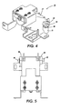
- Figures 4 to 10 show various views and details relating to one specific embodiment of a counter-balance mechanism in accordance with the present invention. It will be appreciated that the invention is not limited to this specific embodiment.
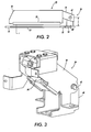
- the mechanism 70 consists of an upper steel member 72 pivotally mounted to a lower steel member 73 about the longitudinal axis of a pivot shaft 76.
- the pivot shaft 76 is more clearly seen in Figures 8 and 9.
- the shaft 76 is fixed relative to the lower member 73 but arranged to be movable relative to the upper member 72.
- the upper member 72 is provided with a pair of opposed slots 78 formed in its sidewalls 80, 82, the ends of the shaft 76 each extending through a respective one of the slots outwardly from the sidewalls.
- Two identical multi-sided cams 84, 86 are provided on each end of the shaft 76, each cam having each of its sides set at differing distances from each respective centre-point.
- the upper member 72 is provided with two extensions, defining feet 88,90, integral with the sidewalls. Each of the cams 84, 86 rests on and is supported by the respective feet 88, 90.
- the shaft 76 is fixed relative to the lower member 73, yet variable relative to the upper member 72, so the height "c" (see Figure 2) of the hinge unit of the counter-balance may be adjusted.
- the number of adjustments is dependent on the number of sides of the cam 84.
- the resolved component of the spring force which results from the captive spring mechanism 64 within the counter-balance, and which acts on the shaft 76 in the direction normal to the plane of the feet 88, 90, prevents the cam from rotating in the usual course of operation of the counter-balance.
- the captive spring mechanism is a compression spring exerting a force of 1400 Newtons at maximum compression when the document handler is in "down" position, ie in contact with the platen, the document handler itself weighing up to 12.4 Kg.
- the force acting on the feet 88, 90 is therefore considerable. It has however been found to be surprisingly easy to rotate the shaft 76 when required by the application of a small spanner to one of the square ends 92, 94 formed on the ends of the shaft 76. It has also been found surprisingly that the cams 84,86 suitable for use can be moulded from plastics material such as, by way of example, 60% glass-filled nylon..
- the centre-hole of the cams 92, 94 is asymmetric. This ensures that in the case when two, or more, cams locate on the shaft 76, the orientation of each cam relative to the shaft 76 must be identical i.e. there could be no possibility of mis-assembly during manufacture.
- a further improvement of the invention over the current counter-balance technology and its use with document handlers for copiers is that in use the adjustments (set / reset) in the present invention are both faster to make and more straightforward . This in turn leads to substantial savings in maintenance time and therefore substantial savings in maintenance costs associated with copier servicing.
- the use of the cams also provides a precision in the adjustment of the height of the document handler which is difficult to achieve in the prior art .
Landscapes
- Physics & Mathematics (AREA)
- General Physics & Mathematics (AREA)
- Exposure Or Original Feeding In Electrophotography (AREA)
- Sheets, Magazines, And Separation Thereof (AREA)
- Electrophotography Configuration And Component (AREA)
- Conveyance By Endless Belt Conveyors (AREA)
- Holders For Sensitive Materials And Originals (AREA)
Applications Claiming Priority (2)
| Application Number | Priority Date | Filing Date | Title |
|---|---|---|---|
| GB9522257 | 1995-10-31 | ||
| GBGB9522257.6A GB9522257D0 (en) | 1995-10-31 | 1995-10-31 | Counter-balance mechanism |
Publications (2)
| Publication Number | Publication Date |
|---|---|
| EP0772096A1 true EP0772096A1 (fr) | 1997-05-07 |
| EP0772096B1 EP0772096B1 (fr) | 2001-12-05 |
Family
ID=10783151
Family Applications (1)
| Application Number | Title | Priority Date | Filing Date |
|---|---|---|---|
| EP96306958A Expired - Lifetime EP0772096B1 (fr) | 1995-10-31 | 1996-09-25 | Mécanisme à contrepoids |
Country Status (6)
| Country | Link |
|---|---|
| US (1) | US5748293A (fr) |
| EP (1) | EP0772096B1 (fr) |
| JP (1) | JPH09185190A (fr) |
| BR (1) | BR9605358A (fr) |
| DE (1) | DE69617607T2 (fr) |
| GB (1) | GB9522257D0 (fr) |
Families Citing this family (4)
| Publication number | Priority date | Publication date | Assignee | Title |
|---|---|---|---|---|
| JP3641357B2 (ja) * | 1997-09-24 | 2005-04-20 | 加藤電機株式会社 | 原稿圧着板開閉装置 |
| US8477327B2 (en) | 2005-11-02 | 2013-07-02 | Xerox Corporation | Scanner registration systems and methods for providing a notification of a scanner re-registration requirement when statistics are outside predetermined registration range |
| US7755808B2 (en) * | 2005-11-17 | 2010-07-13 | Xerox Corporation | Document scanner dust detection systems and methods |
| US8675262B2 (en) * | 2010-03-25 | 2014-03-18 | Kyocera Document Solutions Inc. | Image reading device and image forming apparatus including the same |
Citations (4)
| Publication number | Priority date | Publication date | Assignee | Title |
|---|---|---|---|---|
| JPS5770526A (en) * | 1980-10-18 | 1982-05-01 | Nhk Spring Co Ltd | Opening and closing device for original pressure plate of copying machine |
| US4520977A (en) * | 1982-09-29 | 1985-06-04 | Eastman Kodak Company | Apparatus for mounting a document feeder on a copier/duplicator |
| US4853750A (en) * | 1987-02-26 | 1989-08-01 | Sharp Kabushiki Kaisha | Document holder for a copier and hinge mechanism therefor |
| EP0573022A2 (fr) * | 1992-06-02 | 1993-12-08 | Mita Industrial Co. Ltd. | Appareil d'avancement de documents automatique |
Family Cites Families (4)
| Publication number | Priority date | Publication date | Assignee | Title |
|---|---|---|---|---|
| US4185908A (en) * | 1977-06-30 | 1980-01-29 | Xerox Corporation | Vernier belt tensioning system for a photocopying machine |
| US4114236A (en) * | 1977-07-28 | 1978-09-19 | Minnesota Mining & Manufacturing Company | Hinge structure for platen covers |
| US5104244A (en) * | 1991-03-01 | 1992-04-14 | International Business Machines Corp. | Printer throat control mechanism |
| GB9400845D0 (en) * | 1994-01-18 | 1994-03-16 | Xerox Corp | Document handler |
-
1995
- 1995-10-31 GB GBGB9522257.6A patent/GB9522257D0/en active Pending
-
1996
- 1996-09-25 EP EP96306958A patent/EP0772096B1/fr not_active Expired - Lifetime
- 1996-09-25 DE DE69617607T patent/DE69617607T2/de not_active Expired - Fee Related
- 1996-10-28 US US08/738,746 patent/US5748293A/en not_active Expired - Lifetime
- 1996-10-30 BR BR9605358A patent/BR9605358A/pt not_active Application Discontinuation
- 1996-10-31 JP JP8289469A patent/JPH09185190A/ja not_active Withdrawn
Patent Citations (4)
| Publication number | Priority date | Publication date | Assignee | Title |
|---|---|---|---|---|
| JPS5770526A (en) * | 1980-10-18 | 1982-05-01 | Nhk Spring Co Ltd | Opening and closing device for original pressure plate of copying machine |
| US4520977A (en) * | 1982-09-29 | 1985-06-04 | Eastman Kodak Company | Apparatus for mounting a document feeder on a copier/duplicator |
| US4853750A (en) * | 1987-02-26 | 1989-08-01 | Sharp Kabushiki Kaisha | Document holder for a copier and hinge mechanism therefor |
| EP0573022A2 (fr) * | 1992-06-02 | 1993-12-08 | Mita Industrial Co. Ltd. | Appareil d'avancement de documents automatique |
Non-Patent Citations (1)
| Title |
|---|
| PATENT ABSTRACTS OF JAPAN vol. 006, no. 152 (P - 134) 12 August 1982 (1982-08-12) * |
Also Published As
| Publication number | Publication date |
|---|---|
| BR9605358A (pt) | 1998-07-28 |
| US5748293A (en) | 1998-05-05 |
| GB9522257D0 (en) | 1996-01-03 |
| EP0772096B1 (fr) | 2001-12-05 |
| DE69617607D1 (de) | 2002-01-17 |
| DE69617607T2 (de) | 2002-05-08 |
| JPH09185190A (ja) | 1997-07-15 |
Similar Documents
| Publication | Publication Date | Title |
|---|---|---|
| EP0523707B1 (fr) | Trieuse | |
| US11313807B2 (en) | Image inspection device | |
| EP0352813A2 (fr) | Dispositif d'alimentation de feuilles pour machine de reproduction et de traitement | |
| US6315284B1 (en) | Sheet feeding apparatus and sheet processing apparatus | |
| US11312588B2 (en) | Automatic document feeders | |
| US4853750A (en) | Document holder for a copier and hinge mechanism therefor | |
| CA1082633A (fr) | Systeme a vernier pour regler la tension des courroies | |
| EP3617808A2 (fr) | Dispositif de transport et dispositif d'inspection d'image | |
| EP0772096B1 (fr) | Mécanisme à contrepoids | |
| EP0983950B1 (fr) | Chargeur automatique de produits pour un margeur de feuilles | |
| US5618034A (en) | Supply/conveyance mechanism for sheets of paper | |
| JP3249721B2 (ja) | シート材給送装置及び画像形成装置 | |
| CA2370831C (fr) | Controleur de niveau de pile de feuilles et methode d'utilisation de ce dernier | |
| JP2716225B2 (ja) | シート堆積装置 | |
| US5222730A (en) | Sheeet conveyor joint mechanism | |
| US4564189A (en) | Articulating sheet material conveyor | |
| USRE43682E1 (en) | Pressure-adjustable mechanism for paper feeding roller of automatic paper feeder | |
| US7735825B2 (en) | Original feeding device | |
| JP2000191215A (ja) | シート積載装置 | |
| US5010364A (en) | Copier with automatic document feed having jam prevention function | |
| JPH09150990A (ja) | 給紙装置 | |
| CA1303632C (fr) | Dispositif d'alimentation automatique en documents pour imprimante | |
| EP1009700B1 (fr) | Distributeur de feuilles une par une et analyseur equipe d'un tel distributeur | |
| JPH1072134A (ja) | シート搬送装置 | |
| JPH03171160A (ja) | 画像形成装置 |
Legal Events
| Date | Code | Title | Description |
|---|---|---|---|
| PUAI | Public reference made under article 153(3) epc to a published international application that has entered the european phase |
Free format text: ORIGINAL CODE: 0009012 |
|
| AK | Designated contracting states |
Kind code of ref document: A1 Designated state(s): DE FR GB |
|
| 17P | Request for examination filed |
Effective date: 19971107 |
|
| GRAG | Despatch of communication of intention to grant |
Free format text: ORIGINAL CODE: EPIDOS AGRA |
|
| 17Q | First examination report despatched |
Effective date: 20001130 |
|
| GRAG | Despatch of communication of intention to grant |
Free format text: ORIGINAL CODE: EPIDOS AGRA |
|
| GRAH | Despatch of communication of intention to grant a patent |
Free format text: ORIGINAL CODE: EPIDOS IGRA |
|
| GRAH | Despatch of communication of intention to grant a patent |
Free format text: ORIGINAL CODE: EPIDOS IGRA |
|
| GRAH | Despatch of communication of intention to grant a patent |
Free format text: ORIGINAL CODE: EPIDOS IGRA |
|
| GRAA | (expected) grant |
Free format text: ORIGINAL CODE: 0009210 |
|
| AK | Designated contracting states |
Kind code of ref document: B1 Designated state(s): DE FR GB |
|
| REG | Reference to a national code |
Ref country code: GB Ref legal event code: IF02 |
|
| REF | Corresponds to: |
Ref document number: 69617607 Country of ref document: DE Date of ref document: 20020117 |
|
| ET | Fr: translation filed | ||
| PLBE | No opposition filed within time limit |
Free format text: ORIGINAL CODE: 0009261 |
|
| STAA | Information on the status of an ep patent application or granted ep patent |
Free format text: STATUS: NO OPPOSITION FILED WITHIN TIME LIMIT |
|
| 26N | No opposition filed | ||
| PGFP | Annual fee paid to national office [announced via postgrant information from national office to epo] |
Ref country code: FR Payment date: 20040908 Year of fee payment: 9 |
|
| PGFP | Annual fee paid to national office [announced via postgrant information from national office to epo] |
Ref country code: GB Payment date: 20040922 Year of fee payment: 9 |
|
| PGFP | Annual fee paid to national office [announced via postgrant information from national office to epo] |
Ref country code: DE Payment date: 20040923 Year of fee payment: 9 |
|
| PG25 | Lapsed in a contracting state [announced via postgrant information from national office to epo] |
Ref country code: GB Free format text: LAPSE BECAUSE OF NON-PAYMENT OF DUE FEES Effective date: 20050925 |
|
| PG25 | Lapsed in a contracting state [announced via postgrant information from national office to epo] |
Ref country code: DE Free format text: LAPSE BECAUSE OF NON-PAYMENT OF DUE FEES Effective date: 20060401 |
|
| GBPC | Gb: european patent ceased through non-payment of renewal fee |
Effective date: 20050925 |
|
| PG25 | Lapsed in a contracting state [announced via postgrant information from national office to epo] |
Ref country code: FR Free format text: LAPSE BECAUSE OF NON-PAYMENT OF DUE FEES Effective date: 20060531 |
|
| REG | Reference to a national code |
Ref country code: FR Ref legal event code: ST Effective date: 20060531 |