EP0772100A2 - Rouleau de fixage par fusion utilisant un fluide à changement de phase - Google Patents
Rouleau de fixage par fusion utilisant un fluide à changement de phase Download PDFInfo
- Publication number
- EP0772100A2 EP0772100A2 EP19960307856 EP96307856A EP0772100A2 EP 0772100 A2 EP0772100 A2 EP 0772100A2 EP 19960307856 EP19960307856 EP 19960307856 EP 96307856 A EP96307856 A EP 96307856A EP 0772100 A2 EP0772100 A2 EP 0772100A2
- Authority
- EP
- European Patent Office
- Prior art keywords
- fusing
- fusing member
- fluid
- sheet
- heat
- Prior art date
- Legal status (The legal status is an assumption and is not a legal conclusion. Google has not performed a legal analysis and makes no representation as to the accuracy of the status listed.)
- Withdrawn
Links
- 239000012530 fluid Substances 0.000 title claims abstract description 24
- 230000008859 change Effects 0.000 title description 7
- 239000000126 substance Substances 0.000 claims abstract description 8
- 239000000203 mixture Substances 0.000 claims abstract description 4
- 238000010438 heat treatment Methods 0.000 claims description 11
- 239000000758 substrate Substances 0.000 claims description 9
- DNIAPMSPPWPWGF-UHFFFAOYSA-N Propylene glycol Chemical compound CC(O)CO DNIAPMSPPWPWGF-UHFFFAOYSA-N 0.000 claims description 6
- 238000000034 method Methods 0.000 claims description 6
- XLYOFNOQVPJJNP-UHFFFAOYSA-N water Substances O XLYOFNOQVPJJNP-UHFFFAOYSA-N 0.000 claims description 5
- 238000012546 transfer Methods 0.000 abstract description 24
- 239000007788 liquid Substances 0.000 abstract description 13
- 238000013021 overheating Methods 0.000 abstract description 3
- 239000002245 particle Substances 0.000 description 10
- 239000000843 powder Substances 0.000 description 9
- 229920002799 BoPET Polymers 0.000 description 8
- 239000005041 Mylar™ Substances 0.000 description 8
- 230000032258 transport Effects 0.000 description 8
- 238000009833 condensation Methods 0.000 description 5
- 230000005494 condensation Effects 0.000 description 5
- 239000000463 material Substances 0.000 description 5
- 238000004140 cleaning Methods 0.000 description 4
- 238000009826 distribution Methods 0.000 description 4
- 239000008187 granular material Substances 0.000 description 3
- 230000001133 acceleration Effects 0.000 description 2
- 238000009835 boiling Methods 0.000 description 2
- 238000001704 evaporation Methods 0.000 description 2
- 230000008020 evaporation Effects 0.000 description 2
- 239000000835 fiber Substances 0.000 description 2
- 108091008695 photoreceptors Proteins 0.000 description 2
- 230000008569 process Effects 0.000 description 2
- 229920006395 saturated elastomer Polymers 0.000 description 2
- 238000007493 shaping process Methods 0.000 description 2
- RYGMFSIKBFXOCR-UHFFFAOYSA-N Copper Chemical compound [Cu] RYGMFSIKBFXOCR-UHFFFAOYSA-N 0.000 description 1
- 238000006424 Flood reaction Methods 0.000 description 1
- 230000015572 biosynthetic process Effects 0.000 description 1
- 229910052802 copper Inorganic materials 0.000 description 1
- 239000010949 copper Substances 0.000 description 1
- 238000012937 correction Methods 0.000 description 1
- 230000001934 delay Effects 0.000 description 1
- 238000011161 development Methods 0.000 description 1
- 239000006185 dispersion Substances 0.000 description 1
- 229920001971 elastomer Polymers 0.000 description 1
- 239000000284 extract Substances 0.000 description 1
- 230000004907 flux Effects 0.000 description 1
- 238000005286 illumination Methods 0.000 description 1
- 238000003384 imaging method Methods 0.000 description 1
- 230000006872 improvement Effects 0.000 description 1
- 150000002500 ions Chemical class 0.000 description 1
- 230000007246 mechanism Effects 0.000 description 1
- 238000012545 processing Methods 0.000 description 1
- 230000001105 regulatory effect Effects 0.000 description 1
- 238000004088 simulation Methods 0.000 description 1
- 239000007921 spray Substances 0.000 description 1
- 238000009834 vaporization Methods 0.000 description 1
- 230000008016 vaporization Effects 0.000 description 1
Images




Classifications
-
- G—PHYSICS
- G03—PHOTOGRAPHY; CINEMATOGRAPHY; ANALOGOUS TECHNIQUES USING WAVES OTHER THAN OPTICAL WAVES; ELECTROGRAPHY; HOLOGRAPHY
- G03G—ELECTROGRAPHY; ELECTROPHOTOGRAPHY; MAGNETOGRAPHY
- G03G15/00—Apparatus for electrographic processes using a charge pattern
- G03G15/20—Apparatus for electrographic processes using a charge pattern for fixing, e.g. by using heat
- G03G15/2003—Apparatus for electrographic processes using a charge pattern for fixing, e.g. by using heat using heat
- G03G15/2014—Apparatus for electrographic processes using a charge pattern for fixing, e.g. by using heat using heat using contact heat
- G03G15/2053—Structural details of heat elements, e.g. structure of roller or belt, eddy current, induction heating
Definitions
- This invention relates generally to a fusing system, and more particularly concerns a fusing member which provides a very uniform fusing temperature along its axis and a high transfer efficiency for fusing images to a sheet.
- a photoconductive member is charged to a substantially uniform potential so as to sensitize the surface thereof.
- the charged portion of the photoconductive member is exposed to a light image of an original document being reproduced. Exposure of the charged photoconductive member selectively dissipates the charges thereon in the irradiated areas. This records an electrostatic latent image on the photoconductive member corresponding to the informational areas contained within the original document.
- the latent image is developed by bringing a developer material into contact therewith.
- the developer material comprises toner particles adhering triboelectrically to carrier granules.
- the toner particles are attracted from the carrier granules to the latent image forming a toner powder image on the photoconductive member.
- the toner powder image is then transferred from the photoconductive member to a copy sheet.
- the toner particles are heated to permanently affix the powder image to the copy sheet.
- Most current fusers use conduction as the main heat transfer mechanism to melt toner to paper. Such systems suffer from non-uniform axial temperature distributions when various paper widths are fed through the fusing nip.
- the object of this invention is to achieve a uniform axial temperature distribution on the surface of the roll, for any paper or film width and/or speed variation. Accordingly, it is desirable to develop a fuser which has good heat transfer properties and is able to be maintained at a uniform axial temperature.
- U.S.-A-5,119,142 describes an image fixing device in which a heat exchanging roller removes heat from a portion of a belt exiting a fusing nip and returns the heat to a portion of the belt entering the nip.
- the heat exchanging roller has a thin conducting layer on an insulative core.
- an apparatus for fusing images to a substrate comprises a pressure member and a heated fusing member, the fusing member heated so that the temperature in an axial direction along the fusing member remains substantially constant.
- an electrophotographic printing machine in which images are fused to a substrate.
- the machine comprises a pressure member and a heated fusing member, the fusing member heated so that the temperature in an axial direction along the fusing member remains substantially constant.
- a method of heating a fusing member in a printing machine comprising maintaining a substantially pure fluid substance or mixture of substantially pur substances in a sealed fusing member, heating said fluid to maintain said fluid in a two phase (liquid and vapor) condition and contacting a sheet with an unfused image thereon with the fusing member so as to fuse an image thereon.
- Fig. 1 schematically depicts an electrophotographic printing machine incorporating the features of the present invention therein. It will become evident from the following discussion that the stalled roll registration device of the present invention may be employed in a wide variety of devices and is not specifically limited in its application to the particular embodiment depicted herein.
- an original document is positioned in a document handler 27 on a raster input scanner (RIS) indicated generally by reference numeral 28.
- the RIS contains document illumination lamps, optics, a mechanical scanning drive and a charge coupled device (CCD) array.
- CCD charge coupled device
- the RIS captures the entire original document and converts it to a series of raster scan lines. This information is transmitted to an electronic subsystem (ESS) which controls a raster output scanner (ROS) described below.
- ESS electronic subsystem
- ROS raster output scanner
- FIG. 1 schematically illustrates an electrophotographic printing machine which generally employs a photoconductive belt 10.
- the photoconductive belt 10 is made from a photoconductive material coated on a ground layer, which, in turn, is coated on an anti-curl backing layer.
- Belt 10 moves in the direction of arrow 13 to advance successive portions sequentially through the various processing stations disposed about the path of movement thereof.
- Belt 10 is entrained about stripping roller 14, tensioning roller 16 and drive roller 20. As roller 20 rotates, it advances belt 10 in the direction of arrow 13. Initially, a portion of the photoconductive surface passes through charging station A.
- a corona generating device indicated generally by the reference numeral 22 charges the photoconductive belt 10 to a relatively high, substantially uniform potential.
- ESS 29 receives the image signals representing the desired output image and processes these signals to convert them to a continuous tone or greyscale rendition of the image which is transmitted to a modulated output generator, for example the raster output scanner (ROS), indicated generally by reference numeral 30.
- ESS 29 is a self-contained, dedicated minicomputer.
- the image signals transmitted to ESS 29 may originate from a RIS as described above or from a computer, thereby enabling the electrophotographic printing machine to serve as a remotely located printer for one or more computers.
- the printer may serve as a dedicated printer for a high-speed computer.
- ROS 30 includes a laser with rotating polygon mirror blocks. Preferably, a nine facet polygon is used.
- the ROS illuminates the charged portion of photoconductive belt 10 at a resolution of about 300 or more pixels per inch.
- the ROS will expose the photoconductive belt to record an electrostatic latent image thereon corresponding to the continuous tone image received from ESS 29.
- ROS 30 may employ a linear array of light emitting diodes (LEDs) arranged to illuminate the charged portion of photoconductive belt 10 on a raster-by-raster basis.
- LEDs light emitting diodes
- belt 10 advances the latent image to a development station, C, where toner, in the form of liquid or dry particles, is electrostatically attracted to the latent image using commonly known techniques.
- the latent image attracts toner particles from the carrier granules forming a toner powder image thereon.
- a toner particle dispenser indicated generally by the reference numeral 44, dispenses toner particles into developer housing 46 of developer unit 38.
- sheet feeding apparatus 50 includes a feed roll 52 contacting the uppermost sheet of stack 54. Feed roll 52 rotates to advance the uppermost sheet from stack 54 into vertical transport 56. Vertical transport 56 directs the advancing sheet 48 of support material into registration transport 57 past image transfer station D to receive an image from photoreceptor belt 10 in a timed sequence so that the toner powder image formed thereon contacts the advancing sheet 48 at transfer station D.
- Transfer station D includes a corona generating device 58 which sprays ions onto the back side of sheet 48. This attracts the toner powder image from photoconductive surface 12 to sheet 48. After transfer, sheet 48 continues to move in the direction of arrow 60 by way of belt transport 62 which advances sheet 48 to fusing station F.
- Fusing station F includes a fuser assembly indicated generally by the reference numeral 70 which permanently affixes the transferred toner powder image to the copy sheet.
- fuser assembly 70 includes a heated fuser roller 72 and a pressure roller 74 with the powder image on the copy sheet contacting fuser roller 72.
- the fuser system will be described in more detail with reference to Figures 2-8 inclusive.
- a gate 80 either allows the sheet to move directly via output 16 to a finisher or stacker, or deflects the sheet into the duplex path 100, specifically, first into single sheet inverter 82 here. That is, if the sheet is either a simplex sheet, or a completed duplex sheet having both side one and side two images formed thereon, the sheet will be conveyed via gate 80 directly to output 16.
- the gate 80 will be positioned to deflect that sheet into the inverter 82 and into the duplex loop path 100, where that sheet will be inverted and then fed to acceleration nip 102 and belt transports 110, for recirculation back through transfer station D and fuser 70 for receiving and permanently fixing the side two image to the backside of that duplex sheet, before it exits via exit path 16.
- Cleaning station E includes a rotatably mounted fibrous brush in contact with photoconductive surface 12 to disturb and remove paper fibers and a cleaning blade to remove the nontransferred toner particles.
- the blade may be configured in either a wiper or doctor position depending on the application.
- a discharge lamp (not shown) floods photoconductive surface 12 with light to dissipate any residual electrostatic charge remaining thereon prior to the charging thereof for the next successive imaging cycle.
- the various machine functions are regulated by controller 29.
- the controller is preferably a programmable microprocessor which controls all of the machine functions hereinbefore described.
- the controller provides a comparison count of the copy sheets, the number of documents being recirculated, the number of copy sheets selected by the operator, time delays, jam corrections, etc..
- the control of all of the exemplary systems heretofore described may be accomplished by conventional control switch inputs from the printing machine consoles selected by the operator.
- Conventional sheet path sensors or switches may be utilized to keep track of the position of the document and the copy sheets.
- FIGs 2 and 3 illustrate a cross sectional view of two embodiments of the fuser herein.
- the fuser roll is a sealed cylindrical member or chamber containing a pure working fluid.
- a heat source (174), either external to the roll (Fig. 2) or internal to the roll (Fig. 3) is used to heat the working fluid.
- the pressure in the chamber must equal the corresponding saturation pressure.
- the chamber substantially evacuated of air and any other non-condensible substance, is partially filled with the working fluid and then sealed. Heat is provided (either internally or externally) to raise the temperature to the desired level. At steady state the amount of heat added must equal that which is lost to the ambient. Heat transfer occurs primarily through evaporation of the liquid and condensation of the vapor.
- the table below lists the saturation temperatures and pressures for pure water. Temperature, °C Pressure, psia 20 0.4 100.6 15 108.9 20 115.6 25 121.3 30 130.7 40
- the chamber would have to be evacuated to a pressure of 0.4 psia at ambient temperature (20 °C).
- the pressure increases to 40 psia when the temperature reaches 130.7 °C.
- the system must be designed to withstand both extremes to avoid leakage into or out of the chamber.
- the substrate can be copy paper, a photoreceptor or intermediate transfer belt, or a web fed film.
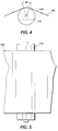
- Fusers need to accommodate various substrate widths and thermal characteristics. Utilizing the system described herein, axial temperature variations will essentially be removed. In the case of a fuser for a electrophotographic printing machine, however, water is not a viable working fluid because for typical fusing temperatures (190 °C) the saturation pressure is an unwieldy 150 psia. Propylene glycol which has a boiling point of 187.2 °C at atmospheric pressure is a good candidate. Selective transfer of energy is best achieved with a roll as thin as is structurally viable, having a high thermal conductivity (e.g. copper). An example is shown in Figures 3 and 4.
- the roll is made of copper 0.25 cm thick with an outer diameter of 8 cm.
- the wrap angle is 36° so that contact occurs over a length of 2.51 cm.
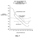
- the mylar film enters the wrap at 20 °C. Its axial surface temperature distribution upon leaving the wrap, was determined by use of a three dimensional heat transfer simulation program. Heat transfer by vapor condensation was represented by an average heat transfer coefficient obtained from, where:
- Tsv temperature of saturated vapor
- Fig. 6 The results with a conventional fuser of the exact same geometry and with identical operating conditions, are shown in Fig. 6. For comparison, the results of Fig. 6 are also included. Heating with a conventional fuser produces significant surface temperature variations because of the non-uniform output of the heating lamp. In this example a 2 kW lamp with the profile shown in Fig. 8 is assumed. In spite of a diffusely reflecting, low emissivity (0.1) cavity the surface heating distribution retains significant axial variation, as shown in Fig. 8. The marked improvement of the phase change fuser evident in Fig., is due to the dispersion and relatively unimpeded flow of vapor which effectively eliminates any variations of the heat source.
- the temperature on the rolls outside the paper path usually rises to much higher values than desired unless some shaping of the lamp profile or multiple lamps are used.
- the phase change fuser will remove heat from the hot areas outside the paper path by evaporation and transport this heat to areas within the paper width where condensation will occur, thus maintaining uniform axial temperatures. without use of shaped heating or multiple heating devices.
- an apparatus for fusing images to a sheet A fuser device is provided using a sealed fusing member containing a pure fluid substance. Heat is applied, either internally or externally, to maintain the fluid in a steady state condition. When a sheet having an unfused image thereon is fed between the fusing member and a pressure member, the heat is transferred to the sheet to fuse the image. As a result of the two phase (liquid and vapor) state of the fluid within the fusing member there is a very uniform and efficient transfer of heat to the sheet.
- a device which maintains a very uniform temperature along its axis and avoids hot spots and overheating of certain portions of the fusing member due to variations in the heat source and in the transfer efficiency of the fusing member.
Landscapes
- Physics & Mathematics (AREA)
- General Physics & Mathematics (AREA)
- Fixing For Electrophotography (AREA)
Applications Claiming Priority (2)
| Application Number | Priority Date | Filing Date | Title |
|---|---|---|---|
| US55069695A | 1995-10-31 | 1995-10-31 | |
| US550696 | 1995-10-31 |
Publications (1)
| Publication Number | Publication Date |
|---|---|
| EP0772100A2 true EP0772100A2 (fr) | 1997-05-07 |
Family
ID=24198240
Family Applications (1)
| Application Number | Title | Priority Date | Filing Date |
|---|---|---|---|
| EP19960307856 Withdrawn EP0772100A2 (fr) | 1995-10-31 | 1996-10-30 | Rouleau de fixage par fusion utilisant un fluide à changement de phase |
Country Status (3)
| Country | Link |
|---|---|
| EP (1) | EP0772100A2 (fr) |
| JP (1) | JPH09166931A (fr) |
| BR (1) | BR9605225A (fr) |
Cited By (9)
| Publication number | Priority date | Publication date | Assignee | Title |
|---|---|---|---|---|
| WO2000031593A1 (fr) * | 1998-11-25 | 2000-06-02 | Indigo N.V. | Fixeur et tambour de transfert intermediaire |
| WO2002031601A1 (fr) * | 2000-10-13 | 2002-04-18 | Hewlett-Packard Indigo B.V. | Unite de fusion et tambours de transfert intermediaire |
| EP1220054A1 (fr) * | 2000-12-22 | 2002-07-03 | Samsung Electronics Co., Ltd. | Ensemble de fixage avec un fluide de travail dans le rouleau chauffant d'un appareil électrophotographique de formation d'images |
| US6571080B2 (en) | 2000-12-22 | 2003-05-27 | Samsung Electronics Co., Ltd. | Fusing roller assembly having working fluid and heater coil for quick heating and low power consumption for an electrophotographic image forming apparatus and method of making the same |
| WO2003044604A1 (fr) * | 2001-11-06 | 2003-05-30 | Hewlett-Packard Indigo B.V. | Appareils de fusion et elements de transfert intermediaire |
| WO2003046667A1 (fr) * | 2001-10-30 | 2003-06-05 | Hewlett-Packard Indigo B.V. | Fixeurs et elements de transfert intermediaires |
| US6580896B2 (en) | 2000-12-22 | 2003-06-17 | Samsung Electronics Co., Ltd. | Fusing roller assembly for electrophotographic image forming apparatus |
| US8849170B2 (en) * | 2012-10-29 | 2014-09-30 | Eastman Kodak Company | Toner fixer with liquid-carrying porous material |
| CN104614963A (zh) * | 2013-11-01 | 2015-05-13 | 东友科技股份有限公司 | 滚轮及其适用的定影装置 |
Families Citing this family (1)
| Publication number | Priority date | Publication date | Assignee | Title |
|---|---|---|---|---|
| KR100503065B1 (ko) * | 2002-08-29 | 2005-07-21 | 삼성전자주식회사 | 전자사진 화상형성장치의 정착 장치 |
Citations (1)
| Publication number | Priority date | Publication date | Assignee | Title |
|---|---|---|---|---|
| US5119142A (en) | 1991-09-03 | 1992-06-02 | Eastman Kodak Company | Image fixing device having heat recycling means |
-
1996
- 1996-10-23 BR BR9605225A patent/BR9605225A/pt not_active Application Discontinuation
- 1996-10-24 JP JP28117696A patent/JPH09166931A/ja not_active Withdrawn
- 1996-10-30 EP EP19960307856 patent/EP0772100A2/fr not_active Withdrawn
Patent Citations (1)
| Publication number | Priority date | Publication date | Assignee | Title |
|---|---|---|---|---|
| US5119142A (en) | 1991-09-03 | 1992-06-02 | Eastman Kodak Company | Image fixing device having heat recycling means |
Cited By (13)
| Publication number | Priority date | Publication date | Assignee | Title |
|---|---|---|---|---|
| WO2000031593A1 (fr) * | 1998-11-25 | 2000-06-02 | Indigo N.V. | Fixeur et tambour de transfert intermediaire |
| US6584294B1 (en) | 1998-11-25 | 2003-06-24 | Hewlett-Packard Indigo B.V. | Fuser and intermediate transfer drums |
| WO2002031601A1 (fr) * | 2000-10-13 | 2002-04-18 | Hewlett-Packard Indigo B.V. | Unite de fusion et tambours de transfert intermediaire |
| US7092667B1 (en) | 2000-10-13 | 2006-08-15 | Hewlett-Packard Development Company, L.P. | Fuser and intermediate transfer drums |
| EP1378803A3 (fr) * | 2000-10-13 | 2004-01-14 | Hewlett-Packard Indigo B.V. | Elément de fixage et tambours de transfert intermédiare |
| US6580896B2 (en) | 2000-12-22 | 2003-06-17 | Samsung Electronics Co., Ltd. | Fusing roller assembly for electrophotographic image forming apparatus |
| US6571080B2 (en) | 2000-12-22 | 2003-05-27 | Samsung Electronics Co., Ltd. | Fusing roller assembly having working fluid and heater coil for quick heating and low power consumption for an electrophotographic image forming apparatus and method of making the same |
| US6792239B2 (en) | 2000-12-22 | 2004-09-14 | Samsung Electronics Co., Ltd | Fusing roller assembly for electrophotographic image forming apparatus |
| EP1220054A1 (fr) * | 2000-12-22 | 2002-07-03 | Samsung Electronics Co., Ltd. | Ensemble de fixage avec un fluide de travail dans le rouleau chauffant d'un appareil électrophotographique de formation d'images |
| WO2003046667A1 (fr) * | 2001-10-30 | 2003-06-05 | Hewlett-Packard Indigo B.V. | Fixeurs et elements de transfert intermediaires |
| WO2003044604A1 (fr) * | 2001-11-06 | 2003-05-30 | Hewlett-Packard Indigo B.V. | Appareils de fusion et elements de transfert intermediaire |
| US8849170B2 (en) * | 2012-10-29 | 2014-09-30 | Eastman Kodak Company | Toner fixer with liquid-carrying porous material |
| CN104614963A (zh) * | 2013-11-01 | 2015-05-13 | 东友科技股份有限公司 | 滚轮及其适用的定影装置 |
Also Published As
| Publication number | Publication date |
|---|---|
| JPH09166931A (ja) | 1997-06-24 |
| BR9605225A (pt) | 1998-07-21 |
Similar Documents
| Publication | Publication Date | Title |
|---|---|---|
| US4708460A (en) | Simultaneous transfer and fusing in electrophotography | |
| US3449548A (en) | Fusing device | |
| US5602635A (en) | Rapid wake up fuser | |
| US5887235A (en) | Variable gloss fuser | |
| EP0244198B1 (fr) | Fixage à chaleur pour images avec développement liquide | |
| US20070237536A1 (en) | High precision-heating and fusing apparatus | |
| US5689788A (en) | Heat and pressure roll fuser with substantially uniform velocity | |
| US5784679A (en) | Apparatus for drying and pressing an image to a copy sheet | |
| EP0772100A2 (fr) | Rouleau de fixage par fusion utilisant un fluide à changement de phase | |
| US5689789A (en) | Uniform nip velocity roll fuser | |
| US4008955A (en) | Fuser assembly for an electrophotograhic copying machine | |
| US3924564A (en) | Fusing apparatus having an articulated release material dispenser | |
| US5689767A (en) | Isothermalizing member for a printing machine | |
| EP0097034B1 (fr) | Fuseur par pression | |
| US5410394A (en) | Three roller design eliminates free span belt heating of integral heating fusing belt | |
| US5585909A (en) | Flame sprayed ceramic end caps | |
| US6909871B2 (en) | Method and device for fusing toner onto a substrate | |
| CA1059170A (fr) | Appareil pour retirer les feuilles d'un rouleau de cuisson | |
| CA1058273A (fr) | Fusionneur radiant pour appareil de reproduction xerographique | |
| US4000394A (en) | Fuser thermal detector | |
| US4903082A (en) | Liquid ink fusing and drying system | |
| US5634184A (en) | Single roll RAM system w/rotating wick | |
| EP0532235B1 (fr) | Rouleau donneur préchauffé pour la distribution d'huile, pressé par un ressort | |
| EP0929013B1 (fr) | Guide anti-gondolement en avant d'une unité de fixage par fusion | |
| US20080138102A1 (en) | Rapid warm-up and cool-down pressure roll assembly and a fusing apparatus including same |
Legal Events
| Date | Code | Title | Description |
|---|---|---|---|
| PUAI | Public reference made under article 153(3) epc to a published international application that has entered the european phase |
Free format text: ORIGINAL CODE: 0009012 |
|
| AK | Designated contracting states |
Kind code of ref document: A2 Designated state(s): DE FR GB |
|
| RIN1 | Information on inventor provided before grant (corrected) |
Inventor name: PANIDES, ELIAS Inventor name: DOMOTO, GERALD A. |
|
| STAA | Information on the status of an ep patent application or granted ep patent |
Free format text: STATUS: THE APPLICATION HAS BEEN WITHDRAWN |
|
| 18W | Application withdrawn |
Withdrawal date: 19970922 |