EP0772251A1 - Cellule galvanique avec des collecteurs de courant d'électrodes sous forme de fils - Google Patents
Cellule galvanique avec des collecteurs de courant d'électrodes sous forme de fils Download PDFInfo
- Publication number
- EP0772251A1 EP0772251A1 EP96115126A EP96115126A EP0772251A1 EP 0772251 A1 EP0772251 A1 EP 0772251A1 EP 96115126 A EP96115126 A EP 96115126A EP 96115126 A EP96115126 A EP 96115126A EP 0772251 A1 EP0772251 A1 EP 0772251A1
- Authority
- EP
- European Patent Office
- Prior art keywords
- pole
- electrode plates
- cell
- shaped
- bolts
- Prior art date
- Legal status (The legal status is an assumption and is not a legal conclusion. Google has not performed a legal analysis and makes no representation as to the accuracy of the status listed.)
- Granted
Links
Images


Classifications
-
- H—ELECTRICITY
- H01—ELECTRIC ELEMENTS
- H01M—PROCESSES OR MEANS, e.g. BATTERIES, FOR THE DIRECT CONVERSION OF CHEMICAL ENERGY INTO ELECTRICAL ENERGY
- H01M50/00—Constructional details or processes of manufacture of the non-active parts of electrochemical cells other than fuel cells, e.g. hybrid cells
- H01M50/50—Current conducting connections for cells or batteries
- H01M50/528—Fixed electrical connections, i.e. not intended for disconnection
- H01M50/529—Intercell connections through partitions, e.g. in a battery casing
-
- H—ELECTRICITY
- H01—ELECTRIC ELEMENTS
- H01M—PROCESSES OR MEANS, e.g. BATTERIES, FOR THE DIRECT CONVERSION OF CHEMICAL ENERGY INTO ELECTRICAL ENERGY
- H01M50/00—Constructional details or processes of manufacture of the non-active parts of electrochemical cells other than fuel cells, e.g. hybrid cells
- H01M50/10—Primary casings; Jackets or wrappings
- H01M50/172—Arrangements of electric connectors penetrating the casing
- H01M50/174—Arrangements of electric connectors penetrating the casing adapted for the shape of the cells
- H01M50/176—Arrangements of electric connectors penetrating the casing adapted for the shape of the cells for prismatic or rectangular cells
-
- H—ELECTRICITY
- H01—ELECTRIC ELEMENTS
- H01M—PROCESSES OR MEANS, e.g. BATTERIES, FOR THE DIRECT CONVERSION OF CHEMICAL ENERGY INTO ELECTRICAL ENERGY
- H01M50/00—Constructional details or processes of manufacture of the non-active parts of electrochemical cells other than fuel cells, e.g. hybrid cells
- H01M50/50—Current conducting connections for cells or batteries
- H01M50/543—Terminals
- H01M50/552—Terminals characterised by their shape
- H01M50/553—Terminals adapted for prismatic, pouch or rectangular cells
-
- H—ELECTRICITY
- H01—ELECTRIC ELEMENTS
- H01M—PROCESSES OR MEANS, e.g. BATTERIES, FOR THE DIRECT CONVERSION OF CHEMICAL ENERGY INTO ELECTRICAL ENERGY
- H01M50/00—Constructional details or processes of manufacture of the non-active parts of electrochemical cells other than fuel cells, e.g. hybrid cells
- H01M50/50—Current conducting connections for cells or batteries
- H01M50/543—Terminals
- H01M50/564—Terminals characterised by their manufacturing process
- H01M50/567—Terminals characterised by their manufacturing process by fixing means, e.g. screws, rivets or bolts
-
- Y—GENERAL TAGGING OF NEW TECHNOLOGICAL DEVELOPMENTS; GENERAL TAGGING OF CROSS-SECTIONAL TECHNOLOGIES SPANNING OVER SEVERAL SECTIONS OF THE IPC; TECHNICAL SUBJECTS COVERED BY FORMER USPC CROSS-REFERENCE ART COLLECTIONS [XRACs] AND DIGESTS
- Y02—TECHNOLOGIES OR APPLICATIONS FOR MITIGATION OR ADAPTATION AGAINST CLIMATE CHANGE
- Y02E—REDUCTION OF GREENHOUSE GAS [GHG] EMISSIONS, RELATED TO ENERGY GENERATION, TRANSMISSION OR DISTRIBUTION
- Y02E60/00—Enabling technologies; Technologies with a potential or indirect contribution to GHG emissions mitigation
- Y02E60/10—Energy storage using batteries
Definitions
- the invention relates to a galvanic cell which has a prismatic electrode plate set, in which the positive and negative electrode plates are separated by separators and connected to the corresponding pole bolts via current conductors.
- Cells of the aforementioned type are known from document DE-A 2220557.
- the current conductors of the positive or negative electrode plates are then attached to a rod connected to the respective pole bolt using specially shaped clamping pieces.
- galvanic cells are known from document DE-A 2906853, in which two electrode plates of one polarity are connected by a common current conductor and which are thereby fastened in pairs to the corresponding pole bolt by screwing, renting or welding.
- the common current conductor is produced either by welding a metal strip to the edges of two electrode plates or by cutting out the mass-free area of a metal strip serving as an electrode plate carrier.
- Document FR-A 2651606 discloses a pole bolt for an alkaline battery.
- the strip-shaped current conductors of the electrode plates are brought from two sides to the part of the pole bolt located in the cell and connected to it by spot welding.
- the pole bolt has a square shoulder which is in a form-fitting connection with a correspondingly shaped area on the inside of the cell cover.
- the invention has for its object to provide a connection of the electrode plate sets with the pole bolts, which allows automated production of galvanic cells of the type mentioned.
- the galvanic cells according to the invention are characterized in that the current conductors of the electrode plates are wire-shaped and are connected to a sleeve-shaped part of the pole bolts by a press connection.
- the wire-shaped current arresters allow simple mechanical assembly and connection with the inexpensive, sleeve-shaped receiving parts of the pole bolts. Also decrease the wire-shaped current conductors introduce bending moments into the electrode plates and, in cooperation with the sleeve shape of the pole bolt receiving part, permit a press connection leading to cold welding. This crimp connection, which is also known from other areas of electrical engineering, leads to electrical connections which have a low electrical contact resistance.
- the fastening of the current conductors to the electrode plates is advantageously achieved in that the wire-shaped current conductors are flattened in the area of the connection to the electrode plates and are connected by spot, ultrasound or butt welding.
- the connection of the current arrester to the electrode plates according to the invention is simple, can be automated and, in the case of foam, sintered or felt electrodes, allows a high degree of utilization of the available electrode area.
- the pole bolts used in the cells according to the invention are further characterized in that the pole bolts are provided with a sleeve-shaped receiving part in the part of the pole bolt located outside the cell.
- This design of the part of the pole bolts located outside the cell allows an electrically safe and automatable connection to other cells without having to put up with a torque load on the pole bolts.
- pole pin is used as a connector in the intermediate wall of a block box containing a plurality of cells, on one side receiving the current conductors of the positive electrode plates and on the other side those of the negative electrode plates.
- the sleeve-shaped part of the pole bolt is pressed into a defined geometric shape after the current arrester has been received.
- the cell according to the invention is further characterized in that a non-conductive twist protection of the pole bolts is arranged below the cell cover, which is in a positive connection with the geometric shape of the pole bolts obtained by the pressing.
- the galvanic cells according to the invention are advantageously produced by alternately stacking the positive and negative electrode plates, which are already provided with current arresters, in such a way that the current conductors of the respective plate types all lie on one side, a separator being inserted between the individual electrode plates , the current arresters of each polarity are bundled to a uniform length brought and after insertion into the sleeve-shaped part of the pole bolt with this be electrically connected by a press connection.
- the proposed procedure in cooperation with the design of the current arrester and the pole bolts, enables automated production of the galvanic cells.
- the cells are assembled in such a way that the cell cover is pushed onto the pole bolts, the pole bolts are secured by the form-fitting anti-twist protection and are fastened to the cell cover by a nut.
- the pole bolts are attached to the cell cover in that a collar ring is fastened by a rivet-like widening of a pole bolt shoulder.
- the cell design according to the invention is particularly suitable for alkaline nickel / cadmium or nickel / metal hydride storage batteries or also lithium-ion cells.
- FIG. 1 An inventive design of a pole pin 1 is shown in Figure 1.
- the pole pin 1 has a sleeve-shaped receiving part 2 for the wire-shaped current conductors 21, 31 of the electrode plates 24, 34, which is located in the galvanic line.
- the pole pin 1 is pushed through the cell cover 3 from the inside of the cell.
- a sealing ring 5 is arranged in a circumferential recess.
- Figure 2 shows an inventive design of a pole bolt 1, which is also directly suitable for connecting two cells through a cell partition.
- the sleeve-shaped receiving parts 11, 14 can receive the current conductors 21, 31 of electrode plates 24, 34 of different polarity if a series connection of the cells is intended.
- the sealing ring 15 ensures the gas or liquid-tight closure of the cells or Cell walls.
- the pole bolts 1 can also be fastened to the cell cover 46 or the cell partition 13 by a locking washer 16 and a nut 12.
- the mass-free region 25 and the wire-shaped current conductor 21 are flattened in their overlap region 22 and connected, for example, by spot welds 23.
- FIG. 1 Another embodiment of the cell design according to the invention is shown in FIG.
- the wire-shaped current conductor 31 is butt-welded to a mass-free edge 33 of the electrode plates 34.
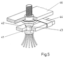
- FIG. 5 shows a two-part anti-rotation protection for the pole bolts pressed into a defined geometric shape 41.
- a fitting 43 is positively inserted into the shape 41 obtained by the press connection of the sleeve-shaped receiving part 2 of the pole bolt 1.
- An abutment 42 with a connecting clip 44 ensures the positive fit of the fitting 43.
Landscapes
- Chemical & Material Sciences (AREA)
- Chemical Kinetics & Catalysis (AREA)
- Electrochemistry (AREA)
- General Chemical & Material Sciences (AREA)
- Engineering & Computer Science (AREA)
- Manufacturing & Machinery (AREA)
- Connection Of Batteries Or Terminals (AREA)
Applications Claiming Priority (2)
| Application Number | Priority Date | Filing Date | Title |
|---|---|---|---|
| DE19541255A DE19541255A1 (de) | 1995-11-06 | 1995-11-06 | Galvanische Zelle |
| DE19541255 | 1995-11-06 |
Publications (2)
| Publication Number | Publication Date |
|---|---|
| EP0772251A1 true EP0772251A1 (fr) | 1997-05-07 |
| EP0772251B1 EP0772251B1 (fr) | 1999-03-24 |
Family
ID=7776705
Family Applications (1)
| Application Number | Title | Priority Date | Filing Date |
|---|---|---|---|
| EP96115126A Expired - Lifetime EP0772251B1 (fr) | 1995-11-06 | 1996-09-20 | Cellule galvanique avec des collecteurs de courant d'électrodes sous forme de fils |
Country Status (3)
| Country | Link |
|---|---|
| US (1) | US5786108A (fr) |
| EP (1) | EP0772251B1 (fr) |
| DE (2) | DE19541255A1 (fr) |
Cited By (2)
| Publication number | Priority date | Publication date | Assignee | Title |
|---|---|---|---|---|
| EP0948065A1 (fr) * | 1998-03-30 | 1999-10-06 | Renata AG | Event de sécurité pour accumulateur ou pile |
| WO2011054586A1 (fr) | 2009-11-06 | 2011-05-12 | Sb Limotive Company Ltd. | Procédé pour relier un pôle de batterie au niveau d'un premier élément de batterie à un pôle de batterie au niveau d'un second élément de batterie, batterie constituée d'éléments de batterie reliés entre eux et système de batteries |
Families Citing this family (6)
| Publication number | Priority date | Publication date | Assignee | Title |
|---|---|---|---|---|
| US6416900B1 (en) * | 2000-07-17 | 2002-07-09 | Hughes Electronics Corp. | Electrochemical cell with graded electrode leads |
| DE102005046256B4 (de) * | 2005-09-27 | 2010-09-30 | Vb Autobatterie Gmbh & Co. Kgaa | Bleibatterie und Kunststoff-Batteriedeckel hierzu |
| US20100323268A1 (en) * | 2009-06-19 | 2010-12-23 | White Box, Inc. | System and method for forming conductors of an energy generating device |
| EP3024065B1 (fr) * | 2014-11-24 | 2018-01-10 | Samsung SDI Co., Ltd. | Raccordement de polarité flexible sur un boîtier de batterie ainsi que procédé |
| CN115011983B (zh) * | 2022-04-20 | 2023-07-04 | 同济大学 | 一种设有多电流输入接线柱的碱水电解槽装置 |
| CN119994400A (zh) * | 2023-11-09 | 2025-05-13 | 麻省固能(上海)新能源科技有限公司 | 用于电池模块的电端子连接器 |
Citations (8)
| Publication number | Priority date | Publication date | Assignee | Title |
|---|---|---|---|---|
| US3625772A (en) * | 1966-08-30 | 1971-12-07 | Mc Donnell Douglas Corp | Electrode-separator combination |
| US4156756A (en) * | 1977-03-02 | 1979-05-29 | Chloride Group Limited | Battery terminals |
| JPS57845A (en) * | 1980-06-04 | 1982-01-05 | Yuasa Battery Co Ltd | Manufacture of nonaqueous electrolyte battery |
| US4328293A (en) * | 1979-10-16 | 1982-05-04 | Automobiles Citroen And Automobiles Peugeot | Electrochemical generators |
| JPS60202662A (ja) * | 1984-03-28 | 1985-10-14 | Shin Kobe Electric Mach Co Ltd | 鉛蓄電池 |
| JPH05290877A (ja) * | 1992-04-02 | 1993-11-05 | Hitachi Maxell Ltd | ニッケル水素蓄電池 |
| JPH06333544A (ja) * | 1993-05-26 | 1994-12-02 | Yuasa Corp | リチウム電池の製造方法 |
| JPH06333545A (ja) * | 1993-05-26 | 1994-12-02 | Yuasa Corp | リチウム電池の製造方法 |
Family Cites Families (7)
| Publication number | Priority date | Publication date | Assignee | Title |
|---|---|---|---|---|
| US1015735A (en) * | 1911-04-25 | 1912-01-23 | Roessler & Hasslacher Chemical | Primary battery. |
| US1371093A (en) * | 1919-07-08 | 1921-03-08 | Philadelphia Storage Battery | Battery connection |
| FR2134256B1 (fr) * | 1971-04-29 | 1974-03-08 | Accumulateurs Fixes | |
| US3956012A (en) * | 1974-06-10 | 1976-05-11 | Scholle Corporation | Storage battery plates of plastic and lead |
| FR2418547A1 (fr) * | 1978-02-28 | 1979-09-21 | Accumulateurs Fixes | Ensemble borne d'accumulateur-faisceau d'electrodes |
| US4521498A (en) * | 1982-07-22 | 1985-06-04 | Gates Energy Products, Inc. | Through-the-partition intercell connection and method |
| US5660946A (en) * | 1996-07-02 | 1997-08-26 | Gnb Technologies, Inc. | Sealed lead-acid cells and batteries having an expandable cover |
-
1995
- 1995-11-06 DE DE19541255A patent/DE19541255A1/de not_active Withdrawn
-
1996
- 1996-09-20 EP EP96115126A patent/EP0772251B1/fr not_active Expired - Lifetime
- 1996-09-20 DE DE59601491T patent/DE59601491D1/de not_active Expired - Fee Related
- 1996-10-29 US US08/741,340 patent/US5786108A/en not_active Expired - Fee Related
Patent Citations (8)
| Publication number | Priority date | Publication date | Assignee | Title |
|---|---|---|---|---|
| US3625772A (en) * | 1966-08-30 | 1971-12-07 | Mc Donnell Douglas Corp | Electrode-separator combination |
| US4156756A (en) * | 1977-03-02 | 1979-05-29 | Chloride Group Limited | Battery terminals |
| US4328293A (en) * | 1979-10-16 | 1982-05-04 | Automobiles Citroen And Automobiles Peugeot | Electrochemical generators |
| JPS57845A (en) * | 1980-06-04 | 1982-01-05 | Yuasa Battery Co Ltd | Manufacture of nonaqueous electrolyte battery |
| JPS60202662A (ja) * | 1984-03-28 | 1985-10-14 | Shin Kobe Electric Mach Co Ltd | 鉛蓄電池 |
| JPH05290877A (ja) * | 1992-04-02 | 1993-11-05 | Hitachi Maxell Ltd | ニッケル水素蓄電池 |
| JPH06333544A (ja) * | 1993-05-26 | 1994-12-02 | Yuasa Corp | リチウム電池の製造方法 |
| JPH06333545A (ja) * | 1993-05-26 | 1994-12-02 | Yuasa Corp | リチウム電池の製造方法 |
Non-Patent Citations (4)
| Title |
|---|
| PATENT ABSTRACTS OF JAPAN vol. 006, no. 060 (E - 102) 17 April 1982 (1982-04-17) * |
| PATENT ABSTRACTS OF JAPAN vol. 010, no. 050 (E - 384) 27 February 1986 (1986-02-27) * |
| PATENT ABSTRACTS OF JAPAN vol. 018, no. 077 (E - 1504) 8 February 1994 (1994-02-08) * |
| PATENT ABSTRACTS OF JAPAN vol. 94, no. 012 * |
Cited By (3)
| Publication number | Priority date | Publication date | Assignee | Title |
|---|---|---|---|---|
| EP0948065A1 (fr) * | 1998-03-30 | 1999-10-06 | Renata AG | Event de sécurité pour accumulateur ou pile |
| US6159630A (en) * | 1998-03-30 | 2000-12-12 | Renata Ag | Safety vent for storage battery or cell |
| WO2011054586A1 (fr) | 2009-11-06 | 2011-05-12 | Sb Limotive Company Ltd. | Procédé pour relier un pôle de batterie au niveau d'un premier élément de batterie à un pôle de batterie au niveau d'un second élément de batterie, batterie constituée d'éléments de batterie reliés entre eux et système de batteries |
Also Published As
| Publication number | Publication date |
|---|---|
| EP0772251B1 (fr) | 1999-03-24 |
| DE59601491D1 (de) | 1999-04-29 |
| US5786108A (en) | 1998-07-28 |
| DE19541255A1 (de) | 1997-05-07 |
Similar Documents
| Publication | Publication Date | Title |
|---|---|---|
| DE60313313T2 (de) | Elektrochemisches bündel | |
| DE112012003782B4 (de) | Verpressungsstruktur für Metallelemente und Sammelschiene, welche diese verwendet | |
| DE102011013845B4 (de) | Batteriemodul und vorrichtung sowie verfahren zum zusammenbauen eines batteriemoduls | |
| EP2639857B1 (fr) | Système de liaison pour un dispositif d'accumulation d'énergie et dispositif d'accumulation d'énergie doté du système de liaison | |
| EP2727172A1 (fr) | Dispositif d'accumulation électrique | |
| DE112018003895T5 (de) | Energiespeichereinrichtung | |
| EP2497134B1 (fr) | Procédé pour relier un pôle de batterie au niveau d'un premier élément de batterie à un pôle de batterie au niveau d'un second élément de batterie, batterie constituée d'éléments de batterie reliés entre eux et système de batteries | |
| DE10105877A1 (de) | Kompakte Lithium-Ion-Batterie und Verfahren zu ihrerHerstellung | |
| DE102012207889A1 (de) | Batteriemodul und Verfahren zum Herstellen desselben | |
| DE10100626A1 (de) | Lithium-Ion-Batterie und Behälter | |
| WO2008058758A1 (fr) | Élément de batterie à système d'éléments de contact | |
| DE102022103728B3 (de) | Batteriezelle | |
| WO2011060969A1 (fr) | Connecteur d'éléments de batterie | |
| EP1555704B1 (fr) | Accumulateur et méthode de sa fabrication | |
| DE10046885B4 (de) | Sekundärbatterie mit einer Vielzahl von durch einen Sammelanschluß verbundenen Elektrodenanschlüssen und Herstellungsverfahren dafür | |
| DE102015007615A1 (de) | Verbindungselement zur elektrischen Verschaltung von Einzelzellen, Zellblock und elektrische Batterie | |
| DE102013016617A1 (de) | Batterie mit einer Vielzahl von Batterieeinzelzellen | |
| WO2020099359A1 (fr) | Procédé de connexion par liaison de matière d'une borne d'un élément de batterie avec au moins un connecteur d'élément et module de batterie | |
| EP0772251B1 (fr) | Cellule galvanique avec des collecteurs de courant d'électrodes sous forme de fils | |
| DE102016106620A1 (de) | Elektrische Hochstrom-Fügestelle, die eine Teilmontage beseitigt | |
| DE102014015237A1 (de) | Batterie und Verfahren zur Herstellung einer solchen Batterie | |
| EP2524407B1 (fr) | Batterie, système de batteries et procédé de connexion d'une pluralité de batteries | |
| EP4084202A1 (fr) | Agencement de connecteur d'élément de batterie, module de batterie, dispositif batterie pourvu d'au moins deux modules de batterie et procédé de fabrication du dispositif batterie | |
| DE102017220505B4 (de) | Anschlusselement zur mechanischen und elektrischen Verbindung mit einem Kontaktelement einer elektrischen Speicherzelle, insbesondere einer Kontaktfahne einer Pouch-Zelle, sowie elektrisches Speicherzellenmodul | |
| DE102016208589A1 (de) | Elektrodenanordnung einer Batteriezelle, Elektrodenschicht und Batteriezelle sowie Verfahren zu deren Herstellung |
Legal Events
| Date | Code | Title | Description |
|---|---|---|---|
| PUAI | Public reference made under article 153(3) epc to a published international application that has entered the european phase |
Free format text: ORIGINAL CODE: 0009012 |
|
| AK | Designated contracting states |
Kind code of ref document: A1 Designated state(s): BE CH DE FR GB IT LI SE |
|
| 17P | Request for examination filed |
Effective date: 19970523 |
|
| 17Q | First examination report despatched |
Effective date: 19980120 |
|
| GRAG | Despatch of communication of intention to grant |
Free format text: ORIGINAL CODE: EPIDOS AGRA |
|
| GRAG | Despatch of communication of intention to grant |
Free format text: ORIGINAL CODE: EPIDOS AGRA |
|
| GRAH | Despatch of communication of intention to grant a patent |
Free format text: ORIGINAL CODE: EPIDOS IGRA |
|
| GRAH | Despatch of communication of intention to grant a patent |
Free format text: ORIGINAL CODE: EPIDOS IGRA |
|
| GRAA | (expected) grant |
Free format text: ORIGINAL CODE: 0009210 |
|
| AK | Designated contracting states |
Kind code of ref document: B1 Designated state(s): BE CH DE FR GB IT LI SE |
|
| PG25 | Lapsed in a contracting state [announced via postgrant information from national office to epo] |
Ref country code: SE Free format text: THE PATENT HAS BEEN ANNULLED BY A DECISION OF A NATIONAL AUTHORITY Effective date: 19990324 Ref country code: IT Free format text: LAPSE BECAUSE OF FAILURE TO SUBMIT A TRANSLATION OF THE DESCRIPTION OR TO PAY THE FEE WITHIN THE PRESCRIBED TIME-LIMIT;WARNING: LAPSES OF ITALIAN PATENTS WITH EFFECTIVE DATE BEFORE 2007 MAY HAVE OCCURRED AT ANY TIME BEFORE 2007. THE CORRECT EFFECTIVE DATE MAY BE DIFFERENT FROM THE ONE RECORDED. Effective date: 19990324 |
|
| REG | Reference to a national code |
Ref country code: CH Ref legal event code: EP |
|
| REF | Corresponds to: |
Ref document number: 59601491 Country of ref document: DE Date of ref document: 19990429 |
|
| GBT | Gb: translation of ep patent filed (gb section 77(6)(a)/1977) |
Effective date: 19990412 |
|
| ET | Fr: translation filed | ||
| PLBE | No opposition filed within time limit |
Free format text: ORIGINAL CODE: 0009261 |
|
| STAA | Information on the status of an ep patent application or granted ep patent |
Free format text: STATUS: NO OPPOSITION FILED WITHIN TIME LIMIT |
|
| 26N | No opposition filed | ||
| PG25 | Lapsed in a contracting state [announced via postgrant information from national office to epo] |
Ref country code: LI Free format text: LAPSE BECAUSE OF NON-PAYMENT OF DUE FEES Effective date: 20000930 Ref country code: CH Free format text: LAPSE BECAUSE OF NON-PAYMENT OF DUE FEES Effective date: 20000930 |
|
| REG | Reference to a national code |
Ref country code: CH Ref legal event code: PL |
|
| PGFP | Annual fee paid to national office [announced via postgrant information from national office to epo] |
Ref country code: BE Payment date: 20010810 Year of fee payment: 6 |
|
| PGFP | Annual fee paid to national office [announced via postgrant information from national office to epo] |
Ref country code: GB Payment date: 20010919 Year of fee payment: 6 |
|
| REG | Reference to a national code |
Ref country code: GB Ref legal event code: IF02 |
|
| PGFP | Annual fee paid to national office [announced via postgrant information from national office to epo] |
Ref country code: DE Payment date: 20020914 Year of fee payment: 7 |
|
| PG25 | Lapsed in a contracting state [announced via postgrant information from national office to epo] |
Ref country code: GB Free format text: LAPSE BECAUSE OF NON-PAYMENT OF DUE FEES Effective date: 20020920 |
|
| PG25 | Lapsed in a contracting state [announced via postgrant information from national office to epo] |
Ref country code: BE Free format text: LAPSE BECAUSE OF NON-PAYMENT OF DUE FEES Effective date: 20020930 |
|
| BERE | Be: lapsed |
Owner name: *VARTA BATTERIE A.G. Effective date: 20020930 |
|
| GBPC | Gb: european patent ceased through non-payment of renewal fee |
Effective date: 20020920 |
|
| PGFP | Annual fee paid to national office [announced via postgrant information from national office to epo] |
Ref country code: FR Payment date: 20030929 Year of fee payment: 8 |
|
| PG25 | Lapsed in a contracting state [announced via postgrant information from national office to epo] |
Ref country code: DE Free format text: LAPSE BECAUSE OF NON-PAYMENT OF DUE FEES Effective date: 20040401 |
|
| PG25 | Lapsed in a contracting state [announced via postgrant information from national office to epo] |
Ref country code: FR Free format text: LAPSE BECAUSE OF NON-PAYMENT OF DUE FEES Effective date: 20050531 |
|
| REG | Reference to a national code |
Ref country code: FR Ref legal event code: ST |