EP4084202A1 - Agencement de connecteur d'élément de batterie, module de batterie, dispositif batterie pourvu d'au moins deux modules de batterie et procédé de fabrication du dispositif batterie - Google Patents
Agencement de connecteur d'élément de batterie, module de batterie, dispositif batterie pourvu d'au moins deux modules de batterie et procédé de fabrication du dispositif batterie Download PDFInfo
- Publication number
- EP4084202A1 EP4084202A1 EP22020039.8A EP22020039A EP4084202A1 EP 4084202 A1 EP4084202 A1 EP 4084202A1 EP 22020039 A EP22020039 A EP 22020039A EP 4084202 A1 EP4084202 A1 EP 4084202A1
- Authority
- EP
- European Patent Office
- Prior art keywords
- pole
- battery
- frame
- battery cell
- electrically
- Prior art date
- Legal status (The legal status is an assumption and is not a legal conclusion. Google has not performed a legal analysis and makes no representation as to the accuracy of the status listed.)
- Pending
Links
Images

Classifications
-
- H—ELECTRICITY
- H01—ELECTRIC ELEMENTS
- H01M—PROCESSES OR MEANS, e.g. BATTERIES, FOR THE DIRECT CONVERSION OF CHEMICAL ENERGY INTO ELECTRICAL ENERGY
- H01M50/00—Constructional details or processes of manufacture of the non-active parts of electrochemical cells other than fuel cells, e.g. hybrid cells
- H01M50/20—Mountings; Secondary casings or frames; Racks, modules or packs; Suspension devices; Shock absorbers; Transport or carrying devices; Holders
- H01M50/204—Racks, modules or packs for multiple batteries or multiple cells
- H01M50/207—Racks, modules or packs for multiple batteries or multiple cells characterised by their shape
- H01M50/213—Racks, modules or packs for multiple batteries or multiple cells characterised by their shape adapted for cells having curved cross-section, e.g. round or elliptic
-
- H—ELECTRICITY
- H01—ELECTRIC ELEMENTS
- H01M—PROCESSES OR MEANS, e.g. BATTERIES, FOR THE DIRECT CONVERSION OF CHEMICAL ENERGY INTO ELECTRICAL ENERGY
- H01M50/00—Constructional details or processes of manufacture of the non-active parts of electrochemical cells other than fuel cells, e.g. hybrid cells
- H01M50/50—Current conducting connections for cells or batteries
- H01M50/502—Interconnectors for connecting terminals of adjacent batteries; Interconnectors for connecting cells outside a battery casing
-
- H—ELECTRICITY
- H01—ELECTRIC ELEMENTS
- H01M—PROCESSES OR MEANS, e.g. BATTERIES, FOR THE DIRECT CONVERSION OF CHEMICAL ENERGY INTO ELECTRICAL ENERGY
- H01M50/00—Constructional details or processes of manufacture of the non-active parts of electrochemical cells other than fuel cells, e.g. hybrid cells
- H01M50/50—Current conducting connections for cells or batteries
- H01M50/502—Interconnectors for connecting terminals of adjacent batteries; Interconnectors for connecting cells outside a battery casing
- H01M50/503—Interconnectors for connecting terminals of adjacent batteries; Interconnectors for connecting cells outside a battery casing characterised by the shape of the interconnectors
-
- H—ELECTRICITY
- H01—ELECTRIC ELEMENTS
- H01M—PROCESSES OR MEANS, e.g. BATTERIES, FOR THE DIRECT CONVERSION OF CHEMICAL ENERGY INTO ELECTRICAL ENERGY
- H01M50/00—Constructional details or processes of manufacture of the non-active parts of electrochemical cells other than fuel cells, e.g. hybrid cells
- H01M50/50—Current conducting connections for cells or batteries
- H01M50/502—Interconnectors for connecting terminals of adjacent batteries; Interconnectors for connecting cells outside a battery casing
- H01M50/509—Interconnectors for connecting terminals of adjacent batteries; Interconnectors for connecting cells outside a battery casing characterised by the type of connection, e.g. mixed connections
- H01M50/51—Connection only in series
-
- H—ELECTRICITY
- H01—ELECTRIC ELEMENTS
- H01M—PROCESSES OR MEANS, e.g. BATTERIES, FOR THE DIRECT CONVERSION OF CHEMICAL ENERGY INTO ELECTRICAL ENERGY
- H01M50/00—Constructional details or processes of manufacture of the non-active parts of electrochemical cells other than fuel cells, e.g. hybrid cells
- H01M50/50—Current conducting connections for cells or batteries
- H01M50/502—Interconnectors for connecting terminals of adjacent batteries; Interconnectors for connecting cells outside a battery casing
- H01M50/509—Interconnectors for connecting terminals of adjacent batteries; Interconnectors for connecting cells outside a battery casing characterised by the type of connection, e.g. mixed connections
- H01M50/512—Connection only in parallel
-
- H—ELECTRICITY
- H01—ELECTRIC ELEMENTS
- H01M—PROCESSES OR MEANS, e.g. BATTERIES, FOR THE DIRECT CONVERSION OF CHEMICAL ENERGY INTO ELECTRICAL ENERGY
- H01M50/00—Constructional details or processes of manufacture of the non-active parts of electrochemical cells other than fuel cells, e.g. hybrid cells
- H01M50/50—Current conducting connections for cells or batteries
- H01M50/502—Interconnectors for connecting terminals of adjacent batteries; Interconnectors for connecting cells outside a battery casing
- H01M50/514—Methods for interconnecting adjacent batteries or cells
- H01M50/517—Methods for interconnecting adjacent batteries or cells by fixing means, e.g. screws, rivets or bolts
-
- Y—GENERAL TAGGING OF NEW TECHNOLOGICAL DEVELOPMENTS; GENERAL TAGGING OF CROSS-SECTIONAL TECHNOLOGIES SPANNING OVER SEVERAL SECTIONS OF THE IPC; TECHNICAL SUBJECTS COVERED BY FORMER USPC CROSS-REFERENCE ART COLLECTIONS [XRACs] AND DIGESTS
- Y02—TECHNOLOGIES OR APPLICATIONS FOR MITIGATION OR ADAPTATION AGAINST CLIMATE CHANGE
- Y02E—REDUCTION OF GREENHOUSE GAS [GHG] EMISSIONS, RELATED TO ENERGY GENERATION, TRANSMISSION OR DISTRIBUTION
- Y02E60/00—Enabling technologies; Technologies with a potential or indirect contribution to GHG emissions mitigation
- Y02E60/10—Energy storage using batteries
Definitions
- the present invention relates to a battery cell connection device for connecting battery cells, and a battery module with the battery cell connection device and a single-pole battery cell, in particular a single-pole high-voltage battery cell, a battery device with at least two such battery modules and a method for producing a battery device from a plurality of battery modules.
- the battery device is in particular a drive battery device for driving an electric motor vehicle or a hybrid motor vehicle with an electric motor and an internal combustion engine.
- DE 10 2014 222 552 A1 discloses a lithium-ion battery cell containing at least one electrochemical component and at least one operating device, wherein the at least one electrochemical component and the at least one operating device can be reversibly connected to one another and reversibly detached from one another.
- the DE 10 2018 222 458 A1 a contacting device for a battery cell for a battery of a motor vehicle, having a housing made of an electrically insulating material and an interconnection device at least partially enclosed by the housing.
- the cell connector for the electrically conductive connection of round cells of a battery for a motor vehicle.
- the cell connector comprises a plurality of electrically conductive contact elements for the end-side connection of two of the round cells in series connection, the contact elements each having a bottom contact surface for producing a have a material connection with a respective cell cap of the round cells and spring arms for producing a non-positive connection with a respective cell cup of the round cells.
- the cell connector comprises a plurality of electrically conductive connecting webs which connect the contact elements arranged in groups to one another. The contact elements and connecting webs are made from a common stamped and bent part.
- the object of the present invention is to provide an improved battery cell connection device which, in particular, allows battery cells to be connected according to a modular principle to form a battery device.
- the object is achieved by means of a battery cell connection device according to patent claim 1, by a battery module according to patent claim 7, a battery device according to claim 9 and a method for manufacturing a battery device according to claim 12
- the battery cell connection device has the advantage that it allows a battery module to be produced very easily from the battery cell connection device and a corresponding single-pole battery cell and then assembled into a battery device using the modular principle with serial and parallel interconnections of the individual battery modules. This makes it possible to produce battery devices using the modular principle, in which a loadable installation space in a vehicle can be determined, even in an early concept phase. This means that development costs can be saved. Costly and project-specific battery cell contacting solutions can be reduced or even eliminated.
- a battery module is provided with such a battery cell connection device and a single-pole battery cell with a first pole and a second pole, the battery cell being accommodated with the section with the two poles in the receptacle of the frame of the battery cell connection device and the frame making electrical contact with the first pole and the tab member electrically contacts the second pole.
- the manufacturing time and the risk of rejects in the critical battery cell contacting in battery production and assembly can be significantly reduced.
- the tolerances of the battery cells can be captured by the modular design.
- the battery cell manufacturers can adapt the tolerances of the battery cells to the kit of battery modules.
- the current-carrying capacity, thermal design, air and creepage distances can be ensured or standardized by means of the battery cell connection device and the battery modules resulting therefrom and do not always have to be recalculated again. This also results in savings in development costs.
- a battery device which has several of the battery modules and at least one electrically insulating connecting element, wherein the electrically insulating connecting element connects at least two of the battery modules to one another in such a way that the frames of the two battery modules are electrically insulated from one another, the tab element of one battery module being connected electrically contacts the frame of the other battery module with its outer end to provide a serial connection of the two battery modules.
- the frame is designed in such a way that it can be electrically connected to a further frame of a battery cell connection device on at least one or on at least two sides, e.g. at least two opposite sides.
- the battery module can be very easily connected to other battery modules, in particular connected in parallel.
- the frame is designed, for example, to be connectable on the respective side to the other frame by screwing, pinning, riveting, welding, plugging, latching and/or gluing, in particular to be electrically conductively connectable.
- the frame has a fastening section on the respective side for fastening a further frame, with which the frame can be plugged together with the other frame and preferably additionally screwed, pinned, riveted, welded, latched and/or glued.
- the fastening section has, for example, a bore or threaded bore.
- Such attachment sections form simple, repeated connection options for the battery modules each other, and thus the realization of a modular principle.
- the attachment sections can also be used, for example, to attach an electrically insulating connection element, which is used in a series connection. This allows costs to be reduced.
- the fastening section has a stepped projection, which projects laterally on the frame and can be received or inserted in a recess of the other frame that corresponds to the stepped projection.
- the fastening section can have a recess formed on the top or bottom of the frame, into which a corresponding, stepped projection of the other frame can be received or inserted.
- the frame has an access opening at an upper end of the receptacle as access for electrically contacting the second pole of the battery cell that can be accommodated in the receptacle.
- the tab element has an inner end with which the tab element can be electrically conductively connected to the second pole through the access opening, in particular can be welded to the second pole.
- the tab element has an outer end with which the tab element protrudes laterally beyond the frame for electrical contacting with a first pole of a further battery cell and in particular a further frame connected to the frame of a further battery cell connection device.
- the tab member has the advantage of providing a very simple and reliable electrical connection.
- the receptacle is designed as a receptacle sleeve for positively and/or non-positively retaining the section of the battery cell with its first and second pole.
- the receiving sleeve can preferably also be welded to the first pole, in particular an annular first pole, on the periphery of the battery cell in order to provide a defined electrically conductive connection of the frame to the first pole.
- the battery cell poled on one side is a round battery cell poled on one side, in particular a high-voltage round battery cell poled on one side.
- Such high-voltage battery cells are used for drive battery devices, for example in electric vehicles.
- the first pole of the battery cell can be ring-shaped and the second pole can be provided within the ring-shaped first pole, with the first and second poles being electrically insulated from one another.
- the first pole can be a negative pole and the second pole can be a positive pole or the first pole can be a positive pole and the second pole can be a negative pole.
- the electrically insulating connecting element has a web, which is arranged between the two frames of the battery modules that are connected to one another in series and separates them from one another and thereby electrically insulates them from one another.
- the web can easily be bridged by the tab element of a battery module in order to provide a serial connection of two battery modules by means of the tab element.
- the connecting element has, at its two ends on both sides of the bar, a fastening section that corresponds to the fastening section of the respective frame provided on the bar.
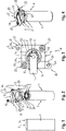
- FIG 1 1 shows a greatly simplified, purely schematic sectional view of a single-pole battery cell 1, for example a single-pole high-voltage battery cell, for a battery device.
- battery cells 1 are connected to a battery cell connection device in order to provide a respective battery module.
- the battery module can be interconnected with other such battery modules in a kind of modular system to form a desired battery device, as in exemplary embodiments of battery devices in FIGS Figures 5 to 8 is shown.
- Such a battery device made up of a plurality of battery modules connected to one another in series and/or in parallel can be provided, for example, as a drive battery device for driving an electric vehicle.
- drive battery devices are also referred to as high-voltage battery devices and are used as mobile electrical energy stores, in particular for driving electric vehicles and in particular for supplying the electric motors of the electric vehicles with energy.
- the battery cell 1 for example in the form of a single-pole battery round cell as in figure 1 shown, has a plus pole 2 and a minus pole 3 on one side or face here.
- the negative pole 3 is, for example, ring-shaped, with the positive pole 2 being arranged inside the ring-shaped negative pole 3 .
- the negative pole 3 and the positive pole 2 are electrically isolated from each other.
- the positive pole can be ring-shaped and the negative pole can be arranged inside the ring-shaped positive pole, with both poles also being electrically insulated from one another.
- the invention is not limited to round battery cells.
- the battery cells 1 can have any other shape, for example a square shape, etc., depending on the function and intended use.
- FIGs 2, 3 and 4 show an embodiment of a battery module 4 according to the invention, which consists of the battery cell 1 according to figure 1 and a battery cell connection device 5 consists.
- the battery module 4 is shown in an exploded view.
- figure 3 again shows a plan view of the battery module 4 and figure 4 a perspective view of the battery module 4.
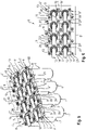
- FIG 5 is a perspective view and in figure 6 is a plan view of an embodiment of a battery device 6 is shown, which consists of several in the Figures 2 to 4 Battery modules 4 shown is assembled.
- the battery cell connection device 5, as in the Figures 2 to 6 shown has a frame 7 with a receptacle 8 on its underside.
- the frame 7 with its mount 8 consists of an electrically conductive material or an electrically conductive material combination.
- the frame 7 with its receptacle 8 is made of metal, such as aluminum or an aluminum alloy, etc.
- the frame 7 with its recording 8, as in the Figures 2 to 6 Be formed, for example, as a metal casting.
- the receptacle 8 on the underside 9 of the frame 7 is designed, for example, as a receiving sleeve for receiving a section of the battery cell 1 with the negative pole 3 and the positive pole 2.
- the battery cell 1 is in the receptacle 8 and more precisely in the receiving sleeve, for example positively and / or non-positively added.
- the receiving sleeve is designed as a cylindrical receiving sleeve for receiving the section of the cylindrically shaped round battery cell which has the negative pole 3 and the positive pole 2.
- the round cell battery can be accommodated in the receiving sleeve, for example, in a form-fitting and/or force-fitting manner.
- the receptacle 8 is then attached to the ring-shaped pole, here the negative pole 3, and in particular to the circumference of the ring-shaped pole, for example by welding, to form an electrically conductive connection with the ring-shaped pole, here the negative pole 3, of the battery cell 1 to provide.
- the frame 7 with the receptacle 8 thus forms the negative pole 3 of the battery cell 1 in the exemplary embodiment.
- the frame 7 with the receptacle 8 forms or functions as the negative pole 3 of the battery cell connection device 5.
- the receptacle 8 of the frame 7 of the battery cell connection device 5 can, for example, be partially or completely circumferentially welded to the ring-shaped pole, here the negative pole 3, of the battery cell 1, for example by means of laser welding.
- the weld seam 10 running around the circumference of the receptacle 8, with which the receptacle 8 is connected to the negative pole 3 of the battery cell 1 in order to provide an electrically conductive connection between the negative pole 3 and the frame 7 with its receptacle 8.
- Welding the receptacle 8 to the circumference of the annular negative pole 3 of the battery cell 1 has the advantage of high process reliability compared to welding to the flange of a cell can of a battery cell, as in the following Figures 9 and 10 is shown.
- the frame 7 also has an access opening 11 at the end of the receptacle 8 as access to the other pole, here the positive pole 2, of the portion of the battery cell 1 accommodated in the receptacle 8.
- the positive pole 2 can be used as a Battery cell cover of the battery cell 1 can be provided, as in figure 2 is indicated.
- the battery cell connection device 5 has a tab element 12 made of an electrically conductive material, for example made of metal, eg aluminum or an aluminum alloy etc.
- the tab element 12 is fastened with a section on the frame 7, for example on the upper side 13 of the frame 7, in an electrically insulating manner.
- the tab element 12 is molded onto the upper side 13 of the frame 7, for example by means of an electrically insulating plastic 14, in order to electrically insulate the tab element 12 from the negative pole 3 of the battery cell 1.
- other sections of the frame 7 can optionally be coated with the electrically insulating plastic 14, such as in FIGS Figures 2, 3 and 4 is shown.
- the tab element 12 With an inner end 15, the tab element 12 is attached to the pole, here the positive pole 2, of the battery cell 1 in an electrically conductive manner.
- the tab element 12 is welded with its inner end 15 to the positive pole 3, for example by means of laser welding, to provide the electrically conductive connection of the tab element 12 to the positive pole 2.
- the weld point 16 of the tab element 12 with the positive pole 2 is shown.
- the tab element 12 thus forms the positive pole 2 of the battery cell 1 .
- the tab element 12 forms or functions as the positive pole of the battery cell connection device 5.
- the positive pole and the negative pole of the battery cell connection device 5 are electrically insulated from one another by the additionally applied electrically insulating layer, e.g. in the form of the electrically insulating plastic 14
- the outer end 16 of the tab member 12, as shown in FIGS Figures 2 to 6 is shown, preferably projecting laterally outwards over the battery cell connection device 5 or its frame 7 for electrical contacting of the frame 7 of the battery cell connection device 5 of an adjacent battery module 4.
- the tab element 12 can rest with its outer end 17, for example, on a region of the frame 7 acting as a negative pole that is not additionally provided with electrical insulation, or alternatively can be attached to it in an electrically conductive manner. As a result, the outer end 17 of the tab element 12 can make electrical contact with the frame 7 of the adjacent battery module 4 and an electrically conductive connection can thus be established between the positive pole 2 of the battery cell 1 and the negative pole 3 of the adjacent battery cell 1 .
- a connecting element 18 is provided between the two frames 7 of the battery cell connecting devices 5 made of an electrically insulating material or an electrically insulating material combination.
- the connecting element 18 prevents the two frames 7 from directly abutting one another and from being able to make electrical contact as a result.
- This connecting element 18 is connected to the respective frame 7, for example screwed, riveted, pinned, latched, plugged together, clamped, glued and/or welded, etc.
- the invention is not limited to the fastening methods mentioned for fastening the frame 7 and the connecting element 18 to one another limited.
- the connecting element 18 is, for example, plugged together with the frame 7 of the respective battery cell connecting device 5 and additionally screwed.
- a plurality of battery modules 4 can be connected in series, ie in series, as shown in FIGS Figures 5 and 6 is shown.
- the frames 7 of the adjacent battery modules 4 which each depict the negative pole 3 of their associated battery cell 1, are brought into contact with one another and connected, for example plugged together and additionally screwed together.
- the battery cell pair 1, 1 connected in parallel by its two frames 7 acting as negative poles is again, as in FIGS Figures 5 and 6 is shown, connected in series, ie in series, with an adjacent pair of battery cells 1, 1.
- the electrically insulating connecting element 18 is provided between the two pairs of battery cells 1, 1 and, more precisely, between their two pairs of frames 7, 7. This electrically insulating connecting element 18 connects the pairs of frames 7, 7 of the two pairs of battery cells 1, 1 in such a way that the two pairs of frames 7, 7 are electrically insulated from one another.
- the battery modules 4 with their battery cells 1 and the associated battery cell connection devices 5 can very easily be connected in series with one another as required, ie in series and/or in parallel with one another to form a battery device, such as the battery device 6 in the Figures 5 and 6 or the following one Figures 7 and 8 be interconnected.
- the embodiment of the battery cell connecting device 5 shown is the frame 7, for example, square and preferably formed with a substantially planar or level upper side 13.
- the frame 7 is designed in such a way that it is connected to another frame 7 of another on two opposite sides 19, 19' Battery module 4 can be connected and connected in parallel by the frame 7 being plugged together with the other frame 7, for example, and optionally screwed in addition, for example.
- each frame 7 has a stepped projection 21 on at least one side 19 at one end 20 for insertion into a corresponding recess 22 on the opposite side of the other frame 7 . Furthermore, the frame 7 has a recess 22 on the side 19 at the respective other end 23 for inserting a corresponding stepped projection 21 on the opposite side of the other frame 7 . In order to connect more than two frames 7, 7 to one another, the respective frame 7 has the stepped projection 21 on two opposite sides 19 and 19' at two diagonally opposite ends and the recess 22 on the other two diagonally opposite ends.
- the recess 22 is designed to correspond to the stepped projection 21 of the other frame 7 to be received in the recess, so that two frames 7, 7 that are connected to one another and more precisely plugged together form, for example, an essentially flush upper side with a preferably flat or planar surface, such as in the Figures 5 and 6 and the following Figures 7 and 8 is shown.
- the respective stepped projection 21 is provided with a threaded bore 24 and the recess 22 with a suitable bore 25 or also a suitable threaded bore, so that the stepped projection 21 of the other frame 7 accommodated in the recess 22 of the frame 7 is screwed to it can be.
- screwing pinning or riveting etc. of the two frames 7, 7 and their recesses 22 and stepped projections 21 can be provided. In this way, several battery modules 4 with their frames 7 can be connected to one another very easily and in parallel in a kind of modular principle be interconnected.
- the respective connecting element 18 can be designed in such a way that it has a web 26 in the longitudinal direction, which in the assembled state runs between the opposite frames 7 of the respective battery modules 4 and separates them from one another in order to electrically insulate them from one another.
- the connecting element 18 has a first and second fastening section 27, 28 at its two longitudinal ends on both sides of the web 26, for fastening the two outermost battery modules 4 lying opposite to the web 26 and their frames 7, as in FIGS Figures 5 and 6 is shown.
- the first fastening section 27 is designed, for example, as a reversely stepped projection for resting on the stepped projection 21 of the frame 7 of the outermost battery module 4.
- the reversely stepped projection of the connecting element 18 forms, for example, a planar or flat surface with the upper side 19 of the frame 7, as in the Figures 5 and 6 is shown.
- the first fastening section 27 can also be screwed, pinned or riveted to the stepped projection 21 of the frame 7, for example, etc.
- the second fastening section 28 of the connecting element 18 is designed as a stepped projection for receiving in the recess 22 of the frame 7 of the outermost battery module 7 on the other side of the web 26.
- the second fastening section 28 can also be screwed, pinned or riveted to the frame 7 and its recess 22, for example, as in FIGS Figures 5 and 6 is shown.
- the exemplary embodiment shown for a battery device 6 has, for example, a 4S 2P battery cell circuit. This means that in the total of eight battery cells 1, two battery cells each are connected in parallel and four of these battery cell pairs are connected in series, ie in series.
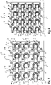
- FIG 7 is a plan view of a battery device 6 with, for example, twelve battery modules 4, wherein battery modules 4, as in the Figures 2 to 4 are shown are used.
- the battery device in figure 7 has, for example, a 4S 3P battery cell circuit. This means that in the total of twelve battery cells 1, three battery cells 1 are connected in parallel and four of these three pairs of battery cells are connected in series, ie in series.
- FIG 8 a top view of a battery device 6 with, for example, sixteen battery modules 4 is shown, with battery modules 4 as shown in FIGS Figures 2 to 4 are shown are used.
- the battery device 6 in figure 8 has, for example, a 4S 4P battery cell circuit. This means that in the total of sixteen battery cells 1, four battery cells each are connected in parallel and four of these battery cell pairs of four are connected in series, ie in series.
- a battery device 6 can be provided with any number of such battery modules 4 and any serial and parallel connection of battery modules 4 of the battery device 6 can be generated, depending on the function and purpose.
- FIG 9 is, as previously described, a section of a battery cell with a cell can with a flange 29, and in figure 10 a section of two interconnected battery cells with a respective cell can with a flange 29 is shown.
- the welding of the recording Battery cell connection device on the circumference of the annular negative pole of the battery cell at the in Figures 1 to 8 battery modules shown the advantage of high process reliability, compared to welding at the flange 29 of a cell can, as in the n Figures 9 and 10 is shown surrounding a silicone gasket 30 .
Landscapes
- Chemical & Material Sciences (AREA)
- Chemical Kinetics & Catalysis (AREA)
- Electrochemistry (AREA)
- General Chemical & Material Sciences (AREA)
- Connection Of Batteries Or Terminals (AREA)
- Battery Mounting, Suspending (AREA)
Applications Claiming Priority (1)
| Application Number | Priority Date | Filing Date | Title |
|---|---|---|---|
| DE102021110819.5A DE102021110819A1 (de) | 2021-04-28 | 2021-04-28 | Batteriezellenverbindungseinrichtung, Batteriemodul, Batterievorrichtung mit wenigstens zwei Batteriemodulen und Verfahren zum Herstellen einer Batterievorrichtung |
Publications (1)
| Publication Number | Publication Date |
|---|---|
| EP4084202A1 true EP4084202A1 (fr) | 2022-11-02 |
Family
ID=80447237
Family Applications (1)
| Application Number | Title | Priority Date | Filing Date |
|---|---|---|---|
| EP22020039.8A Pending EP4084202A1 (fr) | 2021-04-28 | 2022-02-08 | Agencement de connecteur d'élément de batterie, module de batterie, dispositif batterie pourvu d'au moins deux modules de batterie et procédé de fabrication du dispositif batterie |
Country Status (2)
| Country | Link |
|---|---|
| EP (1) | EP4084202A1 (fr) |
| DE (1) | DE102021110819A1 (fr) |
Families Citing this family (2)
| Publication number | Priority date | Publication date | Assignee | Title |
|---|---|---|---|---|
| DE102023127572B3 (de) | 2023-10-10 | 2024-05-08 | Dr. Ing. H.C. F. Porsche Aktiengesellschaft | Verfahren zum Herstellen einer Rundzelle einer Traktionsbatterie |
| DE102024131906A1 (de) * | 2024-10-31 | 2026-04-30 | UNIVERSAL TRANSMISSIONS Gesellschaft für Antriebstechnik mbH | Batteriezelle und Batteriemodul |
Citations (5)
| Publication number | Priority date | Publication date | Assignee | Title |
|---|---|---|---|---|
| US20090111015A1 (en) * | 2006-05-11 | 2009-04-30 | Johnson Controls - Saft Advanced Power Solutions Llc | Modular battery system |
| DE102014222552A1 (de) | 2014-11-05 | 2016-05-12 | Robert Bosch Gmbh | Batteriezelle und Batteriesystem mit reversibel miteinander verbindbarer und voneinander lösbarer Komponenten |
| CN110534690A (zh) * | 2019-09-06 | 2019-12-03 | 华霆(合肥)动力技术有限公司 | 极耳固定装置、极耳盖帽、电池及焊接方法 |
| WO2020094218A1 (fr) | 2018-11-06 | 2020-05-14 | Lisa Dräxlmaier GmbH | Connecteur de cellules servant à relier de manière électroconductrice des cellules rondes d'une batterie pour un véhicule automobile, et procédé de fabrication d'une batterie pour un véhicule automobile |
| DE102018222458A1 (de) | 2018-12-20 | 2020-06-25 | Audi Ag | Kontaktierungsvorrichtung für eine Batteriezelle für eine Batterie eines Kraftfahrzeugs |
-
2021
- 2021-04-28 DE DE102021110819.5A patent/DE102021110819A1/de active Pending
-
2022
- 2022-02-08 EP EP22020039.8A patent/EP4084202A1/fr active Pending
Patent Citations (5)
| Publication number | Priority date | Publication date | Assignee | Title |
|---|---|---|---|---|
| US20090111015A1 (en) * | 2006-05-11 | 2009-04-30 | Johnson Controls - Saft Advanced Power Solutions Llc | Modular battery system |
| DE102014222552A1 (de) | 2014-11-05 | 2016-05-12 | Robert Bosch Gmbh | Batteriezelle und Batteriesystem mit reversibel miteinander verbindbarer und voneinander lösbarer Komponenten |
| WO2020094218A1 (fr) | 2018-11-06 | 2020-05-14 | Lisa Dräxlmaier GmbH | Connecteur de cellules servant à relier de manière électroconductrice des cellules rondes d'une batterie pour un véhicule automobile, et procédé de fabrication d'une batterie pour un véhicule automobile |
| DE102018222458A1 (de) | 2018-12-20 | 2020-06-25 | Audi Ag | Kontaktierungsvorrichtung für eine Batteriezelle für eine Batterie eines Kraftfahrzeugs |
| CN110534690A (zh) * | 2019-09-06 | 2019-12-03 | 华霆(合肥)动力技术有限公司 | 极耳固定装置、极耳盖帽、电池及焊接方法 |
Also Published As
| Publication number | Publication date |
|---|---|
| DE102021110819A1 (de) | 2022-11-03 |
Similar Documents
| Publication | Publication Date | Title |
|---|---|---|
| DE102012101771B4 (de) | Klemmenanschlusseinrichtung für ein energiespeichermodul | |
| EP2497134B1 (fr) | Procédé pour relier un pôle de batterie au niveau d'un premier élément de batterie à un pôle de batterie au niveau d'un second élément de batterie, batterie constituée d'éléments de batterie reliés entre eux et système de batteries | |
| EP3200261B1 (fr) | Système de mise en contact pour des éléments d'accumulateur d'énergie et accumulateur d'énergie | |
| DE102010045037A1 (de) | Battery array with reliable low-resistance connections | |
| DE3511989A1 (de) | Batterieeinheit | |
| EP3433891B1 (fr) | Batterie et procédé de production d'une batterie | |
| EP2639857A1 (fr) | Système de liaison pour un dispositif d'accumulation d'énergie et dispositif d'accumulation d'énergie doté du système de liaison | |
| DE102010050981A1 (de) | Batterie mit einem Zellverbund | |
| DE10046885B4 (de) | Sekundärbatterie mit einer Vielzahl von durch einen Sammelanschluß verbundenen Elektrodenanschlüssen und Herstellungsverfahren dafür | |
| DE102013214755A1 (de) | Elektrisches Speicherelement und Verfahren zu seiner Herstellung | |
| DE102020116654A1 (de) | Batteriezellen-Verbindungselement, Batteriezellen-Verbindungsmodul, Batteriezellen-Verbindungsanordnung und Verfahren zum Temperieren und elektrischen Kontaktieren von Batteriezellen | |
| DE102021110819A1 (de) | Batteriezellenverbindungseinrichtung, Batteriemodul, Batterievorrichtung mit wenigstens zwei Batteriemodulen und Verfahren zum Herstellen einer Batterievorrichtung | |
| EP4315478A1 (fr) | Procédé de production de système de mise en contact de cellules, accumulateur d'énergie électrique et véhicule automobile | |
| DE102022107471B3 (de) | Batteriezelle und Verfahren zu ihrer Herstellung | |
| EP1429406B1 (fr) | Elements d'encadrement pour assemblage monopolaire de piles à combustible | |
| EP2524407B1 (fr) | Batterie, système de batteries et procédé de connexion d'une pluralité de batteries | |
| DE102018125447A1 (de) | Batteriemodul und Batterie für ein Elektrofahrzeug | |
| DE102013210945B4 (de) | Zellkontaktierungssystem für eine elektrochemische Vorrichtung und Verfahren zur Herstellung eines Zellkontaktierungssystems | |
| EP0772251A1 (fr) | Cellule galvanique avec des collecteurs de courant d'électrodes sous forme de fils | |
| WO2020099535A1 (fr) | Couvercle pour module de batterie, ensemble de module de batterie et batterie | |
| DE102021210069A1 (de) | Batteriemodul und Verfahren zum Herstellen desselben | |
| DE102019216717A1 (de) | Batteriemodul | |
| DE102019120497A1 (de) | Zellkontaktierungsmittel und batteriesystem | |
| DE102024128631A1 (de) | Prismatische Batteriezelle sowie Batteriezellverband | |
| DE102024128632A1 (de) | Prismatische Batteriezelle sowie Batteriezellverband |
Legal Events
| Date | Code | Title | Description |
|---|---|---|---|
| PUAI | Public reference made under article 153(3) epc to a published international application that has entered the european phase |
Free format text: ORIGINAL CODE: 0009012 |
|
| STAA | Information on the status of an ep patent application or granted ep patent |
Free format text: STATUS: THE APPLICATION HAS BEEN PUBLISHED |
|
| AK | Designated contracting states |
Kind code of ref document: A1 Designated state(s): AL AT BE BG CH CY CZ DE DK EE ES FI FR GB GR HR HU IE IS IT LI LT LU LV MC MK MT NL NO PL PT RO RS SE SI SK SM TR |
|
| STAA | Information on the status of an ep patent application or granted ep patent |
Free format text: STATUS: REQUEST FOR EXAMINATION WAS MADE |
|
| 17P | Request for examination filed |
Effective date: 20230502 |
|
| RBV | Designated contracting states (corrected) |
Designated state(s): AL AT BE BG CH CY CZ DE DK EE ES FI FR GB GR HR HU IE IS IT LI LT LU LV MC MK MT NL NO PL PT RO RS SE SI SK SM TR |
|
| P01 | Opt-out of the competence of the unified patent court (upc) registered |
Effective date: 20230526 |