EP0772341A2 - Bildaufzeichnungsgerät - Google Patents
Bildaufzeichnungsgerät Download PDFInfo
- Publication number
- EP0772341A2 EP0772341A2 EP96117431A EP96117431A EP0772341A2 EP 0772341 A2 EP0772341 A2 EP 0772341A2 EP 96117431 A EP96117431 A EP 96117431A EP 96117431 A EP96117431 A EP 96117431A EP 0772341 A2 EP0772341 A2 EP 0772341A2
- Authority
- EP
- European Patent Office
- Prior art keywords
- recording
- image
- density
- elements
- light
- Prior art date
- Legal status (The legal status is an assumption and is not a legal conclusion. Google has not performed a legal analysis and makes no representation as to the accuracy of the status listed.)
- Ceased
Links
- 239000000463 material Substances 0.000 claims description 115
- -1 silver halide Chemical class 0.000 claims description 64
- 229910052709 silver Inorganic materials 0.000 claims description 63
- 239000004332 silver Substances 0.000 claims description 63
- 238000012937 correction Methods 0.000 claims description 19
- 230000000694 effects Effects 0.000 description 66
- 238000000034 method Methods 0.000 description 63
- 230000000052 comparative effect Effects 0.000 description 42
- 238000007639 printing Methods 0.000 description 40
- 230000008054 signal transmission Effects 0.000 description 39
- 238000012552 review Methods 0.000 description 30
- VZSRBBMJRBPUNF-UHFFFAOYSA-N 2-(2,3-dihydro-1H-inden-2-ylamino)-N-[3-oxo-3-(2,4,6,7-tetrahydrotriazolo[4,5-c]pyridin-5-yl)propyl]pyrimidine-5-carboxamide Chemical compound C1C(CC2=CC=CC=C12)NC1=NC=C(C=N1)C(=O)NCCC(N1CC2=C(CC1)NN=N2)=O VZSRBBMJRBPUNF-UHFFFAOYSA-N 0.000 description 23
- 230000006872 improvement Effects 0.000 description 22
- 238000012545 processing Methods 0.000 description 21
- MKYBYDHXWVHEJW-UHFFFAOYSA-N N-[1-oxo-1-(2,4,6,7-tetrahydrotriazolo[4,5-c]pyridin-5-yl)propan-2-yl]-2-[[3-(trifluoromethoxy)phenyl]methylamino]pyrimidine-5-carboxamide Chemical compound O=C(C(C)NC(=O)C=1C=NC(=NC=1)NCC1=CC(=CC=C1)OC(F)(F)F)N1CC2=C(CC1)NN=N2 MKYBYDHXWVHEJW-UHFFFAOYSA-N 0.000 description 19
- GGCZERPQGJTIQP-UHFFFAOYSA-N sodium;9,10-dioxoanthracene-2-sulfonic acid Chemical compound [Na+].C1=CC=C2C(=O)C3=CC(S(=O)(=O)O)=CC=C3C(=O)C2=C1 GGCZERPQGJTIQP-UHFFFAOYSA-N 0.000 description 18
- 229910021607 Silver chloride Inorganic materials 0.000 description 16
- HKZLPVFGJNLROG-UHFFFAOYSA-M silver monochloride Chemical compound [Cl-].[Ag+] HKZLPVFGJNLROG-UHFFFAOYSA-M 0.000 description 16
- 238000011161 development Methods 0.000 description 14
- HMUNWXXNJPVALC-UHFFFAOYSA-N 1-[4-[2-(2,3-dihydro-1H-inden-2-ylamino)pyrimidin-5-yl]piperazin-1-yl]-2-(2,4,6,7-tetrahydrotriazolo[4,5-c]pyridin-5-yl)ethanone Chemical compound C1C(CC2=CC=CC=C12)NC1=NC=C(C=N1)N1CCN(CC1)C(CN1CC2=C(CC1)NN=N2)=O HMUNWXXNJPVALC-UHFFFAOYSA-N 0.000 description 12
- 239000000839 emulsion Substances 0.000 description 11
- 238000004364 calculation method Methods 0.000 description 9
- 230000008859 change Effects 0.000 description 9
- 238000010586 diagram Methods 0.000 description 9
- 238000005259 measurement Methods 0.000 description 8
- 239000011295 pitch Substances 0.000 description 8
- 238000001454 recorded image Methods 0.000 description 8
- LDXJRKWFNNFDSA-UHFFFAOYSA-N 2-(2,4,6,7-tetrahydrotriazolo[4,5-c]pyridin-5-yl)-1-[4-[2-[[3-(trifluoromethoxy)phenyl]methylamino]pyrimidin-5-yl]piperazin-1-yl]ethanone Chemical compound C1CN(CC2=NNN=C21)CC(=O)N3CCN(CC3)C4=CN=C(N=C4)NCC5=CC(=CC=C5)OC(F)(F)F LDXJRKWFNNFDSA-UHFFFAOYSA-N 0.000 description 7
- 230000008569 process Effects 0.000 description 7
- 238000003491 array Methods 0.000 description 6
- 230000015572 biosynthetic process Effects 0.000 description 5
- 230000003287 optical effect Effects 0.000 description 5
- 238000000926 separation method Methods 0.000 description 5
- XLOMVQKBTHCTTD-UHFFFAOYSA-N Zinc monoxide Chemical compound [Zn]=O XLOMVQKBTHCTTD-UHFFFAOYSA-N 0.000 description 4
- 230000003247 decreasing effect Effects 0.000 description 4
- 238000001739 density measurement Methods 0.000 description 4
- 230000006870 function Effects 0.000 description 4
- 230000007246 mechanism Effects 0.000 description 4
- 229920006395 saturated elastomer Polymers 0.000 description 4
- 238000012546 transfer Methods 0.000 description 4
- 230000000007 visual effect Effects 0.000 description 4
- 238000011156 evaluation Methods 0.000 description 3
- 238000002474 experimental method Methods 0.000 description 3
- 230000014509 gene expression Effects 0.000 description 3
- 239000004973 liquid crystal related substance Substances 0.000 description 3
- 238000012360 testing method Methods 0.000 description 3
- 108010010803 Gelatin Proteins 0.000 description 2
- NIPNSKYNPDTRPC-UHFFFAOYSA-N N-[2-oxo-2-(2,4,6,7-tetrahydrotriazolo[4,5-c]pyridin-5-yl)ethyl]-2-[[3-(trifluoromethoxy)phenyl]methylamino]pyrimidine-5-carboxamide Chemical compound O=C(CNC(=O)C=1C=NC(=NC=1)NCC1=CC(=CC=C1)OC(F)(F)F)N1CC2=C(CC1)NN=N2 NIPNSKYNPDTRPC-UHFFFAOYSA-N 0.000 description 2
- AFCARXCZXQIEQB-UHFFFAOYSA-N N-[3-oxo-3-(2,4,6,7-tetrahydrotriazolo[4,5-c]pyridin-5-yl)propyl]-2-[[3-(trifluoromethoxy)phenyl]methylamino]pyrimidine-5-carboxamide Chemical compound O=C(CCNC(=O)C=1C=NC(=NC=1)NCC1=CC(=CC=C1)OC(F)(F)F)N1CC2=C(CC1)NN=N2 AFCARXCZXQIEQB-UHFFFAOYSA-N 0.000 description 2
- 239000005083 Zinc sulfide Substances 0.000 description 2
- JAWMENYCRQKKJY-UHFFFAOYSA-N [3-(2,4,6,7-tetrahydrotriazolo[4,5-c]pyridin-5-ylmethyl)-1-oxa-2,8-diazaspiro[4.5]dec-2-en-8-yl]-[2-[[3-(trifluoromethoxy)phenyl]methylamino]pyrimidin-5-yl]methanone Chemical compound N1N=NC=2CN(CCC=21)CC1=NOC2(C1)CCN(CC2)C(=O)C=1C=NC(=NC=1)NCC1=CC(=CC=C1)OC(F)(F)F JAWMENYCRQKKJY-UHFFFAOYSA-N 0.000 description 2
- 238000009825 accumulation Methods 0.000 description 2
- 230000009471 action Effects 0.000 description 2
- 230000005540 biological transmission Effects 0.000 description 2
- 239000003086 colorant Substances 0.000 description 2
- 238000009792 diffusion process Methods 0.000 description 2
- 229920000159 gelatin Polymers 0.000 description 2
- 239000008273 gelatin Substances 0.000 description 2
- 235000019322 gelatine Nutrition 0.000 description 2
- 235000011852 gelatine desserts Nutrition 0.000 description 2
- 230000007274 generation of a signal involved in cell-cell signaling Effects 0.000 description 2
- 230000003993 interaction Effects 0.000 description 2
- SFMJNHNUOVADRW-UHFFFAOYSA-N n-[5-[9-[4-(methanesulfonamido)phenyl]-2-oxobenzo[h][1,6]naphthyridin-1-yl]-2-methylphenyl]prop-2-enamide Chemical compound C1=C(NC(=O)C=C)C(C)=CC=C1N1C(=O)C=CC2=C1C1=CC(C=3C=CC(NS(C)(=O)=O)=CC=3)=CC=C1N=C2 SFMJNHNUOVADRW-UHFFFAOYSA-N 0.000 description 2
- 238000012887 quadratic function Methods 0.000 description 2
- 230000035945 sensitivity Effects 0.000 description 2
- 239000007787 solid Substances 0.000 description 2
- 230000000087 stabilizing effect Effects 0.000 description 2
- 238000007651 thermal printing Methods 0.000 description 2
- 239000011787 zinc oxide Substances 0.000 description 2
- 229910052984 zinc sulfide Inorganic materials 0.000 description 2
- DRDVZXDWVBGGMH-UHFFFAOYSA-N zinc;sulfide Chemical compound [S-2].[Zn+2] DRDVZXDWVBGGMH-UHFFFAOYSA-N 0.000 description 2
- YIWGJFPJRAEKMK-UHFFFAOYSA-N 1-(2H-benzotriazol-5-yl)-3-methyl-8-[2-[[3-(trifluoromethoxy)phenyl]methylamino]pyrimidine-5-carbonyl]-1,3,8-triazaspiro[4.5]decane-2,4-dione Chemical compound CN1C(=O)N(c2ccc3n[nH]nc3c2)C2(CCN(CC2)C(=O)c2cnc(NCc3cccc(OC(F)(F)F)c3)nc2)C1=O YIWGJFPJRAEKMK-UHFFFAOYSA-N 0.000 description 1
- DEXFNLNNUZKHNO-UHFFFAOYSA-N 6-[3-[4-[2-(2,3-dihydro-1H-inden-2-ylamino)pyrimidin-5-yl]piperidin-1-yl]-3-oxopropyl]-3H-1,3-benzoxazol-2-one Chemical compound C1C(CC2=CC=CC=C12)NC1=NC=C(C=N1)C1CCN(CC1)C(CCC1=CC2=C(NC(O2)=O)C=C1)=O DEXFNLNNUZKHNO-UHFFFAOYSA-N 0.000 description 1
- JBRZTFJDHDCESZ-UHFFFAOYSA-N AsGa Chemical compound [As]#[Ga] JBRZTFJDHDCESZ-UHFFFAOYSA-N 0.000 description 1
- 229910001218 Gallium arsenide Inorganic materials 0.000 description 1
- VCUFZILGIRCDQQ-KRWDZBQOSA-N N-[[(5S)-2-oxo-3-(2-oxo-3H-1,3-benzoxazol-6-yl)-1,3-oxazolidin-5-yl]methyl]-2-[[3-(trifluoromethoxy)phenyl]methylamino]pyrimidine-5-carboxamide Chemical compound O=C1O[C@H](CN1C1=CC2=C(NC(O2)=O)C=C1)CNC(=O)C=1C=NC(=NC=1)NCC1=CC(=CC=C1)OC(F)(F)F VCUFZILGIRCDQQ-KRWDZBQOSA-N 0.000 description 1
- 229910002056 binary alloy Inorganic materials 0.000 description 1
- 239000011230 binding agent Substances 0.000 description 1
- 238000004040 coloring Methods 0.000 description 1
- 230000000593 degrading effect Effects 0.000 description 1
- 230000003111 delayed effect Effects 0.000 description 1
- 238000001035 drying Methods 0.000 description 1
- 230000005684 electric field Effects 0.000 description 1
- 238000010438 heat treatment Methods 0.000 description 1
- 238000011835 investigation Methods 0.000 description 1
- 238000012886 linear function Methods 0.000 description 1
- 239000003094 microcapsule Substances 0.000 description 1
- 239000013307 optical fiber Substances 0.000 description 1
- 239000002245 particle Substances 0.000 description 1
- 108091008695 photoreceptors Proteins 0.000 description 1
- 239000004180 red 2G Substances 0.000 description 1
Images






Classifications
-
- H—ELECTRICITY
- H04—ELECTRIC COMMUNICATION TECHNIQUE
- H04N—PICTORIAL COMMUNICATION, e.g. TELEVISION
- H04N1/00—Scanning, transmission or reproduction of documents or the like, e.g. facsimile transmission; Details thereof
- H04N1/40—Picture signal circuits
- H04N1/40025—Circuits exciting or modulating particular heads for reproducing continuous tone value scales
- H04N1/40031—Circuits exciting or modulating particular heads for reproducing continuous tone value scales for a plurality of reproducing elements simultaneously
Definitions
- the present invention relates to an apparatus for recording a multi-gradation image in accordance with an image data, more specifically, to an image recording apparatus for recording a dot image in which a single dot is formed by a multi-recording with the same recording element.
- an apparatus for recording an image in accordance with image data is required a high quality image recording from a view point of resolution, gradation, color reproducibility. For example, in a figure picture, a continuous gradation image superior in gradation such as reproduction of a delicate contrast on a skin is required.
- an image recording apparatus which copes with such the demand and has a merit in terms of a small size and low cost, an apparatus for recording a dot image on a recording medium by using an array recording head in which a plurality of recording elements are aligned has been well known.
- a combination of a vacuum fluorescent printing head (hereinafter refer to VFPH) and color filters, a combination of a light source and a liquid crystal shutter array described in Japanese Patent Application Publication No. 134624/1987, a combination of a light source and a PLZT shutter array described in 189269/1988 can be used.
- a method to conduct a selection control to change a level of each recording element independently of others so as to change, for example, a strength of light emission, a strength of heat emission or a driving time period of each recording element of an array recording head In order to obtain a superior gradation with this method, since it is necessary to make change levels more than at least 200 levels, a driving circuit for each light emitting element may become complicate, a large size and high cost. As a result, there is a problem that a merit in terms of a small size and low cost with the use of an array head may be lost.
- a technique to record image data of M bits (M is an integer not smaller than 2) of a pixel in a form of a pixel which changes 2 M levels by light emissions of at most M times with the same LED is know by Japanese Patent Application Publication No. 281672/1987.
- a light emitting time period of each of the light emissions of M times is changed in geometrical progression 2 0 , 2 1 , 2 2 - - - 2 M-1 .
- the recording is conducted in such a way that light is not emitted for a 0 density level pixel, light of 2 0 level is emitted one time for a 1 density level pixel, light of 2 1 level is emitted one time for a 2 density level pixel, light of 2 0 level and 2 1 level are emitted total two times for a 3 density level pixel, light of 2 2 level is emitted one time for a 4 density level pixel, light of 2 0 to 2 M-1 are emitted total M times for a 2 M -1 density level pixel.
- this technique there may be no problem found in Dither method that a pixel density becomes coarse.
- a light emission amount or a light emitting time period of a light emitting element is changed in 8 levels, since a pixel can be recorded in 256 density levels including 0 density level, a driving circuit for each pixel dose not become so complicate, a large size and a high cost that the it may not lose a merit in a small size and low cost obtained by using an array recording head.
- Such "step up/down” in gradation may greatly take place in the case of recording an image on a silver halide light sensitive material.
- the present inventors consider that the characteristics of the silver halide light sensitive material may greatly affect on "step up/down" in gradation. However, detail information has not yet obtained. Further, since the silver halide light sensitive material has a soft gradation property and is a recording medium superior in gradation, one of a possible cause of "step up/down" may be considered that discontinuity in gradation becomes conspicuous on an image recorded it.
- a technique to correct correlation between a driving energy for a recording element and a density of a pixel formed by the driving energy has been studied.
- a technique to set a light emitting time period for each bit in accordance with a characteristics of a light emitting element or a light sensitive material is disclosed by Japanese Patent Application Publication No. 87078/1988.
- the setting an appropriate light emitting time period for each bit is not easy, because the setting is conducted under a try and error basis. Accordingly, even if a certain improvement may be obtained in gradation, it may be difficult to eliminate actually "step up/down" overall possible gradation.
- a first objective of the present invention is to provide an image recording apparatus to record high quality dot image on a recording medium by using an array recording head.
- multi-level image superior in gradation can be recorded in accordance with image data without causing "step up/down" in gradation.
- the apparatus is made in a small size and low cost.
- the silver salt light sensitive matreial is conveyed relatively in a direction perpendicular to an aligning direction of light emitting elements while the light emitting elements of the array recoridng head are driven simultaneously so that dot image exposures are conducted simultaneously in a form of a line.
- tow dimensional dot imge exposure is conducted so that an image is formed on the silver salt light sensitive material.
- the second objective of the present invention is to provide an image recording apparatus capable of recording a high quality image on a silver salt light sensitive material without causing the difference in sharpness between the aligning direction of light emitting elements of the array recording head and a direction perpendicular to the aligning direction.
- a neighboring effect may take place, because a plurality of elements are provided in a parallel arrangement in the array recording head. That is, the following phenomenon occurs: an operating condition of an element is changed depending on ON or OFF of a neiboring element. The phenomenon is caused by various causes in a recording head depending on a type of recording elements.
- a neiboring element of the vacuum fluorescent tube array emits light or no light
- an electric field in the vicinity of the neiboring element is changed so that a light intensity of an element is affected.
- a light intensity of the element in the case that the neiboring element emits light is increased more than that in the case that the neiboring element emits no light.
- the thermal head is composed of a plurality of heat generating registers. a temperature of a heat generating register in the vicinity of an end portion of the thermal head becomes relatively high or low due to heat accumulation or heat diffusion in comparison with other heat generating registers, causing the phenomenon that a printing density by such the end portion becomes higher or lower than that by other portion.
- a cut-off voltage is applied to a no-light emitting control electrode plate and a light emitting control electrode plate positioned next to the no-light emitting control electrode plate is affected by the cut-off voltage.
- Japanese Patent Application Publication No. 302077/1988 discloses to separate the plurality of control electrode plates into plural groups.
- the Publication does not teach a technique to reduce irregularities taking place on a silver halide light sensitive material and a technique to reduce irregularities on an image in the case that the image is formed by emitting light plural times for each pixel.
- a third objective of the present invention is to provide an image recording apparatus capable of reducing the neiboring effect caused by the operation of the neiboring recording elements and realizing a high speed recording.
- step up/down in gradation
- the inventors got a viewpoint to consider that "step up/down” in gradation may be caused by the neiboring effect by a neiboring recording element in the time of recording. That is, since an interaction among the recording elements in the time of recording seems to cause "step up/down” in gradation, the inventors got a hint that if the neiboring effect is reduced, "step up/down" in gradation may be effectively reduced.
- the present invention was attained based on the above viewpoint of the present inventors.
- an image recording apparatus comprising at least a group of recording elements composed of a plurality of recording elements which arranged in a form of an array of a single line or plural lines and a control means for driving each recording element of the group of recording elements plural times for each pixel in accordance with image data, and recording an image on a recording medium
- the above first objective is attained by the structure that when a recording element among the group of recording elements is on the driven condition, the control means controls not to drive another recording element neiboring to the driven recording element.
- the improvement in "step up/down” in gradation becomes greater.
- a silver salt light sensitive material is a silver salt color light sensitive material
- the improvement in "step up/down” in gradation becomes more greater.
- a silver salt color light sensitive material comprises a silver halide emulsion layer containing silver chloride of 90 mol% or more
- the improvement for a conventional image recording apparatus becoms particularly greater.
- a silver salt light sensitive material as the recording medium comprises a reflective supporting member
- the improvement in "step up/down" in gradation becomes greater.
- control means to conduct a driving control for a recording element separates a group of recording elements aligned in a form of an array into N pieces of sub-groups, wherein N is a natural number not smaller than 2 and a recording element in the same sub-group is selected from every (N-1) pieces of the group of the arrayed-formed recording elements, and when the control means puts one sub-group in operable condition while putting another sub-groups in inoperable condition, a simple effective control to prevent neiboring pixels in the aligned directionfrom emitting light simultaneously can be conducted without making the exposure control section greatly complicated.
- a number N to separate a group of recording elements into N pieces of sub-groups is not smaller than 4, the improvement in "step up/down" in gradation becomes specifically greater.
- correction irregularities caused by "step up/down” can be avoided and deviation in driven amount of each recording element among the group of recording elements can be corrected so that "step up/down” in gradation can be avoided, density irregularities can be reduced, and a high quality image with continuous gradation cab be recorded.
- the control means controls at least one of the group of recording elements so as to conduct exposure with gradation not higher than 65536 levels, "step up/down" in gradation can be avoided, density irregularities can be reduced, a high quality image formation is not failed, the apparatus can be simplified at low cost, and further it becomes possible to provide an image forming apparatus in which a processing speed is increased.
- a light sensitive layer is formed by a layer of a binder contaning silver halide particles of light sensitive material.
- plural layers are formed by plural light sensitive layers differing in color sensitivity.
- a color paper is constructed by seven layers. Due to the multi-layers, the color papar has a characteristics that multiple reflection or scattering of light take place between layers or in the layer in the time of imagewise exposure, resulting in that an exposed image become blurred.
- the silver salt light sensitive material has a characteristics that when the same portion is exposed, even if the total exposure amount (the total energy amount) is the same between a case that the portion is exposed simultaneously by plural light emitting elements and another case that the portion is exposed intemitently plural times with time gap between exposuers, the density of the portion after development becomes different between the cases.
- the above problem seems to be caused by the following reasons. That is, since exposure timings of neiboring pixes are different from each others, the exposed image of each pixel becomes blurred, resulting in density difference.
- the inventors conceived that the above problem may be solved by changing a method of conducting a line-shaped image exposure with an array recording head, whereby an image quality of a recorded image on a silver halide light sensitive material.
- the second objective of the present invention can be attained by the following apparatus.
- a apparatus comprising a group of recording elements formed by aligning a plurality of recording elements emitting the same color light emission in a single line or plural lines and control means for controlling the recording elements to be driven based on image data, wherein an exposure is conducted for a silver salt light sensitive material conveyed relatively in a direction perpendicular to the aligning direction of the group of recording elements so as to record an image on it;
- the control means of the apparatus to attain the objective controls in such a manner that while a certain recording element among a group of recording elements is put in operable condition, recording elements neiboring the operable recording element are put in inoperable condition.
- the third objective of the present invention can be attained by the following apparatus.
- a apparatus comprising array-shaped recording elements aligned in a single line or plural lines and control means for controlling a driving time period or a number of driving times of the recording elements in order to record plural pixels in multi-levels
- the apparatus to attain the objective further comprises recording element control means for controlling a recording element so as to change a gap distance between it and a nearest recording element depending on the density level in a neiborhood of a pixel recorded by the recording element, wherein the nearest recording element is positioned nearest to the recording element among the recording elements driven simultaneously.
- the recording element control means controls the recording element so as to make the gap distance smaller when the density level in the neiborhood is high, on the other hand, to make the gap distance larger when the density level is low. If the gap distance is n (n being a natural number) in the case that density signals of all pixels in a neiborhood of a certain pixel are higher than a density on a boundary region, when density signals of all pixels in a neiborhood of a certain pixel are lower than a density on a boundary region, the gap distance is 2n.
- the recording element is subjected to ON-OFF control by the control means in accordance with a value of each power of image data expressed in binary system with "m" power, the ON condition of the recording element is driven in accordance with a weight of each power, density recording is conducted in 2 m levels within a range of 0 to 2 m -1 for the image data of each pixel, the boundary regions of density signals are 2 m-1 , 2 m-2 , - - - , 2 k (k is an integer not smaller than -1 and not larger than -1)
- an array in a form of a single line is not only a single line as shown in Fig. 10(a), but also includes a staggered arrangement as shown in Fig. 10(b).
- a pixel neighboring in the aligning direction is a pixel corresponds to a neiboring number in the case of numbering the recording elements in the order of the aligning direction as shown in Figs. 10(a) and 10(b).
- a array in a form of plural lines means an arrangement in which an array form as shown in Figs. 10(a) and 10(b) stands in plural parallel lines.
- Fig. 1 is a perspective view of the outline structure showing an example of an image recording apparatus of the present invention.
- Fig. 2 is a block diagram showing a recording head driving control system of a control device.
- Fig. 3 is a timing chart of an output signal from the control device to the recording head.
- Fig. 4 is a block diagram to control image data writing operations of the recording head.
- Fig. 5 is a stylized circuit diagram showing an example in which an array of light emitting elements of the recording head are divided into 3 groups.
- Fig. 6 is a stylized circuit diagram showing an example in which 3 arrays of light emitting elements of the recording head are divided into 3 groups.
- Fig. 7 is a graph showing the density, which is obtained by recording an image onto a sheet of printing paper by emitting all recording elements of the recording head at a predetermined image data value.
- Fig. 8 is a graph of a changing ratio of the amount of emitting light depending on the number of simultaneously emitting adjoining elements of the recording elements of the recording head.
- Figs. 9(a) and 9(b) are graphs of characteristics of an array light source.
- Figs. 10(a) and 10(b) are views of an arrangement of the recording elements of an array-shaped recording head, showing an example in which recording elements are divided into 3 groups and exposure-controlled.
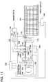
- Fig. 11 is a view of the overall structure of the image recording apparatus of the present invention.
- Fig. 12 is a view of the overall structure of the system which controls the print head from the image processing apparatus of the present invention.
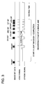
- Fig. 13 is an illustration showing the data signal timing of one step in the present invention.
- Fig. 14 is an illustration of operations showing operating conditions of recording element arrays of the present invention.
- Fig. 15 is an illustration of operations of a signal sending means of a vacuum fluorescent array of the present invention.
- Figs. 16(a) to 16(d) are block diagrams showing a gate circuit for calculation of the present invention.
- Fig. 17 is an illustration of operations of the signal sending means of a 4-division exposure system of the present invention.
- Fig. 18 is an illustration of operations showing a data timing signal control of the 4-division exposure system of the present invention.
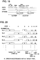
- Fig. 19 is an illustration of operations showing the signal sending means of a 2-division exposure system of the present invention.
- Fig. 20 is an illustration of operations showing the data timing signal control of the 2-division exposure system of the present invention.
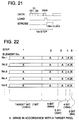
- Fig. 21 is an illustration of operations showing the signal sending means of an undivided exposure system of the present invention.
- Fig. 22 is an illustration of operations showing the data timing signal control of the undivided exposure system of the present invention.
- Fig. 1 is a perspective view of a general structure showing an example of an image recording apparatus of the present invention.
- a sheet of color photographic printing paper P of a silver halide photosensitive material (hereinafter, it will be simply referred to as printing paper) which is controlled by a controlling apparatus 1 for the overall apparatus and fed by rollers, not shown in the drawing, is conveyed while being supported by a supporting drum 2 of a conveyance means which is rotated in the arrowed direction by a driving source, not shown in the drawing; during that time, a red light source recording head 3R, a green light source recording head 3G, and a blue light source recording head 3B in which a plurality of light emitting elements are arranged in an array or a plurality of arrays, are respectively driven and controlled by a line division control section 5 and the control apparatus 1 according to image data; these heads repeat line-shaped dot image exposure for respective colors as described below, and record a color image on the printing paper P.
- a controlling apparatus 1 for the overall apparatus
- the control apparatus 1 compensates for light emitting characteristics of recording heads 3R, 3G and 3B, according to compensation data previously set in a compensation memory 4 in order to compensate for fluctuations of each light emitting element of recording heads 3R, 3G and 3B. Compensation data is stored in a compensation memory as a look-up table, and compensation data corresponding to each emitting element is outputted.
- a line division control section 5 reassembles image data for division exposure, which will be described later, and transfers it to the control apparatus 1 as division exposure data.
- the red light source recording head 3R, green light source recording head 3G and blue light source recording head 3B are array light sources which are mounted opposed to a supporting drum 2 in such a manner that light emitting elements are arranged parallel to a generating line of the supporting drum 2.
- An LED array is used for the red light source recording head 3R.
- vacuum fluorescent print heads (VFPH) are used, in which a zinc oxide fluorescent body (ZnO:Z) having light emitting characteristics in the range of blue - green is used, and which are respectively provided with a green color separation filter and a blue color separation filter.
- the recording pixel density of recording heads is respectively 300 dpi.
- a Selfoc lens array is used as an image forming optical system for each recording head.
- a yellow filter is used as a filter for the green light source, instead of a green filter, because light can be more effectively used when a color photographic printing paper is used.
- a sheet of printing paper P passed through an image exposure station in a position in which recording heads 3R to 3B are parallely arranged, is conveyed to a developing process, not shown in the drawing, by the supporting drum 2, and an output color image can be obtained there by a predetermined development processing.
- Fig. 2 is a block diagram related to a recording head driving control of the control apparatus 1. Referring to Fig. 2, operation control functions of the recording heads 3R to 3B in the control apparatus 1 will be described below.
- each of the recording heads 3R to 3B is operated by the same control, the control of only one recording head will be described. Accordingly, in the drawings other than Fig. 1, that is, in Fig. 2, or Fig. 4 which shows a block diagram to control an image data writing operation of the recording head, Fig. 5 which is a stylized circuit diagram showing an example in which light emitting elements, arrayed in a row, of the recording heads are divided into 3 groups, and in Fig. 6 which is a stylized circuit diagram showing an example in which light emitting elements, arrayed in 3 rows, of the recording heads are divided into 3 groups, the recording heads 3R to 3B are collectively expressed by a recording head 30.
- correction data from a correction memory 4 and image data for division exposure from a line division control section 5 are, initially, read in a multiplication unit 1a, and multiplied, and thereby, image data, in which fluctuation of each light emitting element is corrected for, is sent to an interface 1b.
- a CPU 1c sets an initial counting value to count pixels for 1 line, in a counter 1d through an interface 1b, starts the counter 1d, and controls a demultiplexer 1e for input exchange.
- the counter 1d starts counting and outputs the counted value to the demultiplexer 1e.
- the demultiplexer 1e changes image data of each pixel for every image data for 8 bits x 1 line according to the inputted counted value, and writes it in a line memory 1f and a line memory 1g through the interface 1b.
- image bit data for 1 line in the 1st line is successively outputted from the most significant bit (MSB) of the data to the least significant bit (LSB) of the data, from the line memory 1f to the multiplexer 1h, and is transferred to the recording head 30.
- the output path of image data in the 2nd line is changed from the demultiplexer 1e, and the image data is written in the line memory 1g.
- image bit data means the data composed of only specific bits in the image data.
- image data of the line previously written in one line memory is transferred to the recording head 30, image data of the next line is written in the other line memory, and this is repeated, thereby, image data for each line can be continuously outputted, without being delayed on the basis of time.
- a counter 1i counts the transferring time of the image bit data to the multiplexer 1h under the control of the CPU 1c, and outputs the counted signals to a load signal generating circuit 1j. Due to that, the reset pulse signal generating circuit 1j successively outputs load signals and outputs them to the recording head 30, at the time when image bit data for 1 line has successively been transferred from its MSB to LSB to the recording head 30. In addition to that, it also outputs the load signal to a strobe-signal generating circuit 1m.
- a counter 1k counts strobe-time allotted to each bit of 8 bits of image data, under the control of the CPU 1c, and outputs it to the strobe signal generating circuit 1m. Due to this, the strobe signal generation circuit 1m successively generates strobe signals having strobe time respectively corresponding to each bit of 8 bits of image data from MSB to LSB, and outputs them to the recording head 30 whenever the strobe signal generation circuit 1m receives the load signal from the load signal generating circuit 1j, and also outputs the signal to the CPU 1c. The CPU 1c which received these signals, controls the counter 1i in order to generate the next load signal.
- Fig. 3 is a timing chart of the output signal from the control apparatus 1 to the recording head 30.
- the control apparatus 1 repeats a series of operations described above, the load signal, strobe signal and image data are timed to each other as shown in Fig. 3, and are outputted to the recording head 30.
- MSB is outputted for 1 line as image bit data, and transferred to the recording head 30, and after that, the load signal and the strobe signal are outputted and exposed.
- a period of time during which the strobe signal exists that is, exposure time is 40 ms, which is previously allotted to the MSB.
- the period of the strobe signal is 20 ms, and hereinafter, in the same manner , 10.2 ms for the third bit, 5.4 ms for the 4th bit, 3 ms for the 5 th bit, 1.8 ms for the 6 th bit, 1.2 ms for the 7 th bit, and 0.9 ms for the LSB.
- fluctuations of an amount of emitting light of each light emitting element of the recording head 30 are corrected by a method of multiplication of correction data and image data, however, the present invention is not limited to that, and the fluctuations may be corrected by an addition method, including a minus addition.
- an example is shown in which bit-processing is carried out in the order from the MSB to the LSB, however, this order of bits is not limited to the above, and for example, the order from the LSB to MSB, or other orders, may be adopted.
- each recording head will be described in an example in which recording elements are arranged in one row as shown in Fig. 10 (a).
- the control will be described according to an example of image data for one color.
- recording elements in the array-like arrangement direction are successively numbered in order, from the end of the recording elements, and classified into N groups, that is, a group of elements G 1 , in which the remainder is 1 in the remainder system of the number N; a group of elements G 2 , having a remainder of 2; ⁇ , a group of elements G N-1 , having a remainder of N-1; and a group of elements GN, having a remainder of 0.
- the N division exposure means a exposure method in which exposure time periods of the above N groups do not overlap each other in the exposure of the lines in the array-like arrangement direction.
- Fig. 5 and Fig. 10(a) show an example of a 3 division exposure.
- the control system is set so that the array emits practically no light.
- a line division control section 5 transfers image data to the control apparatus 1 as division exposure image data in which pixels, except the pixels corresponding to the group G 1 in image data of 1 line, are set to 0.
- the control apparatus 1 controls the exposure time corresponding to the transferred image data and exposure is carried out. As a result, the image is exposed in only pixels corresponding to the group G 1 .
- the line division control section 5 transfers image data to the control apparatus 1 as division exposure image data in which pixels, except the pixels corresponding to the group G 2 in image data of 1 line are set to 0.
- the control apparatus 1 controls the exposure time corresponding to the transferred image data, and exposure is carried out. As a result, the image is exposed in only pixels corresponding to the group G 2 .
- recording elements of the group G a (a is an integer of 1 through N) are active, recording elements of the group, except the group G a , are set to be inactive.
- an image can be recorded on a predetermined area on the printing paper.
- the recording elements are arranged zigzag in a plurality of rows as shown in Fig. 6 and Fig. 10 (b), or also in the case where one row or zigzag arrangements are arranged in a plurality of rows
- the line division control section 5 controls in the same manner after a combination of line data has been appropriately changed, the same effects can be attained if the image is recorded by the N division exposure.
- the arrangement pitch and row pitch of zigzag arrangement of the recording element 4 are equal to the pixel pitch of 300 dpi in Fig.
- a combination of data is previously changed as follows, such as, the first pixel in the N-th line, the second pixel in the (N + 1)th line, the third pixel in the (N + 2)th line, the fourth pixel in the N-th line, the fifth pixel in the (N + 1)th line, the sixth pixel in the (N + 2)th line, the seventh pixel in the N-th line, ⁇ , and data for new one line is formed.
- the N-division exposure control may be conducted on this new one line data.
- the present invention is not limited to this.
- the N-division exposure control is a simple exposure control method in which the exposure control section becomes rather simple, and in which it is possible that the exposure time period of the recording elements, adjoining in the arrangement direction of the array, do not overlap each other, which is preferable.
- the present invention is not limited to this method, but the following method may also be applied: for example, as shown in Figs. 5 and 6, the wiring structure is divided for each group in the array light source itself; and exposure for each group is controlled by switch circuits S1 and S2, conceptually shown in the drawing, or similar devices.
- the exposure control method structured such that the exposure time periods of recording elements adjoining in the arrangement direction of the array do not overlap each other, is not limited to the N-division exposure method.
- an exposure control may be accepted in which the exposure time periods of recording elements adjoining in the arrangement direction of the array do not overlap each other.
- a recording head is respectively adopted in which a green filter and a blue filter for color separation are respectively combined with a VFPH, which is composed of a combination of a vacuum fluorescent tube array having light emitting characteristics in the blue - green range, with a Selfoc lens array as an image forming optical system.
- a combination of a VFPH and a red filter may be used for the red light source recording head 3R, and a combination of an LED array and a Selfoc lens array may be used for the green light source recording head 3G and the blue light source recording head 3B.
- a light emitting body + a shutter array (a liquid crystal shutter array, PLZT shutter array, or the like), a laser array in which lasers are arranged, (an LD laser array, or the like) may be appropriately combined and used.
- an image forming optical system it is not limited to the Selfoc lens, but a roof mirror lens array, or similar lenses, may also be used.
- a recording head may be used for only one color for monochromatic image recording.
- the ratio of an anode voltage to a grid voltage is controlled within a range lower than 0.9, the interaction between recording elements becomes small at the time of light emission, thereby, the effect of improvement of "step up/down" in gradation according to the present invention is greater, and when the ratio of voltage is more than 0.3, the amount of light is not insufficient, and accordingly, it is most preferable that the ratio is higher than 0.3 and lower than 0.9.
- the strobe signal is set corresponding to the weight of each digit when image data is expressed by binary, using a light source controlled by the binary control of ON and OFF, or alternately, a light source, controlled by multi-value control, is used, and the strobe signal may be set corresponding to the controlled light source.
- a light source which can change not only light emitting time but also light emission brightness, is used as a light source controlled by a multi-value control, and thus an appropriate strobe signal may be set.
- image data having any number of bits, such as 10 bits or 12 bits, may be used, and an appropriate strobe signal may be set.
- the photosensitive material a photosensitive material for monochromatic photography, or cut paper sheets may be used. Still further, effects of the invention can be attained by also using the following material: as silver halide photosensitive materials, printing paper composed of a transparent or translucent supporting body, negative film, reversal film, positive paper, instantaneous photosensitive material having self processing solution, a color material transfer system thermal development photosensitive material, or the like; and for the material other than silver halide photosensitive material, thimal color film, electrophotographic system photosensitive material, or similar materials.
- the same effects can also be attained in the recording system using other than light, such as a thermal system in which a thermal head is used as the recording head; the transferred amount of the color material is controlled by heat, or coloring in a micro-capsule included in the recording paper is controlled, or the like.
- the printing paper P is not limited to color photographic paper, but monochromatic photographic paper may also be used. Specifically, when a colored silver halide photosensitive material is used, a large problem occurs in which there is a difference between sharpness in the direction of array, and that in the direction perpendicular to the array. Accordingly, the effect of improvement by the present invention is large, which is preferable. Further, the printing paper P is not limited to a roll-like printing paper, but may be a cut-printing paper.
- the effect of the improvement of "step up/down” in gradation according to the present invention is greater, which is preferable. More specifically, in the case of color silver halide photosensitive material, the effect of the improvement of "step up/down” in gradation according to the present invention is much greater, which is more preferable. Furthermore specifically, in a so-called silver chloride photosensitive material, which has a silver halide emulsion layer more than the silver chloride including ratio of 90 mol % in the color silver halide photosensitive material, the effect of the improvement of "step up/down” in gradation according to the present invention is greater, which is still more preferable.
- the effect of improvement of "step up/down" in gradation according to the present invention is greater, which is more preferable.
- silver chloride paper which has a silver halide emulsion layer having a silver chloride including ratio of more than 90 % in a color silver halide photosensitive material, and has a reflection supporting body, the effect of improvement according to the present invention is largest, which is most preferable.
- a recording medium conveyance means for a printing paper sheet P, or the like is not limited to the supporting drum 2 shown in Fig. 1, but may be a system in which the recording medium is conveyed on the plane, a printing paper sheet is fixed and the recording head is moved, or a recording paper sheet P and the recording head 30 are moved together.
- the shape of the recording medium is not limited to the roll-shape, but may be sheet-shaped, or in the shape of a photoreceptor drum, and a conveyance means corresponding to their shape may be used.
- an array recording head is used in which a red light emitting LED array in which the pixel density of one row is 300 dpi, and a Selfoc lens array are combined; and the 2 division exposure control is carried out.
- an array recording head in which a green filter and a blue filter for color separation are respectively combined with a VFPH, composed in combination of a vacuum fluorescent tube array in which the recording density of one row is 300 dpi, with a Selfoc lens array, is used without the division exposure control.
- a printing paper sheet P which is a color silver halide photosensitive material composed of a silver halide emulsion layer having a silver chloride including ratio of more than 90 mol %, is pulse-conveyed at the average speed of 30 mm/sec by the supporting drum 2.
- a close-up image of a subject has been printed on the printing paper P at the exposure time interval for a line-like dotted image, in which the image density in the conveyance direction is made almost equal to that in the direction of the recording element array, a recording image is obtained by development processing.
- the VFPH driving voltage is made to be 40 V for both the anode and the grid.
- a recording image is obtained in the same manner as in Example 1-1, except that the division exposure control is not carried out on the red light source recording head 3R, and the 2 division exposure control is carried out on the green light source recording head 3G.
- a recording image is obtained in the same manner as in Example 1-1, except that the division exposure control is not carried out on the red light source recording head 3R, and the 2 division exposure control is carried out on the blue light source recording head 3G.
- a recording image is obtained in the same manner as in Example 1-1, except that a 2 division exposure control is carried out on the green light source recording head 3G, and also on the blue light recording head 3B.
- a recording image is obtained in the same manner as in Example 1-1, except that a 3 division exposure control is carried out on each of the red light source recording head 3R, green light source recording head 3G and blue light source recording head 3B.
- a recording image is obtained in the same manner as in Example 1-1, except that a 4 division exposure control is carried out on each of the red light source recording head 3R, green light source recording head 3G and blue light source recording head 3B.
- a recording image is obtained in the same manner as in Example 1-1, except that a 6 division exposure control is carried out on each of the red light source recording head 3R, green light source recording head 3G and blue light source recording head 3B.
- a recording image is obtained in the same manner as in Example 1-1, except that the division exposure control is not carried out on the red light source recording head 3R.
- a recording image is obtained in the same manner as in Example 1-4, except that the pixel density of one row is 150 dpi for each of the red light source recording head 3R, the green light source recording head 3G and the blue light source recording head 3G.
- a recording image is obtained in the same manner as in Example 1-4, except that the pixel density of one row is 200 dpi for each of the red light source recording head 3R, the green light source recording head 3G and the blue light source recording head 3G.
- a recording image is obtained in the same manner as in Example 1-4, except that the pixel density of one row is 400 dpi for each of the red light source recording head 3R, the green light source recording head 3G and the blue light source recording head 3G.
- a recording image is obtained in the same manner as in Comparative Example 1-1, except that the pixel density of one row is 150 dpi for each of the red light source recording head 3R, the green light source recording head 3G and the blue light source recording head 3G.
- a recording image is obtained in the same manner as in Comparative Example 1-1, except that the pixel density of one row is 200 dpi for each of the red light source recording head 3R, the green light source recording head 3G and the blue light source recording head 3G.
- a recording image is obtained in the same manner as in Comparative Example 1-1, except that the pixel density of one row is 400 dpi for each of the red light source recording head 3R, the green light source recording head 3G and the blue light source recording head 3G.
- a recording image is obtained in the same manner as in Example 1-4, except that a 3 division exposure control is carried out on the green light source recording head 3G.
- a recording image is obtained in the same manner as in Example 1-4, except that a 4 division exposure control is carried out on the green light source recording had 3G.
- a recording image is obtained in the same manner as in Example 1-4, except that a 6 division exposure control is carried out on the green light source recording had 3G.
- a recording image is obtained in the same manner as in Example 1, except that a monochromatic silver halide photosensitive material, having color sensitivity to red, is exposed by carrying out the 2 division exposure control on the red light source recording head 3R; the other 2 color heads 3G and 3B are not emitted; and development processing for the monochromatic photosensitive material is carried out after exposing.
- a monochromatic image is used in the same scene as in Example 1-1.
- a recording image is obtained in the same manner as in Example 1-14, except that the division exposure control is not carried out on the red light source recording head 3R.
- a recording image is obtained in the same manner as in Example 1-4, except that the anode voltage of the green light source recording head 3G is 36 V.
- a recording image is obtained in the same manner as in Example 1-4, except that the anode voltage of the green light source recording head 3G is 25 V.
- a recording image is obtained in the same manner as in Example 1-4, except that the anode voltage of the green light source recording head 3G is 12 V.
- a recording image is obtained in the same manner as in Example 1-4, except that the anode voltage of the green light source recording head 3G is 8 V.
- Example Comparative Example 1-1 1-4 1-5 1-6 1-7 No. of divisions of division exposure control of the recording head 3R 2 3 4 6 1 3G 2 3 4 6 1 3B 2 3 4 6 1 Review G GG GGG GGG N G: good N: no good
- Example Comparative Example 1-8 1-9 1-4 1-10 1-2 1-3 1-1 1-4 No. of divisions of division exposure control of the recording head 3R 2 2 2 2 1 1 1 1 3G 2 2 2 2 1 1 1 1 3B 2 2 2 2 1 1 1 1 1 1 Density of pixel (dpi) 150 200 300 400 150 200 300 400 Review G G G N NN NN NN G: good N: no good
- Example 1-4 1-15 1-16 1-17 1-18 VFPH driving voltage of 3G (V) anode 40 36 25 12 8 grid 40 40 40 40 40 Voltage ratio anode/grid 1.0 0.9 0.6 0.3 0.2 Amount of light GGG GGG GGG GG G Continuity of gradation G GG GGG GGG GGG G: good N: no good
- a recording image is obtained in the same manner as in Example 1, except that fluctuations for each recording element are compensated for in the red light source recording head 3R, by the following procedures.
- Example 1-19 and Comparative Example 1-6 are reviewed in the same manner as in Example 1-1. As a result, Example 1-19 has a density unevenness smaller than Comparative Example 1-6, and also has no "step up/down" in gradation. Thus, a high quality image having excellent gradation continuity can be obtained.
- the recording image is obtained in the same manner as in later Example 1-21, except that the compensation is carried out by the following processes.
- a recording image is obtained in the same manner as in Example 1-19, except that the compensation is carried out by the following processes.
- Example 1-20 and 1-21 there is no gradation in the same manner as in Example 1-19. Further, in Example 1-20, an excellent image can be obtained in which uneven density is less than in Example 1-19. Further, in Example 1-21, an excellent image can be obtained, in which uneven density is less than in Example 1-20, and in which uneven density is less specifically in fine pitches.
- Examples 1-20 and 1-21 Konica Micro-Densitometer PDM-5 Type BR made by Konica Corporation, is used as a density measurement device.
- Konica Micro-Densitometer PDM-5 Type BR made by Konica Corporation.
- scanners such as a commercial flat bed scanner, or a drum scanner, almost equal effects can be obtained.
- Examples 1-20 and 1-21 an average value of all recording elements is used as the reference addition density (D 0 ), and the reference amount of light (P 0 ). However, when the same review is conducted by using the maximum value or minimum value in all recording elements as the reference, approximately equal effects can be obtained.
- a sheet of printing paper (a paper for silver halide photographic photosensitive material) is used for a compensation image and a review image.
- a silver halide photosensitive material a transparent or translucent printing paper
- a photosensitive material on which a visible image can be formed such as a negative film, a reversal film, a reversal paper, a photosensitive material sensitive to wavelength of visible - infrared light, a monochromatic photosensitive material, a photosensitive material having self processing solution (an instantaneously usable photosensitive material), or similar materials, which is a photosensitive material capable for forming a visible image, may be used, and when an exposure device to expose them using a light source having an appropriate wavelength is used, the same effects can be attained.
- a photosensitive material for a compensation image may be different from a photosensitive material used for actual image formation, however, it is preferable that the same photosensitive material is used for the reason that compensation can be carried out including characteristics of the photosensitive material, or similar reasons.
- the accuracy of compensation can also be increased when a compensation image is outputted by carrying out compensation using a compensation value obtained as necessary; and an operation for obtaining a compensation value is further repeated in the same manner.
- a sensor which has a measuring area and a measuring range sufficient to measure the brightness of the 2 recording elements without decreasing the brightness.
- red light source recording head 3R a recording image is obtained in the same manner as in Example 1-19, except that compensation is carried out in the following steps.
- a sensor which has a measuring area and a measuring range sufficient to measure the brightness of 4 recording elements without decreasing the brightness.
- Fig. 8 shows an example of the changing ratio of the light amount according to the example of this experiment.
- Examples 1-22 and 1-23 show no "step up/down" in gradation, which is the same as Example 1-19. Further, in Example 1-22, an excellent image is obtained in which the density unevenness is less than in Example 1-19, and specifically, large unevenness is less on the whole. Still further, in Example 1-23, an excellent image can be obtained in which the density unevenness is still less than Example 1-22, and specifically, the unevenness is less in the fine pitch.
- each recording element has been measured while one sensor is being moved along the array, the same effect can also be attained by using a plurality of sensors. Further, when a sensor array, such as a linear CCD, is used and measurement is carried out without moving the sensor, almost the same effect can be attained.
- Example 1-22 an example of simultaneous emission of the 2 recording elements has been shown, however, the number of measurements is not limited to this example. That is, when a plurality of recording elements simultaneously emit light, almost the same effects can be attained by obtaining the brightness (E i ) of each recording element by using an appropriate calculation operation.
- Calculation methods are not limited to those in Examples 1-22 and 1-23, and when a method is used in which the brightness of one recording element can be roughly calculated by an appropriate calculation processing corresponding to characteristics of the used array light source, under the condition of simultaneous emission of a plurality of recording elements, almost the same effects can be attained.
- an appropriate function may be used corresponding to characteristics of a used array light source.
- Example 1-24 an excellent image can be obtained in Example 1-24, in which there is no "step up/down" in gradation as in Example 1-19; the large unevenness on the whole and unevenness in fine pitch are less than in Example 1-19; and density unevenness is still less.
- Example 1-24 Although light is shielded using an aperture in Example 1-24, almost the same effects can also be attained when a measuring method, which is not affected by light from other recording elements, is used, for example, when a sensor itself having high directivity in the direction of irradiation of light from the recording element is used; light is collected by a lens; or only light from the specific recording element is conducted by using an optical fiber.
- a VFPH in which the red light source recording head 3R, green light source recording head 3G and blue light source recording head 3B are arranged, is respectively compensated for by using the method described in Example 1-20.
- an image is outputted in the same manner as in Example 1-6 except that, a high quality image which has no "step up/down" in gradation and less unevenness, can be obtained.
- Examples 1-19 to 1-25 examples of compensation by only density measurement or brightness measurement have been described, however, compensation may be carried out in a combination of both of them.
- the density measurement means or the brightness measurement means may be mounted in the image forming apparatus, or compensation data may be calculated outside the apparatus without mounting these means, and then stored in the memory.
- Examples 1-19 to 1-25 a means has been used by which compensation data is obtained by using the array light source itself to be compensated. However, even when compensation data is obtained by using the same kind of array light source, and the same kind of array light source which is different from the array light source by which the compensation data has been obtained, is compensated for by using the obtained compensation data, the same effects can also be attained.
- the same kind of array light source described here shows an array light source in which characteristics of light emission is approximately similar to each other when a plurality of recording elements emit the light.
- formed image 1 in which a solid image is formed which has a uniform density in a predetermined area, and has a stepped-density, in which a time period from the minimum exposure time to the maximum exposure time is divided into several steps of time
- a formed image 2 in which an image, including a close-up of a face of the subject with a gray gradation background, is formed
- the maximum number of times of light emission in the plural number of times of exposure that is, the number of gradations is shown by the number of bits in Table 7, and the time period of the strobe signal is appropriately adjusted and unified.
- an image forming apparatus can be provided which can form a high quality image having excellent gradation continuity, little density unevenness, and acceptable maximum density, without increasing the complexity of the apparatus nor increasing the cost.
- the number of gradations is less than 65536, the time period required for processing and the required memory capacity are reduced to almost 2/3, compared to cases in which the number of gradations is more than 65536, and the necessary circuit can be simplified, resulting in an acceptable apparatus.
- the multi-valued recording element in the example represents the following.
- a 16-valued recording element which represents a light source in which each recording element is controlled by the gradation control and the light emission time control at 16 levels (which correspond to levels expressed by 4 bits on the binary recording element).
- an image forming apparatus when the number of gradations is more than 512, an image forming apparatus can be provided, which can form a high quality image having an excellent gradation continuity, little density unevenness, and an acceptable maximum density, without increasing the complexity of the apparatus nor increasing the cost.
- the number of gradations is less than 65536, a time period required for processing and the necessary memory capacity are reduced to almost 2/3, compared to the case in which the number of gradations is more than 65536, and the necessary circuit can be simplified, resulting in an acceptable apparatus.
- the recording element in which light emission time can be controlled was used as the multi-valued recording element in Example 1-27, however, when the multi-valued recording element in which light emission intensity can be controlled is used, an appropriate strobe signal is set, so that the image can be formed.
- an image recording apparatus using array type recording heads can be structured so as to be simply and effectively controlled in such a manner that, at least, exposure time of recording elements adjoining in the arrangement direction of the array does not overlap any other exposure time.
- an image forming apparatus can be realized, in which there is no possibility that the exposure control section is greatly complicated; the exposure light amount becomes insufficient; the "step up/down" in gradation is discontinuously generated; and in which a continuous gradation image, having little density unevenness and high quality, can be recorded, and processing speed is also increased. Accordingly, a simple, small size and low cost apparatus can be realized.
- red light source recording head 3R a combination of a red light emitting LED array in which the pixel density of one row is 300 dpi, and a Selfoc lens array are used; and a double division exposure control is carried out.
- an array recording head in which a green filter and a blue filter for color separation are respectively combined with a VFPH, composed in combination of a vacuum fluorescent tube array in which the recording density of one row is 300 dpi, and a Selfoc lens array, is used without the division exposure control.
- a sheet of printing paper P which is a color silver halide photosensitive material composed of a silver halide emulsion layer having a silver chloride including ratio of more than 90 mol %, is conveyed at a speed of 30 mm/sec by the supporting drum 2.
- a natural image, including letters has been printed on the printing paper P at the exposure time interval for a line-like dotted image, in which the pixel density in the conveyance direction is made almost equal to that in the direction of the recording element array, in two ways of a vertical direction, in which the vertical direction of the image is equal to the conveyance direction of the printing paper P, and a horizontal direction in which the same image is previously rotated by 90°, a vertical recording image and a horizontal recording image are obtained by development processing.
- the vertical image and the horizontal image are obtained in the same manner as in Example 1, except that the red light source recording head 3R is not division exposure-controlled.
- Example 2-1 Comparative Example 2-1 No. of divisions of division exposure control of the recording head 3R 2 1 3G 1 1 3B 1 1 Review 1 G N 2 G N G: good N: no good
- Example 2-1 additional test like Example 2-1 conducted for Example 1-1 was also conducted and examined for Examples 1-2 to 1-14 and Comparative Examples 1-2 to 1-4 so as to obtain the vertical image and the horizontal image.
- test results similar to afore-mentioned test results in Tables 1 to 4 were also obtained for Reviews 1 and 2.
- a vertical image and a horizontal image are obtained in the same manner as in Comparative Example 2-1, except that the printing paper P of monochromatic silver halide photosensitive material is used, and exposure is carried out by using only a red light source recording head 3R.
- a vertical image and a horizontal image are obtained by the exposure control in the same manner as in Example 1-4, except that the printing paper P of colored silver halide photosensitive material composed of a silver halide emulsion layer having a silver chloride including ratio of 50 mol% is used.
- a vertical image and a horizontal image are obtained in the same manner as in Comparative Example 2-1, except that the printing paper P of colored silver halide photosensitive material composed of a silver halide emulsion layer having a silver chloride including ratio of 50 mol% is used.
- a vertical image and a horizontal image are obtained by the exposure control in the same manner as in Example 1-4, except that silver halide photosensitive material is used in which a transparent supporting body is used instead of a reflective supporting body of the printing paper P in Example 2-1.
- a vertical image and a horizontal image are obtained in the same manner as in Comparative Example 2-1, except that the silver halide photosensitive material similar to that in Example 2-16 is used.
- Fig. 9 in the printing operation onto the recording paper P, when at least only one of the red light source recording head 3R, the green light source recording head 3G or the blue light source recording head 3B is division exposure-controlled, such that a pixel is not recorded by simultaneous light emission of the recording element adjoining in the arrangement direction of the array, then, an excellent color image can be recorded in which the difference of sharpness is less than that in the case where all recording heads are not division exposure-controlled. Further, also in the case where a monochromatic image is recorded, an excellent monochromatic image in which the difference of sharpness is less, can be recorded when the recording head is division exposure-controlled. Still further, it can be seen from Table 9 that, when a color image is recorded, the division exposure control of the green light source recording head 3G is more effective than that of other color light source recording heads.
- a pixel which is recorded by a recording head arranged array-like is not formed, at least, by simultaneous light emission of a recording head adjoining in the arrangement direction of the array, and therefore, an excellent image, which has no difference of sharpness in the direction of the array nor in the direction perpendicular to that direction, can be recorded on the silver halide photosensitive material. Further, in the case where a silver halide material is a color silver halide photosensitive material, the above effects are greater.
- a color silver halide photosensitive material having a silver halide emulsion layer in which a silver chloride including ratio is more than 90 %, is used as a silver halide photosensitive material, a more excellent image than in a conventional image recording apparatus, can be formed.
- the apparatus can be simply structured without making the control section complicated, and cost is subsequently lowered.
- the effect of improvement for the difference of the sharpness is further increased.
- the density of pixels is more than 200 dpi, the above effect is still greater, which is larger than in cases in which a silver halide photosensitive material having a reflective supporting member is used.
- Fig. 11 shows an overall structure of image recording apparatus 1 of the invention.
- Image data are first inputted from the outside into an image data interface and data processing circuit 140 where the image data are subjected to image processing such as gradation change and sharpness correction based on the control of system control circuit 180, and then are sent to control circuits 121, 122 and 123 each being for each print head.
- control circuits 121, 122 and 123 for each print head sends control signals control signals, after being subjected to intensity correction between elements, to each of print heads 108, 108A and 108B provided with recording elements in a form of an array in one row or in plural rows, thus, the print heads 108, 108A and 108B are driven.
- Print head 108 is a gallium arsenide phosphide light emitting diode print head having its center wavelength at 660 nm.
- Print head 108A is a zinc sulfide vacuum fluorescent tube print head having its center wavelength at 505 nm
- print head 108B is a zinc sulfide vacuum fluorescent tube print head having its center wavelength at 505 nm,
- the print 108 conducts exposure for red
- print head 108A is equipped with yellow gelatin filter 132, and conducts exposure for green
- print head 108B is equipped with blue gelatin filter 133, and conducts exposure for blue.
- precision transport roller and pulse motor unit 151 and paper supply adjusting mechanisms 152 and 163 are operated by the control of transport roller control circuit 150 based similarly on the control of system control circuit 180, and thereby, light-sensitive paper 201 is transported from paper supply magazine 200 at high speed in the arrowed transport direction shown in Fig. 11.
- paper guide position control mechanism 90 causes paper guides 191, 192 and 193 to be operated so that the light-sensitive paper 201 is controlled to be at the image forming position of an optical system of print heads 108, 108A and 108B, then, is transported precisely in the direction opposite to the arrowed transport direction in Fig. 11 by the precision transport roller and pulse motor unit 151, and thus, the exposed portions are accumulated in the paper supply adjusting mechanism 152.
- this precision transport exposures for three colors are conducted simultaneously by the print heads 108, 108A and 108B.
- the light-sensitive paper 201 is transported at high speed again in the arrowed transport direction shown in Fig. 11, and the exposed portion of the light-sensitive paper 201 is cut when it is at its prescribed position through operation of paper cutting unit 170.
- the exposed light-sensitive paper 201 which has been cut is transported to processing apparatus 161 wherein temperature and transport are controlled by processing apparatus control circuit 160, and it passes through a developing tank, a fixing tank, a first stabilizing tank, a second atablilizing tank, a third stabilizing tank and a drying section successively to be processed, and is ejected out of a print outlet.
- Image data processed by an image data interface and a data processing circuit are inputted in print head control circuit 121 (,122 and 123) through image data transport section 103.
- Signals outputted from the print head control circuit 121 (,122 and 123) are inputted in the print heads 108 (,108A and 108B) as image data.
- data signals and clock signals which are image data are inputted from the print head control circuit 121 into shift register 109 in the print head 108 through signal transport section 105, load pulse signals are inputted from the print head control circuit 121 into latch circuit 110 through signal transport section 106, and strobe signals are inputted from the print head control circuit 121 into gate 111 through signal transport section 107.
- the print head 108 structured in aforesaid manner transmits signals to the shift register 109, latch circuit 110 and gate 111 in this order to operate recording element array 113 through driving circuit 112. (Same operations are conducted also for print head control circuits 122 and 123.)
- Fig. 13 shows data signal timing in one step of each of aforesaid clock signals, data signals, load pulse signals and strobe signals which are outputted from the print head control circuit 121.
- contents of No. 1, No. 2, No. 3 and No. 4, ... No. N of data signals are stored in the shift register 109.
- all contents in the shift register 109 are stored temporarily in latch circuit 110.
- the strobe signals are on the process of operation (driving time)
- an element in recording element array 113 with which the contents of the latch circuit 110 correspond to No. 1 among No. 1 - No. N of the latch circuit 110 is driven selectively by driving circuit 112.
- Fig. 14 shows how the emitting timing in the occasion where aforesaid recording element array 113 is a light emitting element such as, for example, an LED array element is controlled by data signal timing shown in Fig. 13.
- Light-emitting element numbers such as element No. 1, element No. 2, element No. 3, ... are represented by the axis of ordinates, and steps 1, 2, 3, 4, ... are represented by the axis of abscissas (time axis direction). Steps 1, 2, 3, 4, ... of each element number are indicated by 4 types of driving modes.
- Table 10 below shows, in accordance with the number of data, driving or non-driving for 4 types of driving modes shown in Fig. 16.
- the symbol U represents driving
- V represents non-driving
- W represents the driving which is performed depending on contents of an objective bit.
- a closest driving element distance is 4, and when a density level in the vicinity area is smaller than boundary data 128 of density signal area, a closest driving element distance is 2.
- the closest driving element distance is a distance between two elements which are emitting simultaneously. For example, when adjoining two driving elements are not driving and an element adjoining the two driving elements is driving, the distance is 3.
- the boundary data of a density signal area is a minimum signal value of each density signal area when a total range for all density signal values is divided into plural density signal areas as shown in Table 10.
- Aforesaid vicinity area is an area including at least several closest driving element distances, and it is a local area when viewed from the overall image, and in general, it is an area where density levels are comparatively uniform.
- the vicinity area assumed is represented by 10 - 20 pixels, or by an area of 1 - 2 mm or less, when conducting recording of 300 - 400 dpi with a total image of about A4 size.
- the objective bit is the 3rd bit, and this drives with emitting time of one step which is 8 m clock (total, 8 m x 4).
- an unillustrated objective bit is the 2nd bit, and this drives with emitting time of one step which is 4 m clock (total, 4 m x 4).
- 4 steps of each objective bit are subjected to emitting at the total of 24 steps while moving the objective bit to the 0-th bit (LSB: least significant bit), and after that, recording for one line is completed after a proper non-emitting time for adjustment of quantity of light.
- the n-th bit corresponds to a value of a digit having weight of 2 n among 8-bit image data.
- a vacuum fluorescent tube array is used as a recording element array
- a color photographic paper (negative paper) employing silver chloride grains is used as a light-sensitive material which is a recording medium.
- Aforesaid bit-division multi-exposure system is used basically as a gradation presentation system.
- D1280, D1281, D1282, ..., up to D1919 are transmitted, and a load pulse is generated once, and then, strobe signal becomes active for 32 m clock after load pulse completion, in the same way as in the foregoing.
- D1920, D1921, D1922, ..., up to D2559 are transmitted, and a load pulse is generated once, and then, strobe signal including also data signals become active for 32 m clock after load pulse completion, in the same way as in the foregoing.
- the illustration has been explained above, and operations are continued to the fifth step and to the sixth step.
- Aforesaid AND operation and OR operation are conducted by gate circuits shown in Figs. 16 (a), 16 (b), 16 (c) and 16 (d).
- OR operation of y a
- c is conducted in Fig. 16 (b)
- OR operation and AND operation for y a & (b
- c) are conducted in Fig. 16 (c)
- AND operation and OR operation for y a
- (b & c) are conducted in Fig. 16 (d).
- Aforesaid signal transmission is repeated for D-n[4] in place of D-n[5].
- strobe signal is 16 m clock respectively.
- the signal transmission is further repeated for D-n[3] in place of D-n[5].
- strobe signal is 8 m clock respectively.
- the signal transmission is further repeated for D-n[2] in place of D-n[5].
- strobe signal is 4 m clock respectively.
- the signal transmission is further repeated for D-n[1] in place of D-n[5].
- strobe signal is 2 m clock respectively.
- the signal transmission is further repeated for D-n[0] in place of D-n[5].
- strobe signal is m clock respectively.
- 1 clock is used for transmission of data signals and load signals, and overlapping in terms of time of data signal transmission and strobe signal transmission is prevented.
- Table 11 shows data, exposure time and closest light-emitting element distance.
- Table 11 Data Exposure time (clock number) Closest light-emitting element distance 0 ⁇ d ⁇ 64 d ⁇ m 4 64 ⁇ d ⁇ 128 (d-1) ⁇ m 2 128 ⁇ d ⁇ 192 (d-2) ⁇ m 1 192 ⁇ d ⁇ 256 (d-3) ⁇ m 1
- D1280, D1281, D1282, ..., up to D1919 are transmitted, and a load pulse is generated once, and then, strobe signal becomes active for 128 m clock after load pulse completion, in the same way as in the foregoing.
- D1920, D1921, D1922, ..., up to D2559 are transmitted, and a load pulse is generated once, and then, strobe signal becomes active for 128 m clock after load pulse completion, in the same way as in the foregoing.
- the illustration has been explained above, and operations are continued to the fifth step and to the sixth step.
- Aforesaid signal transmission is repeated for D-n[6] in place of D-n[7].
- strobe signal is 64 m clock respectively.
- the signal transmission is further repeated for D-n[5] in place of D-n[7].
- strobe signal is 32 m clock respectively.
- strobe signal is 16 m clock respectively. (for the 13th - 16th steps)
- the signal transmission is further repeated for D-n[3] in place of D-n[7].
- strobe signal is 8 m clock respectively.
- the signal transmission is further repeated for D-n[2] in place of D-n[7].
- strobe signal is 4 m clock respectively. (for the 21st - 24th steps)
- the signal transmission is further repeated for D-n[1] in place of D-n[7].
- strobe signal is 2 m clock respectively. (for the 25th - 28th steps)
- the signal transmission is further repeated for D-n[0] in place of D-n[7].
- strobe signal is m clock respectively. (for the 29th - 32nd steps)
- Fig. 19 shows how the emitting timing in Example 3-2 in the occasion where aforesaid recording element array 113 is a light emitting element such as, for example, an LED array is controlled by data signal timing shown in Fig. 2.
- element No. 1, element No. 2, element No. 3, ... are represented by the axis of ordinates
- steps 1, 2, 3, 4, ... are represented by the axis of abscissas (time axis direction).
- “A” represents light-emitting timing for turning on or off in accordance with objective bit at positions of steps 1, 2, 3, 4, ... each corresponding to each element number.
- steps 1 - 4 For example, in a range of objective 7 bits (steps 1 - 4), if the objective bit is 1 at the step 1 in element No. 1, the driving is conducted with "A”, if the objective bit is 1 at the step 3 in element No. 2, the driving is conducted with "A”, and if the objective bit is 1 at the step 2 in element No. 3, the driving is conducted with "A”. Further, with regard to 6 objective bits, if each objective bit is 1 at steps 5 - 8, this shows that the driving is conducted with "A”. Further, with regard to 5 objective bits, it is shown that the driving is conducted with "A" respectively at steps 9 - 12.
- strobe signal is 64 m clock respectively.
- the signal transmission is further repeated for D-n[5] in place of D-n[7].
- strobe signal is 32 m clock respectively. (for the 5th and 6th steps)
- the signal transmission is further repeated for D-n[4] in place of D-n[7].
- strobe signal is 16 m clock respectively. (for the 7th and 8th steps)
- the signal transmission is further repeated for D-n[3] in place of D-n[7].
- strobe signal is 8 m clock respectively. (for the 10th and 11th steps)
- the signal transmission is further repeated for D-n[2] in place of D-n[7].
- strobe signal is 4 m clock respectively. (for the 11th and 12th steps)
- the signal transmission is further repeated for D-n[1] in place of D-n[7].
- strobe signal is 2 m clock respectively.
- the signal transmission is further repeated for D-n[0] in place of D-n[7].
- strobe signal is m clock respectively. (for the 15th and 16th steps)
- Fig. 20 shows how the emitting timing in the occasion where aforesaid recording element array 113 in Example 3-3 is a light emitting element such as, for example, an LED array is controlled by data signal timing shown in Fig. 13.
- element No. 1, element No. 2, element No. 3, ... are represented by the axis of ordinates
- steps 1, 2, 3, 4, ... are represented by the axis of abscissas (time axis direction).
- “A” represents light-emitting timing for turning on or off in accordance with objective bit at positions of steps 1, 2, 3, 4, ... each corresponding to each element number.
- steps 1 - 2 For example, in a range of objective 7 bits (steps 1 - 2), if the objective bit is 1 at the step 1 in element No. 1 and at the step 2 in element No. 2, the driving is conducted with "A”, and if the objective bit is 1 at the step 1 in element No. 3, the driving is conducted with "A”. Further, with regard to 6 objective bits and 5 objective bits, if each objective bit is 1 at steps 3 and 4 and at steps 5 and 6 respectively, this shows that the driving is conducted with "A", and with regard to 4 objective bits, it is shown that the driving is conducted with "A” respectively at steps 7 and 8.
- the signal transmission is further repeated for D-n[5] in place of D-n[7].
- strobe signal is 32 m clock respectively.
- the signal transmission is further repeated for D-n[4] in place of D-n[7].
- strobe signal is 16 m clock respectively.
- the signal transmission is further repeated for D-n[3] in place of D-n[7].
- strobe signal is 8 m clock respectively.
- the signal transmission is further repeated for D-n[2] in place of D-n[7].
- strobe signal is 4 m clock respectively.
- the signal transmission is further repeated for D-n[1] in place of D-n[7].
- strobe signal is 2 m clock respectively.
- the signal transmission is further repeated for D-n[0] in place of D-n[7].
- strobe signal is m clock respectively.
- Fig. 22 shows how the emitting timing in the occasion where aforesaid recording element array 113 in Comparative example 3-1 is a light emitting element such as, for example, an LED array is controlled by data signal timing shown in Fig. 13.
- element No. 1, element No. 2, element No. 3, ... are represented by the axis of ordinates
- steps 1, 2, 3, 4, ... are represented by the axis of abscissas (time axis direction).
- “A" represents light-emitting timing for turning on or off in accordance with objective bit at positions of steps 1, 2, 3, 4, 5, ... each corresponding to each element number.
- step 1 if the objective bit is 1 for all elements, the driving is conducted with "A", in a range of objective 6 bits (step 2), if the objective bit is 1 for all elements, the driving is conducted with "A", in a range of objective 5 bits (step 3), if the objective bit is 1 for all elements, the driving is conducted with "A", in a range of objective 4 bits (step 4), if the objective bit is 1 for all elements, the driving is conducted with "A", and in a range of objective 3 bits (step 5), if the objective bit is 1 for all elements, the driving is conducted with "A".
- Examples 3-1, 3-2 and 3-3 and Comparative examples 3-1 are shown in Table 12 together with expressions m.
- Table 12 Example 3-1
- Example 3-2 Example 3-3 Comparative example 3-1
- recording time for obtaining the same maximum density in Example 3-1 is approximately a half of that in the 2-division exposure system in Example 3-3 and is approximately a quarter of that in the 4-division exposure system in Example 3-2.
- Example 3-1 the number of gradation steps in Example 3-1 is 253 while that in Comparative example is 256, and there exist a portion where the same density is indicated for two data values.
- a gradation strain is hardly detected visually.
- Example 3-1 In this case, in Example 3-1, almost same adjoining effect with that of Example 3-2 may be excluded under visual observation, density is at least 1.2 or more, or not less than 1.6 in spite of 2-division for data value of 64 or more and non-division for data value of 128 or more, resulting in a density zone where irregularity is not visible, or discrimination of irregularity is difficult.
- Aforesaid Example 3-3 is considerably improved in terms of irregularity compared with Comparative example 3-1, but irregularity in low density area is slightly visible.
- the method used in the invention can be applied widely regardless of the type of the recording system because the toe portion of the characteristics curve can reduce irregularity even in the case where irregularity appears in the low density area, though the method of the invention has been considered incompatible to image recording systems wherein irregularity appears in the low image density area in various recording systems.
- portions corresponding to the toe portion and shoulder portion are not effective recording areas because they represent an area where output does not change for input.
- the photographic light-sensitive material has a function to improve image quality by multi-value gradation control.
- the image recording method used in the invention is especially effective when realizing high image quality recording by using the photographic light-sensitive material.
- aforesaid boundary is from a relatively low exposure area, but in the case of an exposure system by means of photographic light-sensitive materials, aforesaid boundary is in a relatively high exposure area and a density area where the adjoining effect appears is limited to an extremely narrow density area.
- recording characteristics are especially stable against the fluctuation of a unit exposure amount in the case of photographic light-sensitive materials, and it is understood that an extremely high effect can be obtained by an image recording method employing a method of division exposure with a limited density area like that in the invention.
- the present example shows image data of 8 bits (256 gradations), the same effect can be obtained by the same method even when image data of 12 bits (4096 gradations) is used for the high image quality recording.
- a recording element in a form of an array with one row or plural rows and a control means for controlling driving time or driving frequency for the recording element for recording plural pixels at multi-value gradations, and an arrangement was made to control so that the distance between closest driven elements which are driven simultaneously can be surely changed depending on density level in an area close to a pixel to be recorded by the recording element. Therefore, it was possible to reduce necessary time for driving, to reduce an adjoining effect and to control uniforming of image density at all density levels when correcting driving time at a specific rate for each element, by controlling each element corresponding to a pixel so that the distance between closest elements which are driven simultaneously in accordance with a density area in the vicinity of a pixel to be recorded. Thus, it was possible to obtain excellent images.
- the recording element control means controlled so that when a density level of the area close to a pixel to be recorded by the recording element is high, the distance between closest driven elements driven simultaneously is small, and when a density level of the area close to a pixel to be recorded by the recording element is low, the distance between closest driven elements driven simultaneously is great, it was possible to reduce necessary time for driving, to reduce an adjoining effect and to control uniforming of image density at all density levels when correcting driving time at a specific rate for each element, and thereby to obtain excellent images, by making the distance between plural elements driven simultaneously small, especially in the case of forming positive images.
- n (n is a natural number) represents a distance between closest driven elements of the recording elements driven simultaneously in the vicinity area when density signals for all pixels in any vicinity area are above the boundary of a density signal area
- 2n represents a distance between closest driven elements of the recording elements driven simultaneously in the vicinity area when density signals for all pixels in any vicinity area are lower than the boundary of a density signal area.
- a total signal area contains one or plural signal area boundaries in which a signal area boundary is in the vicinity of maximum value 2 -k of driving time for one element, and 2n represents a pitch of elements which can be driven simultaneously among elements having driving time shorter than the signal area boundary, and n represents a pitch of elements which can be driven simultaneously among elements having driving time longer than 2n. Therefore, it was possible to reduce necessary time for driving, to reduce an adjoining effect and to control uniforming of image density at all density levels when correcting driving time at a specific rate for each element, and thereby to obtain excellent images.
- a light-sensitive recording material is composed of silver halide grains, it was possible to reduce necessary time for driving, to reduce an adjoining effect and to control uniforming of image density at all density levels when correcting driving time at a specific rate for each element, and thereby to obtain excellent images, by controlling the distance between closest elements driven simultaneously depending on a density area in the vicinity of a pixel to record each element corresponding to plural pixels.
Landscapes
- Engineering & Computer Science (AREA)
- Multimedia (AREA)
- Signal Processing (AREA)
- Printers Or Recording Devices Using Electromagnetic And Radiation Means (AREA)
Applications Claiming Priority (6)
| Application Number | Priority Date | Filing Date | Title |
|---|---|---|---|
| JP28587495 | 1995-11-02 | ||
| JP285874/95 | 1995-11-02 | ||
| JP295518/95 | 1995-11-14 | ||
| JP29551895 | 1995-11-14 | ||
| JP295519/95 | 1995-11-14 | ||
| JP29551995 | 1995-11-14 |
Publications (2)
| Publication Number | Publication Date |
|---|---|
| EP0772341A2 true EP0772341A2 (de) | 1997-05-07 |
| EP0772341A3 EP0772341A3 (de) | 1999-05-12 |
Family
ID=27337202
Family Applications (1)
| Application Number | Title | Priority Date | Filing Date |
|---|---|---|---|
| EP96117431A Ceased EP0772341A3 (de) | 1995-11-02 | 1996-10-30 | Bildaufzeichnungsgerät |
Country Status (2)
| Country | Link |
|---|---|
| US (1) | US5812176A (de) |
| EP (1) | EP0772341A3 (de) |
Cited By (3)
| Publication number | Priority date | Publication date | Assignee | Title |
|---|---|---|---|---|
| EP0994617A1 (de) * | 1998-10-09 | 2000-04-19 | Futaba Denshi Kogyo Kabushiki Kaisha | Optischer Druckkopf und Lichtmengenkontrolverfahren in einem optischen Druckkopf |
| EP0948192A3 (de) * | 1998-04-01 | 2001-04-04 | Noritsu Koki Co., Ltd. | Bilderzeugungsgerät |
| CN102248779A (zh) * | 2010-04-06 | 2011-11-23 | 精工爱普生株式会社 | 印刷装置、印刷方法、印刷数据生成程序 |
Families Citing this family (17)
| Publication number | Priority date | Publication date | Assignee | Title |
|---|---|---|---|---|
| US6072596A (en) * | 1996-05-15 | 2000-06-06 | Konica Corporation | Image recording apparatus |
| JPH10258547A (ja) * | 1997-03-19 | 1998-09-29 | Konica Corp | 画像記録装置 |
| US6295080B1 (en) * | 1997-03-24 | 2001-09-25 | Konica Corporation | Image recording apparatus with print head having plural light emitting elements |
| EP0875784B1 (de) * | 1997-04-30 | 2003-11-12 | Noritsu Koki Co., Ltd. | Bilderzeugungsvorrichtung mit einer optischen Belichtungseinheit und einer digitalen Belichtungseinheit |
| JP3679553B2 (ja) * | 1997-06-26 | 2005-08-03 | キヤノン株式会社 | インクジェット記録装置及びインクジェット記録方法 |
| US6563526B1 (en) * | 1999-01-22 | 2003-05-13 | Canon Kabushiki Kaisha | Image formation apparatus |
| JP2001010113A (ja) * | 1999-04-27 | 2001-01-16 | Mitsubishi Electric Corp | 光プリント装置 |
| JP2000309125A (ja) * | 1999-04-28 | 2000-11-07 | Mitsubishi Electric Corp | 光プリント装置 |
| JP2001174768A (ja) * | 1999-12-14 | 2001-06-29 | Minolta Co Ltd | 固体走査型光書込み装置及びその光量補正方法、並びに光量測定装置 |
| JP2003011423A (ja) * | 2001-07-04 | 2003-01-15 | Fuji Photo Film Co Ltd | 画像形成装置 |
| TW588544B (en) * | 2002-07-09 | 2004-05-21 | Veutron Corp | Method and structure of compensating images |
| US20040183886A1 (en) * | 2003-03-18 | 2004-09-23 | Regelsberger Matthias H. | LED-writer with improved uniform light output |
| JP2004299083A (ja) * | 2003-03-28 | 2004-10-28 | Konica Minolta Holdings Inc | 画像露光装置 |
| US7277107B2 (en) * | 2004-08-12 | 2007-10-02 | Hewlett-Packard Development Company, L.P. | Image-forming apparatus |
| JP5031462B2 (ja) * | 2007-06-29 | 2012-09-19 | キヤノン株式会社 | 記録装置 |
| JP5127626B2 (ja) * | 2008-07-31 | 2013-01-23 | キヤノン株式会社 | 画像処理装置および画像処理方法 |
| JP7131241B2 (ja) * | 2018-09-21 | 2022-09-06 | セイコーエプソン株式会社 | インクジェット記録方法、インクジェット記録装置 |
Citations (3)
| Publication number | Priority date | Publication date | Assignee | Title |
|---|---|---|---|---|
| JPS62134624A (ja) | 1985-12-09 | 1987-06-17 | Fuji Photo Film Co Ltd | カラ−画像記録装置 |
| JPS6387078A (ja) | 1986-09-30 | 1988-04-18 | Yokogawa Medical Syst Ltd | 中間調記録における階調性の調整方法 |
| JPS63189269A (ja) | 1987-02-02 | 1988-08-04 | Konica Corp | 画像記録装置 |
Family Cites Families (10)
| Publication number | Priority date | Publication date | Assignee | Title |
|---|---|---|---|---|
| US4455562A (en) * | 1981-08-14 | 1984-06-19 | Pitney Bowes Inc. | Control of a light emitting diode array |
| US4455578A (en) * | 1982-08-30 | 1984-06-19 | Eastman Kodak Company | Electronics for arrayed photosources |
| US4704617A (en) * | 1984-12-24 | 1987-11-03 | Nippon Kogaku K. K. | Thermal system image recorder |
| JPH0638154B2 (ja) * | 1986-07-17 | 1994-05-18 | 富士写真フイルム株式会社 | カラ−写真感光材料 |
| JPS63302077A (ja) * | 1987-06-02 | 1988-12-08 | Futaba Corp | 蛍光プリンタヘッドの駆動方法 |
| JPH0786643B2 (ja) * | 1987-06-05 | 1995-09-20 | 富士写真フイルム株式会社 | ビデオプリンタのシエーディング補正方法 |
| JPH0418357A (ja) * | 1990-05-11 | 1992-01-22 | Canon Inc | 画像記録装置および記録画像補正方法 |
| JP3215748B2 (ja) * | 1993-03-19 | 2001-10-09 | 京セラ株式会社 | 印字濃度補正方法及び該補正方法を組込んだledプリンタ |
| JPH0789128A (ja) * | 1993-07-30 | 1995-04-04 | Kyocera Corp | Ledプリンタにおける高密度画像形成方法 |
| US5586055A (en) * | 1994-09-20 | 1996-12-17 | Eastman Kodak Company | Non-uniformity correction of an LED printhead |
-
1996
- 1996-10-25 US US08/739,121 patent/US5812176A/en not_active Expired - Fee Related
- 1996-10-30 EP EP96117431A patent/EP0772341A3/de not_active Ceased
Patent Citations (3)
| Publication number | Priority date | Publication date | Assignee | Title |
|---|---|---|---|---|
| JPS62134624A (ja) | 1985-12-09 | 1987-06-17 | Fuji Photo Film Co Ltd | カラ−画像記録装置 |
| JPS6387078A (ja) | 1986-09-30 | 1988-04-18 | Yokogawa Medical Syst Ltd | 中間調記録における階調性の調整方法 |
| JPS63189269A (ja) | 1987-02-02 | 1988-08-04 | Konica Corp | 画像記録装置 |
Cited By (4)
| Publication number | Priority date | Publication date | Assignee | Title |
|---|---|---|---|---|
| EP0948192A3 (de) * | 1998-04-01 | 2001-04-04 | Noritsu Koki Co., Ltd. | Bilderzeugungsgerät |
| EP0994617A1 (de) * | 1998-10-09 | 2000-04-19 | Futaba Denshi Kogyo Kabushiki Kaisha | Optischer Druckkopf und Lichtmengenkontrolverfahren in einem optischen Druckkopf |
| CN102248779A (zh) * | 2010-04-06 | 2011-11-23 | 精工爱普生株式会社 | 印刷装置、印刷方法、印刷数据生成程序 |
| CN102248779B (zh) * | 2010-04-06 | 2014-04-09 | 精工爱普生株式会社 | 印刷装置、印刷方法 |
Also Published As
| Publication number | Publication date |
|---|---|
| EP0772341A3 (de) | 1999-05-12 |
| US5812176A (en) | 1998-09-22 |
Similar Documents
| Publication | Publication Date | Title |
|---|---|---|
| US5812176A (en) | Image forming apparatus with array-formed recording elements | |
| US6034710A (en) | Image forming method for silver halide photographic material | |
| US5953103A (en) | Color printer | |
| US5612728A (en) | Full color TFEL edge emitter printing system | |
| EP0713328B1 (de) | Bildaufzeichnung für photographisches Silberhalogenidmaterial, mit Korrektur der Inhomogenität zwischen Belichtungselementen | |
| JP3556747B2 (ja) | 画像形成方法及び装置 | |
| EP0925942B1 (de) | Vakuum-Fluoreszenzdrucker | |
| EP0868070A2 (de) | Bildaufzeichnungsvorrichtung mit mehreren lichtemitierenden Elementen im Druckkopf | |
| EP0713192B1 (de) | Druckverfahren und Drucker unter Verwendung eines räumlichen Modulators | |
| JPH09193466A (ja) | 画像記録装置 | |
| JP3521370B2 (ja) | 画像形成方法 | |
| EP0904943B1 (de) | Vakuum-Fluoreszendruckkopf für photographisches Druckpapier | |
| JPH09136449A (ja) | ハロゲン化銀感光材料用画像形成装置 | |
| JPH10811A (ja) | 画像形成方法及び画像形成装置 | |
| US7791630B2 (en) | Method of adjusting an exposure device for an electrophotographic printer and exposure device | |
| US20060017944A1 (en) | Image forming apparatus | |
| US20050024468A1 (en) | Exposure unit and image forming apparatus provided with the exposure unit | |
| Shimizu et al. | Compact Color Hard Copy System Using Vacuum Fluorescent Print Head | |
| EP1056271B1 (de) | Bildaufzeichnungsgerät | |
| JP2004299113A (ja) | 画像形成装置及び画像形成方法 | |
| JP2004161007A (ja) | 画像形成方法及び装置 | |
| JP4378582B2 (ja) | デジタル光プリンタ及びデジタル光プリンタのための輝度補正係数決定方法 | |
| JP2006021533A (ja) | 露光装置、露光装置を用いた印刷装置、および、ノンインパクト印刷装置を調節するための方法 | |
| JPH09141927A (ja) | 画像記録方法 | |
| JPH10264442A (ja) | 画像記録装置 |
Legal Events
| Date | Code | Title | Description |
|---|---|---|---|
| PUAI | Public reference made under article 153(3) epc to a published international application that has entered the european phase |
Free format text: ORIGINAL CODE: 0009012 |
|
| AK | Designated contracting states |
Kind code of ref document: A2 Designated state(s): DE FR GB NL |
|
| PUAL | Search report despatched |
Free format text: ORIGINAL CODE: 0009013 |
|
| AK | Designated contracting states |
Kind code of ref document: A3 Designated state(s): DE FR GB NL |
|
| 17P | Request for examination filed |
Effective date: 19991112 |
|
| 17Q | First examination report despatched |
Effective date: 20001010 |
|
| GRAG | Despatch of communication of intention to grant |
Free format text: ORIGINAL CODE: EPIDOS AGRA |
|
| STAA | Information on the status of an ep patent application or granted ep patent |
Free format text: STATUS: THE APPLICATION HAS BEEN REFUSED |
|
| 18R | Application refused |
Effective date: 20020822 |