EP0772401B1 - Verfahren und vorrichtung zum gliedern von wurstabschnitten - Google Patents
Verfahren und vorrichtung zum gliedern von wurstabschnitten Download PDFInfo
- Publication number
- EP0772401B1 EP0772401B1 EP95924433A EP95924433A EP0772401B1 EP 0772401 B1 EP0772401 B1 EP 0772401B1 EP 95924433 A EP95924433 A EP 95924433A EP 95924433 A EP95924433 A EP 95924433A EP 0772401 B1 EP0772401 B1 EP 0772401B1
- Authority
- EP
- European Patent Office
- Prior art keywords
- crimping
- casing
- filled
- arms
- devices
- Prior art date
- Legal status (The legal status is an assumption and is not a legal conclusion. Google has not performed a legal analysis and makes no representation as to the accuracy of the status listed.)
- Expired - Lifetime
Links
- 238000002788 crimping Methods 0.000 title claims abstract description 97
- 235000013580 sausages Nutrition 0.000 title claims abstract description 37
- 238000000034 method Methods 0.000 title claims abstract description 16
- 239000000945 filler Substances 0.000 abstract 4
- 230000007246 mechanism Effects 0.000 abstract 1
- 238000005520 cutting process Methods 0.000 description 4
- 239000000839 emulsion Substances 0.000 description 4
- 230000015572 biosynthetic process Effects 0.000 description 2
- 230000000694 effects Effects 0.000 description 2
- 235000013305 food Nutrition 0.000 description 2
- 238000004519 manufacturing process Methods 0.000 description 2
- 235000013372 meat Nutrition 0.000 description 2
- 230000004048 modification Effects 0.000 description 2
- 238000012986 modification Methods 0.000 description 2
- 238000006073 displacement reaction Methods 0.000 description 1
Images

Classifications
-
- A—HUMAN NECESSITIES
- A22—BUTCHERING; MEAT TREATMENT; PROCESSING POULTRY OR FISH
- A22C—PROCESSING MEAT, POULTRY, OR FISH
- A22C11/00—Sausage making ; Apparatus for handling or conveying sausage products during manufacture
- A22C11/10—Apparatus for twisting or linking sausages
- A22C11/108—Apparatus for twisting or linking sausages with dividing elements located on the surface of a single rotary member
Definitions
- the present invention relates to apparatus and method for forming links in a tubular casing filled with sausage meat, or sausage type food emulsion, or for forming end closures on individual sausages produced from such a filled casing.
- Sausages are generally produced by crimping and twisting or cutting a tubular casing filled with sausage meat.
- the filled casing may be provided either by extruding the casing with emulsion or by filling a preformed casing with emulsion.
- Individual sausages may be formed using a method and apparatus such as described in European Patent Nos. 69544 and 139333.
- a number of crimping and cutting devices are radially mounted on a circular plate which is rotated around a stationary shaft.
- An elongate filled sausage casing is fed onto the apparatus and is received by each crimping and cutting device through a passageway defined by a pair crimping arms.
- the crimping and cutting devices are operated in sequence to close respective pairs of crimping arms to crimp and then cut the filled casing.
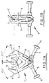
- Figure 1a shows a crimping device 1 of the type described in the above referenced prior art.
- the stuffed casing 2, shown in cross-section in Figure 1a travels around a circular path along which a number of such crimping devices are arranged.
- the crimping device comprises a pair of arms 3,4 each of which is provided with an outer finger 9 and an inner finger 10, the fingers forming a 'V' shape with the apex of the 'V' coinciding with the arms.
- the two arms are pivotally coupled together about a common axis of rotation 7 by means of a spring 8.
- Each arm is provided with a cam follower 5 having an end mounted roller 6 which engages a cam fixed to a central shaft of the apparatus.
- cams (not shown) on the cam followers causes the arms to rotate about axis 7 towards each other to close, compressing the filled casing between the outer surfaces 12 of the inner fingers 10 and the inner surfaces 11 of the outer fingers 9.
- Figure 1b illustrates the arms 3, 4 in the closed position.
- the circular path along which the stuffed casing travels remains of substantially constant length during the crimping process.
- a link can only be formed by stretching the casing when it is crimped, around the shoulder of the sausage as the shoulder forms. This stretching produces considerable strain on the casing and can cause it to rupture. Whilst it may be possible to alleviate this problem by using thicker and stronger casings, this is not always acceptable especially if the casing is intended to be edible.
- apparatus for crimping an elongate filled sausage casing comprising;
- apparatus for crimping an elongate filled sausage casing comprising;
- Each crimping device of the present invention may be provided by a pair of crimping arms coupled for rotation about a common axis of rotation in a scissor-like arrangement.
- the arms may each be provided at their radially outer end with a pair of fingers which substantially define a V shape, the two pairs of fingers being arranged to clamp a filled casing therebetween as the arms are closed.
- the radially innermost fingers of the two arms partially overlap when the arms are open so that their radially outer surfaces define an inner support surface on which a filled casing rests.
- a method of crimping an elongate filled sausage casing comprising the steps of,
- the method includes the steps of,
- the method includes the step of minimising lateral movement of the filled casing during the crimping operation.
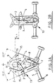
- Figures 2A and 2B show a crimping device suitable for use with otherwise conventional sausage link formation apparatus of the type described, for example, in EP-0139333.
- the crimping device of Figure 2a comprises a very similar structure to that of the conventional crimping device described with reference to Figure 1 (with like parts being identified by like reference numerals) having a pair of crimping arms 3, 4 rotatably coupled by way of a spring 8 about an axis 7.
- the crimping device of Figure 2 significantly differs from that shown in Figure 1 in that the radially inner fingers 10 of the crimping arms are arranged at an angle to the horizontal, with the outer surface of inner fingers 10 having a straight portion 15 continuing into a curved portion 16 which in the open position of arms shown in Figure 2A supports the filled casing at a first radial distance, R 1 , from axis 7. It will be seen that curved positions 16 overlap to form a double inner support surface 16 on which the filled casing rests.
- the arms and fingers are arranged so that when the arms are in the open position (shown in Figure 2a) the filled casing is supported at a first radius of curvature R 1 from axis 7 (with respect to the circular path along which the crimping devices and filled casing move) substantially identical to that of the conventional device as shown in Figure 1a. All points on surface 15, 16 are the same as or less than the first radius of curvature R 1 shown in Figure 2A.
- the radius of curvature R 3 corresponds to the distance of surface 15 from axis 7 near the apex of the arms ( Figure 2B).
- Figure 1b shows that with the conventional crimping device the support surface moves radially outwardly when the arms are closed, leaving the position of the filled casing substantially unchanged but the support surface can only compress the filled casing by stretching the casing which, as mentioned above can result in casing rupture.
- the crimping devices are spaced about a circular path 17 and carry the elongate filled casing around this path 17 as they are rotated about an axis 18.
- the crimping devices are operated by means of a cam (not shown in the Figures) which acts on the cam followers 6 so as to actuate adjacent crimping means substantially simultaneously.
- a cam not shown in the Figures
- the respective casing support surfaces are displaced in a radially inward direction as described above.
- the outer surface 15 of each of the inner fingers 14 should lie substantially within a circle centred on the rotation axis 7 of the arms and passing through the support surface 16, when the arms are open.
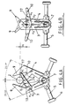
- Figures 4a and 4b show a modification to the crimping device of Figure 2.
- the radially inner fingers 10 are lengthening so that each surface 16 is shaped to form a support curve in which the filled casing rests. Overlapping the support curves effectively cradles the filled casing 2.
- This arrangement has the advantage in that it substantially prevents lateral movement of the filled casing which may otherwise cause the casing to move or fall off the support surface 17 and which would give rise to a non-uniform crimping action.
- other forms of lateral support may be provided, for example a pair of vertically extending spaced apart supports.
- the initial radius of curvature from axis 7 is greater than the radius curvature at a point along surface of the arm (R2) and the radius of curvature (R 3 ) near the apex.
- the present invention is not limited to the embodiment described above and it will be appreciated by the skilled person that various modifications may be made.
- the invention encompasses using the crimping devices of Figure 1 with additional mechanically coupled means for moving the crimping device radially inwardly as the crimping surfaces are brought together.
- the present invention may be employed on linear production lines with means being provided for moving adjacent crimping devices closer together as crimping is performed.
- the support surface profile can be such that it has a portion with a radius of curvature less than the initial radius of curvature and a portion greater than the initial radius of curvature, the crimping occurring as the portion with the smaller radius of curvature moves from the open to the closed position.
- the shape and position of the upper arms in each crimping device is such as to facilitate centring of the sausage during crimping without causing stretching of the casing sufficient to cause rupture.
Landscapes
- Life Sciences & Earth Sciences (AREA)
- Engineering & Computer Science (AREA)
- Wood Science & Technology (AREA)
- Zoology (AREA)
- Food Science & Technology (AREA)
- Processing Of Meat And Fish (AREA)
- Containers And Plastic Fillers For Packaging (AREA)
- Meat, Egg Or Seafood Products (AREA)
- Food-Manufacturing Devices (AREA)
- Supports For Pipes And Cables (AREA)
- Pharmaceuticals Containing Other Organic And Inorganic Compounds (AREA)
- Plural Heterocyclic Compounds (AREA)
- Wrapping Of Specific Fragile Articles (AREA)
Claims (8)
- Vorrichtung zum Zusammenpressen einer länglichen gefüllten Würstchenumhüllung, wobei die Vorrichtung folgendes umfaßt:mindestens zwei beabstandete Zusammenpreßvorrichtungen (1), wobei jede Zusammenpreßvorrichtung (1) eine Mehrzahl von Zusammenpreßoberflächen (11, 15, 16) aufweist, welche in einer ersten Position einen Durchgang durch jede der Zusammenpreßvorrichtungen (1) zur Aufnahme und zum Halten der gefüllten Umhüllung ausbilden; undBetätigungsmittel (6), die mit jeder der Zusammenoreßvorrichtungen (1) verbunden sind, um ausgewählte Zusammenpreßvorrichtungen (1) im wesentlichen gleichzeitig zu betätigen, um zwei benachbarte der Durchgänge um die gefüllte Umhüllung zu schließen, um ein Paar benachbarter zusammengepreßter Bereiche zu bilden, welche ein Würstchenelement zwischen dem Paar zusammengepreßter Bereiche ausbilden,
dadurch gekennzeichnet, daß das Betätigungsmittel (6) angeordnet ist, um die beiden Durchgänge bei Schließung der Durchgänge enger zusammen zu bewegen. - Vorrichtung zum Zusammenpressen einer länglichen gefüllten Würstchenumhüllung, wobei die Vorrichtung folgendes umfaßt:Mittel, die einen im wesentlichen kreisförmigen Weg (17) ausbilden, wobei eine gefüllte Würstchenumhüllung so angeordnet ist, daß sie sich entlang des Weges bewegt;eine Mehrzahl an Zusammenpreßvorrichtungen (1), welche in Intervallen um den kreisförmigen Weg (17) angeordnet sind, wobei jede Zusammenpreßvorrichtung (1) eine Mehrzahl an Zusammenpreßoberflächen (11, 15, 16) aufweist, welche in einer ersten Position einen Durchgang durch die Zusammenpreßvorrichtung (1) zur Aufnahme und zum Halten der gefüllten Umhüllung ausbilden; undBetätigungsmittel (6), die mit jeder der Zusammenpreßvorrichtungen (1) verbunden sind, um die Zusammenpreßvorrichtungen (1) im wesentlichen gleichzeitig zu betätigen, um mindestens zwei benachbarte Durchgänge um die aufgenommene Umhüllung zu schließen, um ein Paar benachbarter zusammengepreßter Bereiche zu bilden,
dadurch gekennzeichnet, daß das Betätigungsmittel (6) ebenso angeordnet ist, um die beiden Durchgänge der mindestens zwei benachbarten Zusammenpreßvorrichtungen (1) in einer radial einwärts gerichteten Richtung zu versetzen, wodurch, wenn die Würstchenumhüllung zusammengepreßt wird, diese axial von ihrer ursprünglich gehaltenen Länge gekürzt wird. - Vorrichtung gemäß Anspruch 1 oder 2, bei der jede Zusammenpreßvorrichtung (1) durch ein Paar Zusammenpreßarme (3, 4) in einer Verbindung zur Drehung um eine gemeinsame Drehachse (7) in scherenartiger Anordnung zur Verfügung gestellt ist.
- Vorrichtung gemäß Anspruch 3, bei der jeder Arm (3, 4) an seinem radial äußeren Ende mit einem Paar Fingern (9, 10) versehen ist, welche im wesentlichen eine V-Form ausbilden, wobei die beiden Finger (9, 10) angeordnet sind, um eine gefüllte Umhüllung dazwischen zu klemmen, wenn die Arme (3, 4) geschlossen sind.
- Vorrichtung gemäß Anspruch 4, bei der die radial innersten Finger (10) der beiden Arme (3, 4) teilweise überlappen, wenn die (3, 4) Arme offen sind, so daß ihre radial äußeren Oberflächen eine innere Halteoberfläche ausbilden (15), worin eine gefüllte Umhüllung ruht.
- Vorrichtung zum Zusammenpressen einer länglichen gefüllten Würstchenumhüllung, wobei das Verfahren folgende Schritte umfaßt:Halten der länglichen gefüllten Umhüllung an mindestens zwei Positionen entlang ihrer Länge; undZusammenpressen der gefüllten Umhüllung an den mindestens zwei Positionen im wesentlichen zur selben Zeit,
gekennzeichnet durch den Schritt der gleichzeitigen Bewegung der mindestens zwei Positionen in Richtung aufeinander, wenn das Zusammenpressen erfolgt, so daß die Länge der gefüllten Umhüllung zwischen den mindestens zwei Positionen im Vergleich zu ihrer ursprünglichen Länge gekürzt wird. - Verfahren gemäß Anspruch 6, bei dem das Verfahren den Schritt des Haltens der länglichen Umhüllung entlang eines Umfangswegs und Bewegung der gehaltenen Positionen radial einwärts von dem Weg bei Ausführung des Zusammenpreßvorgangs umfaßt.
- Verfahren gemäß Anspruch 6 oder 7, wobei das Verfahren den Schritt der Minimierung einer lateralen Bewegung der gefüllten Umhüllung während des Zusammenpreßvorgangs umfaßt.
Applications Claiming Priority (3)
| Application Number | Priority Date | Filing Date | Title |
|---|---|---|---|
| GB9415027 | 1994-07-26 | ||
| GB9415027A GB9415027D0 (en) | 1994-07-26 | 1994-07-26 | Apparatus and method for crimping sausage links and ends |
| PCT/GB1995/001615 WO1996003050A1 (en) | 1994-07-26 | 1995-07-10 | Apparatus and method for crimping sausage links and ends |
Publications (2)
| Publication Number | Publication Date |
|---|---|
| EP0772401A1 EP0772401A1 (de) | 1997-05-14 |
| EP0772401B1 true EP0772401B1 (de) | 1998-11-04 |
Family
ID=10758873
Family Applications (1)
| Application Number | Title | Priority Date | Filing Date |
|---|---|---|---|
| EP95924433A Expired - Lifetime EP0772401B1 (de) | 1994-07-26 | 1995-07-10 | Verfahren und vorrichtung zum gliedern von wurstabschnitten |
Country Status (12)
| Country | Link |
|---|---|
| EP (1) | EP0772401B1 (de) |
| JP (1) | JPH10511844A (de) |
| AT (1) | ATE172850T1 (de) |
| AU (1) | AU684970B2 (de) |
| BR (1) | BR9508444A (de) |
| CA (1) | CA2195853A1 (de) |
| DE (1) | DE69505821T2 (de) |
| ES (1) | ES2123263T3 (de) |
| FI (1) | FI970333A7 (de) |
| GB (1) | GB9415027D0 (de) |
| NO (1) | NO970346L (de) |
| WO (1) | WO1996003050A1 (de) |
Families Citing this family (1)
| Publication number | Priority date | Publication date | Assignee | Title |
|---|---|---|---|---|
| NL1025005C2 (nl) * | 2003-12-12 | 2005-06-14 | Townsend Engineering B V | Werkwijze voor het gefaseerd separeren van een worststreng, separatie-element en samenstel van separatie-elementen. |
Family Cites Families (5)
| Publication number | Priority date | Publication date | Assignee | Title |
|---|---|---|---|---|
| US1564588A (en) * | 1925-01-26 | 1925-12-08 | Henry Cohn | Sausage-forming machine |
| US3487500A (en) * | 1967-08-03 | 1970-01-06 | Armour & Co | Apparatus for linking sausage strands |
| DE2550042C2 (de) * | 1975-11-07 | 1982-12-02 | Herbert Dipl.-Ing. 6240 Königstein Niedecker | Vorrichtung zum Abteilen von Packungen von einem gefüllten Schlauch |
| US4418447A (en) * | 1981-07-02 | 1983-12-06 | Devro, Inc. | Method and apparatus for processing stuffed sausage casing |
| US4549330A (en) * | 1983-09-30 | 1985-10-29 | Devro, Inc. | Apparatus for preparing sausage links |
-
1994
- 1994-07-26 GB GB9415027A patent/GB9415027D0/en active Pending
-
1995
- 1995-07-10 ES ES95924433T patent/ES2123263T3/es not_active Expired - Lifetime
- 1995-07-10 CA CA002195853A patent/CA2195853A1/en not_active Abandoned
- 1995-07-10 AU AU28933/95A patent/AU684970B2/en not_active Ceased
- 1995-07-10 DE DE69505821T patent/DE69505821T2/de not_active Expired - Fee Related
- 1995-07-10 WO PCT/GB1995/001615 patent/WO1996003050A1/en not_active Ceased
- 1995-07-10 BR BR9508444A patent/BR9508444A/pt not_active IP Right Cessation
- 1995-07-10 JP JP8505551A patent/JPH10511844A/ja active Pending
- 1995-07-10 EP EP95924433A patent/EP0772401B1/de not_active Expired - Lifetime
- 1995-07-10 AT AT95924433T patent/ATE172850T1/de not_active IP Right Cessation
-
1997
- 1997-01-27 FI FI970333A patent/FI970333A7/fi unknown
- 1997-01-27 NO NO970346A patent/NO970346L/no unknown
Also Published As
| Publication number | Publication date |
|---|---|
| CA2195853A1 (en) | 1996-02-08 |
| DE69505821T2 (de) | 1999-07-08 |
| GB9415027D0 (en) | 1994-09-14 |
| BR9508444A (pt) | 1997-11-25 |
| FI970333A0 (fi) | 1997-01-27 |
| NO970346L (no) | 1997-03-24 |
| AU2893395A (en) | 1996-02-22 |
| ATE172850T1 (de) | 1998-11-15 |
| ES2123263T3 (es) | 1999-01-01 |
| EP0772401A1 (de) | 1997-05-14 |
| JPH10511844A (ja) | 1998-11-17 |
| AU684970B2 (en) | 1998-01-08 |
| WO1996003050A1 (en) | 1996-02-08 |
| NO970346D0 (no) | 1997-01-27 |
| FI970333A7 (fi) | 1997-03-21 |
| DE69505821D1 (de) | 1998-12-10 |
Similar Documents
| Publication | Publication Date | Title |
|---|---|---|
| CA1184065A (en) | Method and apparatus for processing stuffed sausage casing | |
| CA1174106A (en) | Apparatus for and process of controlled sub-volume filling of casings | |
| EP0772401B1 (de) | Verfahren und vorrichtung zum gliedern von wurstabschnitten | |
| JP4204145B2 (ja) | ソーセージ等の食品を製造する方法及び装置 | |
| FI83282C (fi) | Rynkat roerformat material. | |
| EP0693880B1 (de) | Verfahren und vorrichtung zum herstellen von wurststrängen | |
| US4549330A (en) | Apparatus for preparing sausage links | |
| GB2299742A (en) | Making sausages | |
| CA2403078C (en) | Method and apparatus for precrimping a sausage strand | |
| US4420856A (en) | Apparatus for processing stuffed sausage casing | |
| JPH07505532A (ja) | 回転自在なリンキングおよび吊下げ装置 | |
| AU2001238727A1 (en) | Method and apparatus for precrimping a sausage strand | |
| EP0781509B1 (de) | Maschine zum Unterteilen einer kontinuierlichen Wurst in Würste mit verdrillter Hülle | |
| US3942569A (en) | Unilaterally closed hollow stick of shirred sausage casing with an inner closure formed from the tubular casing itself | |
| GB2211461A (en) | Dough shaping | |
| US3971301A (en) | Process for the production of the closure of a hollow stick of shirred sausage casing | |
| JP2003529351A5 (de) | ||
| JP3815568B2 (ja) | 襞模様形成装置及び方法 | |
| US4596064A (en) | Method for manufacturing a screw flight | |
| SU1761084A1 (ru) | Устройство дл наложени скрепок на концы колбасных батонов | |
| PL62449B1 (de) |
Legal Events
| Date | Code | Title | Description |
|---|---|---|---|
| PUAI | Public reference made under article 153(3) epc to a published international application that has entered the european phase |
Free format text: ORIGINAL CODE: 0009012 |
|
| 17P | Request for examination filed |
Effective date: 19970122 |
|
| AK | Designated contracting states |
Kind code of ref document: A1 Designated state(s): AT BE CH DE DK ES FR GB GR IE IT LI LU MC NL PT SE |
|
| RAP1 | Party data changed (applicant data changed or rights of an application transferred) |
Owner name: DEVRO-TEEPAK LIMITED |
|
| RAP1 | Party data changed (applicant data changed or rights of an application transferred) |
Owner name: DEVRO PLC |
|
| GRAG | Despatch of communication of intention to grant |
Free format text: ORIGINAL CODE: EPIDOS AGRA |
|
| 17Q | First examination report despatched |
Effective date: 19971002 |
|
| GRAG | Despatch of communication of intention to grant |
Free format text: ORIGINAL CODE: EPIDOS AGRA |
|
| GRAH | Despatch of communication of intention to grant a patent |
Free format text: ORIGINAL CODE: EPIDOS IGRA |
|
| GRAH | Despatch of communication of intention to grant a patent |
Free format text: ORIGINAL CODE: EPIDOS IGRA |
|
| GRAA | (expected) grant |
Free format text: ORIGINAL CODE: 0009210 |
|
| AK | Designated contracting states |
Kind code of ref document: B1 Designated state(s): AT BE CH DE DK ES FR GB GR IE IT LI LU MC NL PT SE |
|
| PG25 | Lapsed in a contracting state [announced via postgrant information from national office to epo] |
Ref country code: SE Free format text: THE PATENT HAS BEEN ANNULLED BY A DECISION OF A NATIONAL AUTHORITY Effective date: 19981104 Ref country code: LI Free format text: LAPSE BECAUSE OF FAILURE TO SUBMIT A TRANSLATION OF THE DESCRIPTION OR TO PAY THE FEE WITHIN THE PRESCRIBED TIME-LIMIT Effective date: 19981104 Ref country code: CH Free format text: LAPSE BECAUSE OF FAILURE TO SUBMIT A TRANSLATION OF THE DESCRIPTION OR TO PAY THE FEE WITHIN THE PRESCRIBED TIME-LIMIT Effective date: 19981104 Ref country code: AT Free format text: LAPSE BECAUSE OF FAILURE TO SUBMIT A TRANSLATION OF THE DESCRIPTION OR TO PAY THE FEE WITHIN THE PRESCRIBED TIME-LIMIT Effective date: 19981104 |
|
| REF | Corresponds to: |
Ref document number: 172850 Country of ref document: AT Date of ref document: 19981115 Kind code of ref document: T |
|
| REG | Reference to a national code |
Ref country code: CH Ref legal event code: EP |
|
| REF | Corresponds to: |
Ref document number: 69505821 Country of ref document: DE Date of ref document: 19981210 |
|
| ET | Fr: translation filed | ||
| REG | Reference to a national code |
Ref country code: ES Ref legal event code: FG2A Ref document number: 2123263 Country of ref document: ES Kind code of ref document: T3 |
|
| REG | Reference to a national code |
Ref country code: IE Ref legal event code: FG4D |
|
| PG25 | Lapsed in a contracting state [announced via postgrant information from national office to epo] |
Ref country code: PT Free format text: LAPSE BECAUSE OF FAILURE TO SUBMIT A TRANSLATION OF THE DESCRIPTION OR TO PAY THE FEE WITHIN THE PRESCRIBED TIME-LIMIT Effective date: 19990204 Ref country code: DK Free format text: LAPSE BECAUSE OF FAILURE TO SUBMIT A TRANSLATION OF THE DESCRIPTION OR TO PAY THE FEE WITHIN THE PRESCRIBED TIME-LIMIT Effective date: 19990204 |
|
| REG | Reference to a national code |
Ref country code: CH Ref legal event code: PL |
|
| PGFP | Annual fee paid to national office [announced via postgrant information from national office to epo] |
Ref country code: GB Payment date: 19990707 Year of fee payment: 5 |
|
| PGFP | Annual fee paid to national office [announced via postgrant information from national office to epo] |
Ref country code: FR Payment date: 19990709 Year of fee payment: 5 |
|
| PG25 | Lapsed in a contracting state [announced via postgrant information from national office to epo] |
Ref country code: LU Free format text: LAPSE BECAUSE OF NON-PAYMENT OF DUE FEES Effective date: 19990710 Ref country code: IE Free format text: LAPSE BECAUSE OF NON-PAYMENT OF DUE FEES Effective date: 19990710 |
|
| PGFP | Annual fee paid to national office [announced via postgrant information from national office to epo] |
Ref country code: DE Payment date: 19990712 Year of fee payment: 5 |
|
| PGFP | Annual fee paid to national office [announced via postgrant information from national office to epo] |
Ref country code: ES Payment date: 19990719 Year of fee payment: 5 |
|
| PGFP | Annual fee paid to national office [announced via postgrant information from national office to epo] |
Ref country code: NL Payment date: 19990730 Year of fee payment: 5 Ref country code: GR Payment date: 19990730 Year of fee payment: 5 |
|
| PLBE | No opposition filed within time limit |
Free format text: ORIGINAL CODE: 0009261 |
|
| STAA | Information on the status of an ep patent application or granted ep patent |
Free format text: STATUS: NO OPPOSITION FILED WITHIN TIME LIMIT |
|
| PGFP | Annual fee paid to national office [announced via postgrant information from national office to epo] |
Ref country code: BE Payment date: 19990915 Year of fee payment: 5 |
|
| 26N | No opposition filed | ||
| PG25 | Lapsed in a contracting state [announced via postgrant information from national office to epo] |
Ref country code: MC Free format text: LAPSE BECAUSE OF NON-PAYMENT OF DUE FEES Effective date: 20000131 |
|
| REG | Reference to a national code |
Ref country code: IE Ref legal event code: MM4A |
|
| PG25 | Lapsed in a contracting state [announced via postgrant information from national office to epo] |
Ref country code: GB Free format text: LAPSE BECAUSE OF NON-PAYMENT OF DUE FEES Effective date: 20000710 |
|
| PG25 | Lapsed in a contracting state [announced via postgrant information from national office to epo] |
Ref country code: ES Free format text: LAPSE BECAUSE OF NON-PAYMENT OF DUE FEES Effective date: 20000711 |
|
| PG25 | Lapsed in a contracting state [announced via postgrant information from national office to epo] |
Ref country code: GR Free format text: LAPSE BECAUSE OF NON-PAYMENT OF DUE FEES Effective date: 20000731 Ref country code: BE Free format text: LAPSE BECAUSE OF NON-PAYMENT OF DUE FEES Effective date: 20000731 |
|
| BERE | Be: lapsed |
Owner name: DEVRO P.L.C. Effective date: 20000731 |
|
| PG25 | Lapsed in a contracting state [announced via postgrant information from national office to epo] |
Ref country code: NL Free format text: LAPSE BECAUSE OF NON-PAYMENT OF DUE FEES Effective date: 20010201 |
|
| GBPC | Gb: european patent ceased through non-payment of renewal fee |
Effective date: 20000710 |
|
| PG25 | Lapsed in a contracting state [announced via postgrant information from national office to epo] |
Ref country code: FR Free format text: LAPSE BECAUSE OF NON-PAYMENT OF DUE FEES Effective date: 20010330 |
|
| NLV4 | Nl: lapsed or anulled due to non-payment of the annual fee |
Effective date: 20010201 |
|
| REG | Reference to a national code |
Ref country code: FR Ref legal event code: ST |
|
| PG25 | Lapsed in a contracting state [announced via postgrant information from national office to epo] |
Ref country code: DE Free format text: LAPSE BECAUSE OF NON-PAYMENT OF DUE FEES Effective date: 20010501 |
|
| REG | Reference to a national code |
Ref country code: ES Ref legal event code: FD2A Effective date: 20020306 |
|
| PG25 | Lapsed in a contracting state [announced via postgrant information from national office to epo] |
Ref country code: IT Free format text: LAPSE BECAUSE OF NON-PAYMENT OF DUE FEES Effective date: 20050710 |