EP0773519A2 - Machine de vente pour charger une batterie secondaire d'un mobilophone - Google Patents
Machine de vente pour charger une batterie secondaire d'un mobilophone Download PDFInfo
- Publication number
- EP0773519A2 EP0773519A2 EP96118202A EP96118202A EP0773519A2 EP 0773519 A2 EP0773519 A2 EP 0773519A2 EP 96118202 A EP96118202 A EP 96118202A EP 96118202 A EP96118202 A EP 96118202A EP 0773519 A2 EP0773519 A2 EP 0773519A2
- Authority
- EP
- European Patent Office
- Prior art keywords
- charging
- secondary battery
- mobile phone
- battery
- terminal voltage
- Prior art date
- Legal status (The legal status is an assumption and is not a legal conclusion. Google has not performed a legal analysis and makes no representation as to the accuracy of the status listed.)
- Withdrawn
Links
Images







Classifications
-
- G—PHYSICS
- G06—COMPUTING OR CALCULATING; COUNTING
- G06Q—INFORMATION AND COMMUNICATION TECHNOLOGY [ICT] SPECIALLY ADAPTED FOR ADMINISTRATIVE, COMMERCIAL, FINANCIAL, MANAGERIAL OR SUPERVISORY PURPOSES; SYSTEMS OR METHODS SPECIALLY ADAPTED FOR ADMINISTRATIVE, COMMERCIAL, FINANCIAL, MANAGERIAL OR SUPERVISORY PURPOSES, NOT OTHERWISE PROVIDED FOR
- G06Q20/00—Payment architectures, schemes or protocols
- G06Q20/08—Payment architectures
- G06Q20/12—Payment architectures specially adapted for electronic shopping systems
- G06Q20/127—Shopping or accessing services according to a time-limitation
-
- H—ELECTRICITY
- H02—GENERATION; CONVERSION OR DISTRIBUTION OF ELECTRIC POWER
- H02J—ELECTRIC POWER NETWORKS; CIRCUIT ARRANGEMENTS OR SYSTEMS FOR SUPPLYING OR DISTRIBUTING ELECTRIC POWER; SYSTEMS FOR STORING ELECTRIC ENERGY
- H02J7/00—Circuit arrangements for charging or discharging batteries or for supplying loads from batteries
- H02J7/02—Circuit arrangements for charging or discharging batteries or for supplying loads from batteries for charging batteries from AC mains by converters
-
- G—PHYSICS
- G07—CHECKING-DEVICES
- G07F—COIN-FREED OR LIKE APPARATUS
- G07F15/00—Coin-freed apparatus with meter-controlled dispensing of liquid, gas or electricity
- G07F15/003—Coin-freed apparatus with meter-controlled dispensing of liquid, gas or electricity for electricity
-
- G—PHYSICS
- G07—CHECKING-DEVICES
- G07F—COIN-FREED OR LIKE APPARATUS
- G07F15/00—Coin-freed apparatus with meter-controlled dispensing of liquid, gas or electricity
- G07F15/003—Coin-freed apparatus with meter-controlled dispensing of liquid, gas or electricity for electricity
- G07F15/006—Coin-freed apparatus with meter-controlled dispensing of liquid, gas or electricity for electricity dispensed for the electrical charging of other devices than vehicles
-
- G—PHYSICS
- G07—CHECKING-DEVICES
- G07F—COIN-FREED OR LIKE APPARATUS
- G07F15/00—Coin-freed apparatus with meter-controlled dispensing of liquid, gas or electricity
- G07F15/04—Coin-freed apparatus with meter-controlled dispensing of liquid, gas or electricity in which the quantity mechanism is set forward automatically by the insertion of a coin
-
- G—PHYSICS
- G07—CHECKING-DEVICES
- G07F—COIN-FREED OR LIKE APPARATUS
- G07F17/00—Coin-freed apparatus for hiring articles; Coin-freed facilities or services
- G07F17/0014—Coin-freed apparatus for hiring articles; Coin-freed facilities or services for vending, access and use of specific services not covered anywhere else in G07F17/00
-
- H—ELECTRICITY
- H04—ELECTRIC COMMUNICATION TECHNIQUE
- H04M—TELEPHONIC COMMUNICATION
- H04M19/00—Current supply arrangements for telephone systems
- H04M19/08—Current supply arrangements for telephone systems with current supply sources at the substations
Definitions
- the present invention relates to a vending machine for charging a secondary battery of a mobile phone, a vending system composed of at least one first unit which includes a plurality of charging apparatus, each for charging a secondary battery (so called rechargeable battery ) of a mobile phone and a second unit for performing charging control, and a charging apparatus used in a vending machine or vending system for charging a secondary battery of a mobile phone.
- a vending machine for charging a secondary battery of a mobile phone
- a vending system composed of at least one first unit which includes a plurality of charging apparatus, each for charging a secondary battery (so called rechargeable battery ) of a mobile phone and a second unit for performing charging control
- a charging apparatus used in a vending machine or vending system for charging a secondary battery of a mobile phone.
- a maximum continuous waiting time and/or a maximum continuous talking time of respective mobile phones is usually preset in accordance with the capacity of an installed secondary battery in the mobile phone. Accordingly, it is needed to charge the secondary battery due to the lack of the remaining capacity thereof when the mobile phone is used for a long time.
- the mobile phone's holder in order to charge a secondary battery of a mobile phone, the mobile phone's holder must take back it to his( or her) office or his( or her) home and set it on a dedicated charger, such as a desk-type quick charger.
- the Ni-Cd battery and Ni-MH battery have characteristics such that the temperature of the secondary battery will suddenly rise up and the terminal voltage of the secondary battery will suddenly change when the secondary battery reaches full-charged condition or overcharged condition. Accordingly, it is necessary to incorporate a charge control circuit into the charging apparatus, for adequately controlling the charging operation for a the secondary battery.
- a Li-ION battery as a secondary battery is usually charged by a charging apparatus employing a constant current and constant voltage charging method. Accordingly, it is necessary to control the charging apparatus such that the constant current charge is switched to a constant voltage charge when the terminal voltage of the Li-ION battery reaches the rated charging voltage. Therefore, it is necessary to design the charging apparatus to minimize the detection error of the terminal voltage of the Li-ION battery. Furthermore, it is required to precisely detect the full-charged (or 100% charged) condition in the Li-ION battery, in order to prevent it from catching fire or giving out smoke, due to the overcharge thereof.
- the conventional charging apparatus for charging a secondary battery is designed, assuming that a full-charge must be performed. Furthermore, many charge control techniques for preventing an occurrence of an accident due to overcharging have been proposed.
- a mobile phone's holder must take back it to his( or her) office or his( or her) home in order to charge the completely or partially discharged secondary battery of the mobile phone.
- a secondary battery of a portable electric device when a secondary battery of a portable electric device has been completely consumed and it becomes to be necessary to recharge the secondary battery, the user does not always require that the secondary battery be fully charged up.
- the secondary battery when a mobile phone's holder is out with the mobile phone, and the secondary battery of the mobile phone has been completely consumed, there is a case where the holder has to urgently use the mobile phone although it is necessary to recharge the secondary battery. In such a case, it would be good enough if the holder is able to use the mobile phone for only five(5) or ten(10) minutes by quickly recharging the secondary battery. That is to say, it would be sufficient to not fully (100%) but partially (several tens % of full-charged condition) charge the secondary battery in such a manner that the holder can use the mobile phone for a short time.
- vending machine which provides a quick charger conveniently to charge a secondary battery of a portable electric device so as to make the device operable for a short period of time when an user carries the device outdoors and the secondary battery runs out.
- the present invention therefore, has as its principal object to provide a vending machine for conveniently charging an empty secondary battery of a mobile phone, when a holder of the mobile phone carries outdoors, without taking back it to his/her office or home.
- a vending machine for charging a secondary battery of a mobile phone which comprises a plurality of charging means, each conforming to a specification of a mobile phone and a secondary battery of the mobile phone, for charging plural kinds of secondary batteries used in plural kinds of mobile phones; instruction means for instructing a charging time corresponding to each of the plurality of charging means; lock/unlock means for locking/unlocking a key on a door provided in each of the plurality of charging means; reception means for receiving at least one coin and/or at least one banknote; calculation means for calculating an amount of money of the coin and/or banknote which have been received in the reception means; and charging control means for controlling each of the plurality of charging means to charge a secondary battery of a mobile phone attached in one of the plurality of charging means, in accordance with the amount of money calculated by the calculation means and the charging time instructed by the instruction means.
- a mobile phone's holder finds charging means suitable for his/her own mobile phone from a plurality of charging means, each conforming to a specification of a mobile phone and a second battery of the mobile phone, attaches the mobile phone to the charging means, inserts an appropriate amount of coin or banknote into reception means, instructs his/her desired charging time from instruction means, and locks the charging means by lock/unlock means, the machine calculates the amount of received coin or banknote, controls the charging means in accordance with the calculated amount and the instructed time such that the charging means charges the secondary battery of the mobile phone attached to the charging means.
- the calculation means includes comparison means for comparing the amount of money of the coin and/or banknote received in the reception means with an amount of money equivalent to the charging time instructed by the instruction means; and change control means for controlling to make change in accordance with the comparison result from the comparison means.
- each of the plurality of charging means includes a quick charger conforming to a predetermined type of mobile phone and a predetermined type of secondary battery, for quickly charging the secondary battery attached to the corresponding charging means; and display means for displaying status of charging operation of the quick charger.
- the quick charger includes at least two electrodes through which the electric power is to be supplied to the secondary battery, and positions of said electrodes, a shape of each of the electrodes and a charging voltage of the quick charger are uniquely defined according to a specification of the mobile phone and the secondary battery attached thereto.
- the display means includes a plurality of LEDs (light emitting devices), each of which lights in a different color, and is turned on in accordance with progress of charging operation.
- LEDs light emitting devices
- the plurality of secondary batteries include at least a Ni-Cd battery, a Ni-MH battery and a Li-ION battery.
- the charging control means includes sensing means for sensing whether or not the door in the charging means is locked by the lock/unlock means, and start control means for controlling start of charging the secondary battery of the mobile phone which has been attached in the charging means in accordance with the sensing result from the sensing means.
- the quick charger may include a holder for holding an electric contact with the electrodes of the secondary battery, a voltmeter for measuring a terminal voltage of the secondary battery, a differentiation circuit for measuring a change rate in time of the terminal voltage, a constant current charging circuit for quickly charging the secondary battery, a first comparator for comparing the terminal voltage measured by the voltmeter with a predetermined charging voltage defined for the secondary battery, a second comparator for measuring the change rate in time of the terminal voltage measured by the differentiation circuit with a predetermined threshold, a register for setting the predetermined threshold, and a controller for performing control in accordance with the comparison results by the first and second comparators such that charging operation in the constant current charging circuit is halted before the secondary battery reaches full-charged condition.
- the controller further performs control such that charging operation is halted when it is determined in accordance with the comparison result by the first comparator that the measured terminal voltage exceeds a predetermined charged voltage. More preferably, when the determination is made, the secondary battery reaches within a range from approximately 60% to 90% of the full-charged condition
- the second comparator employs a value very close to "0" as the predetermined threshold.
- the quick charger may also include a holder for holding an electric contact with electrodes of the secondary battery, measuring means for measuring a terminal voltage of the secondary battery, comparison means for comparing the terminal voltage measured by the measuring means with a predetermined limited voltage defined for the secondary battery, charging means for quickly charging the secondary battery, and charging control means for performing control in accordance with the comparison results by the comparison means such that charging operation in the charging means is halted before the secondary battery reaches full-charged condition.
- the predetermined limited voltage is defined within a range from approximately 60% to approximately 90% of the maximum charging voltage defined for the secondary battery.
- a charging apparatus for charging a secondary battery which comprises a holder for holding an electric contact with electrodes of the secondary battery, first measuring means for measuring a terminal voltage of the secondary battery, second measuring means for measuring a change rate in time of the terminal voltage, charging means for quickly charging the secondary battery, a first comparison means for comparing the terminal voltage measured by the first measuring means with a predetermined charging voltage defined for the secondary battery, a second comparison means for comparing the change rate in time of the terminal voltage measured by the second measuring means with a predetermined threshold, and charging control means for performing control in accordance with the comparison results by the first and second comparators such that charging operation in the charging means is halted before the secondary battery reaches full-charged condition.
- a terminal voltage of the secondary battery and a change rate in time of the terminal voltage are measured, the measured terminal voltage is compared with a predetermined charging voltage defined for the secondary battery, the measured change rate in time of the terminal voltage is further compared with a predetermined threshold. And, control is performed in accordance with these comparison results such that the charging operation is halted before the secondary battery reaches full-charged condition.
- the charging means includes a constant current charging circuit for quickly charging the secondary battery at a constant current, a voltmeter for measuring a terminal voltage of the secondary battery, and a differentiation circuit for measuring a change rate in time of the terminal voltage.
- the apparatus further comprises a register for setting the predetermined threshold.
- the charging control means performs control such that charging operation is halted when it is determined in accordance with the comparison result by the first comparison means that the terminal voltage exceeds the predetermined charging voltage.
- the second comparison means employs a value very close to "0" as the predetermined threshold.
- the secondary batteries include at least a Ni-Cd battery, a Ni-MH battery and a Li-ION battery.
- the charging control means performs control such that the charging operation is halted when it is determined that the secondary battery reaches within a range from approximately 60% to 90% of the full-charged condition.
- a charging apparatus for charging a secondary battery which comprises a holder for holding an electric contact with electrodes of the secondary battery, measuring means for measuring a terminal voltage of the secondary battery, comparison means for comparing the terminal voltage measured by the measuring means with a predetermined limited voltage defined for the secondary battery, charging means for quickly charging the secondary battery, and charging control means for performing control in accordance with the comparison results by the comparison means such that charging operation in the charging means is halted before the secondary battery reaches full-charged condition.
- the charging means includes a constant current charging circuit for charging at a constant current.
- the measurement means includes a voltmeter.
- the secondary batteries include at least a Ni-Cd battery, a Ni-MH battery and a Li-ION battery.
- the charging operation is halted when it is determined that the terminal voltage measured by the measuring means reaches approximately 60% to 90% of the maximum charged voltage defined for the secondary battery.
- the foregoing object is attain by providing a vending system composed of at least one first unit which includes a plurality of charging means, each conforming to a specification of a mobile phone and a secondary battery of the mobile phone, for charging plural kinds of secondary batteries used in plural kinds of mobile phones, and a second unit which performs charging control on each of the plurality of charging means, which comprises first extension means for electrically connecting at most a first predetermined number of the first units to the second unit, and second extension means for mechanically connecting plural number of sets, each composed of the first predetermined number of the first units and one second unit, with each other.
- the second unit includes display means for displaying a guidance concerning with the charging operation with respect to each of the plurality of charging means, instruction means for instructing a charging time corresponding to each of the plurality of charging means, lock/unlock means for locking/unlocking a key on a door provided in each of the plurality of charging means, and output means for outputting an information for unlocking the key on the door.
- the display means includes an LCD (liquid crystal device), the instruction means includes ten-keys, and the output means includes a printer.
- the second unit further includes reception means for receiving at least one coin and/or at least one banknote, calculation means for calculating an amount of money of the coin and/or bill which have been received in the reception means, and change control means for calculating a change based on the amount of money calculated by the calculation means and the charging time instructed by the instruction means, and controlling change return in accordance with the calculation result if necessary.
- the plurality of secondary batteries include at least a Ni-Cd battery, a Ni-MH battery and a Li-ION battery.
- each of the plurality of charging means in the first unit includes LEDs, each of which lights in a different color, and is turned on in accordance with progress of charging operation.
- the invention is particularly advantageous since a mobile phone's holder can conveniently charge his/her own mobile phone by installing a vending machine according to the present invention at a public place such as a station, shopping mall, and hotel. If the vending machine is available, even though a secondary battery of a mobile phone runs out due to longtime operation, the holder can conveniently use the machine near by, and can recharge the secondary battery. As a result of this, the holder becomes free from carrying around an extra battery package.
- charging operation according to the present invention enables a portable electric device employing a secondary battery as a power source to be operable for the time being even though the charging operation does not fulfill 100% charge. Since the charging operation does not perform full-charge, it is not necessary for a charging apparatus performing the charging operation to incorporate complicated charging control which takes into consideration overcharge ,and overheat and firing due to the overcharge. Thus, this contributes to simplifying the construction of circuit in the charging apparatus.
- a vending machine of the present embodiment is provided for selling electric power which is used to charge a mobile phone.
- the mobile phone is comprised of a phone body and a secondary battery which is detachably attached to the phone body.
- the secondary battery is of a Ni-Cd (nickel-cadmium) type in the present embodiment and set to be chargeable. It should be noted that the secondary battery could be of Nickel-metalhydride type or Lithium-ion type and the like.
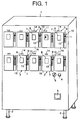
- the vending machine is provided with a box-shaped casing 1 which is set to independently stand on a floor or ground by means of four legs 2 arranged at four corners, respectively, at the bottom of the casing 1.
- the vending machine is further provided with a plurality of, ten(10) in the present embodiment, charge blocks 3 on the front surface of the casing 1 wherein it is arranged as five(5) charge blocks 3 on the upper row and the remaining five(5) charge blocks 3 on the lower row.
- the vending machine is still further provided with a coin inlet slot 4 at the front surface of the casing 1 and just below the lower row of the charge block 3 and on the right side and through which at least one coin is to be inserted into the casing 1, a coin return lever 5 arranged on the left side of the coin inlet slot 4 and a coin return port 6 arranged on the lower side of the coin inlet slot 4.
- a bank note inlet slot may be placed instead of or adding to the coin inlet slot 4.
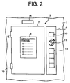
- Each of charge blocks 3 is constructed so that it is able to charge a secondary battery in a condition where it is attached to the phone body of the mobile phone. Furthermore, the charge block 3 is constructed to conform to a specification of a mobile phone and/or secondary battery. Accordingly, a notice board or plate 8 is attached to the front surface of each charge blocks 3 to explain what sort or kind and maker of the mobile phone can be charged by that block, as shown in Fig. 3. By looking at the notice board or plate 8, a mobile phone holder can find out the adaptable charge block 3 in which the mobile phone could be charged.
- each charge block 3 On the right side of a door 7 of each charge block 3, there is provided an operation panel 9 on which a block selection switch 10, a door open key 11, and four(4) charge time selection buttons 12, arranged vertically.
- the charge time selection buttons 12 are provided to set a charge time, which the mobile phone holder wishes.
- a charge lamp 14 indicating whether or not the block 3 is in a charging operation stand-by status, in a charging status, or in a charge completion status.
- the door 7 is swingably connected to the left edge of each charge block 3 through upper and lower hinges 15. Inside the door 7, a phone storage room 16 in which the mobile phone will be attached is arranged in the charge block 3. When the door 7 is opened, the phone storage room 16 will be exposed.
- the lock/unlock of the door 7 provided at the front opening 16a of the phone storage room 16 is accomplished by the key 11.
- the key 11 and a latch 13 which is provided to a central part of the side edge of the door 7 constitute a lock mechanism for locking/unlocking the door 7.
- a charge holder 17 On the bottom of the phone storage room 16, there is provided a charge holder 17 on which a mobile phone with the secondary battery to be charged will be placed. Where the mobile phone is placed to the charge holder 17, two charge terminals equipped to the bottom of the secondary battery is set to be contacted (or electrically connected) to two electrodes of the charge holder 17 which are arranged on the bottom thereof.
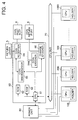
- the vending machine is provided with a main unit 50 for controlling the total operation of the machine and administrating the delivery and receipt of money, ten(10) charging units 100, 200, 300,....1000 corresponding to the ten(10) charging blocks 3, respectively, a power unit 60 for supplying an electric power to the main unit 50 and all of the charging units 100, 200, 300,....1000, and CPU bus 70 for electrically and mutually connecting the main unit 50 and the charging units 100, 200, 300,....1000.
- main unit 50 and the charging units 100, 200, 300,....1000 constitute a so-called master/slave relationship.
- each of the charging units 100, 200, 300,....1000 has both a standby mode and an active mode, wherein the charging units normally remain on standby mode.
- the standby mode the electric power is supplied to one part of the construction, thereby limiting the consumption of the electric power by the vending machine. If it is necessary to execute a charging operation, the mode of the charging units 100, 200, 300....1000 will be switched from the standby mode to the active mode under the control of the main unit 50.
- the charging units 100, 200, 300....1000 basically employ a common construction except for the shape of the holder to which the mobile phone is to be attached, position of the electrodes and a charging voltage, etc.
- the aforesaid main unit 50 includes a CPU (central processing unit) 51 for controlling the total operation of the vending machine and administrating the delivery and receipt of money, a ROM 52 for storing a control program to be executed by the CPU 51, a RAM 53 to be used as a working area for the control program which is executed in the CPU 51, a coin receptor 54 for temporarily receiving the coin which has been inserted through the coin inlet slot 4, a coin stocker 54a for stocking the coin, a coin discriminator 55 for discriminating a truth/false of the coin inserted through the coin inlet slot 4, and a change stocker 56 for stocking coins for change.
- a CPU central processing unit
- the coin temporally stocked in the coin receptor 54 will be returned to the coin return port 6 when it is discriminated as a false coin, and an unacceptable (for example, a foreign) coin, or when the return lever 5 has been operated. If it is necessary to make change, the change will be discharge to the coin return port 6.
- the charging unit 100 is constructed in such a manner that it received a command from the CPU 51 of the main unit 70 through the CPU bus 70 thereby executing the charging operation.
- the charging unit 100 is constructed to include a CPU 110 for controlling the operation thereof, a ROM 115 for storing a control program to be executed by the CPU 110, a RAM 120 to be used as a working area for the control program which is executed in the CPU 110, a timer 130 for setting the charging time, an interface (I/F) 140 for electrically connecting the CPU 110 with a peripherals as described later, a quick charger 150 for charging the secondary battery of the mobile phone by means of a constant current system, a holder 160 to which the mobile phone is to be attached, a unit switch (SW) 170 for propagating the selection result from the charging block selection switch 10 to the CPU 110 through the interface (I/F) 140, a key sensor 180 for propagating the sensing result about the lock/unlock operation by the key 11 to the CPU 110 through the interface (I/F) 140, a selection switch 190 for propagating the charging time selected by the charging time selection buttons 12 to the CPU 110 through the interface (I/F) 140 and the charging lamp 14 for
- the charging lamp 14 includes a green LED (light emitting device) 14G for emitting a green color light, yellow LED 14Y for emitting a yellow color light and a red LED 14R for emitting a red color light. These LEDs are set to light according to the transition of the charging operation.
- the holder 160 is provided with at least a positive (+) electrode 161 and a negative (-) electrode 162 which are set to be contacted or electrically connected to two terminals of the secondary battery of the mobile phone, respectively, when the mobile phone is attached to the holder 160.
- Ni-Cd nickel-cadmium
- Ni-MH nickel-metalhydride
- Li-ION lithium-ion
- operational or discharge voltages of the mobile phone such as 3.0 (V), 3.6 (V), 6.0 (V), and 7.2 (V), etc.
- the secondary battery is attached to the mobile phone in a form of a battery package with 3.6(V) where three(3) Ni-Cd battery cells, a nominal voltage of each of which is set to be 1.2 (v), are connected in a series; or a battery package with 3.6 (V) where a single Li-ION battery cell, a nominal voltage of which is set to be 3.6 (V), is connected; or a battery package with 7.2 (V) where two(2) Li-ION battery cells are connected in a series.
- a protection circuit is usually provided so that the charging voltage thereof is set to be relatively high, for example, 5.5 (V) even though the discharge voltage thereof is set to be 3.6 (V).
- positions of the electrodes 161 and 162, the shape of each of the electrodes 161 and 162 are uniquely defined according to a specification of the mobile phone, the type of the secondary battery of the mobile phone.
- the position and shape of the electrodes in the holder 160 and the charging voltage and the charging current in the quick charger 150 are set to conform to the specification of the secondary battery or the battery package attached to the specific mobile phone. Accordingly, the position and shape of the electrodes and the charging voltage and current are different for each charging units, however, the electric construction and the charging system of the quick charger 150 is common to the other quick charger.
- the quick charger 150 is constructed so as to execute charging control with the constant current system.
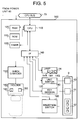
- the quick charger 150 includes a control circuit 151 for controlling the charging operation, an interface (I/F) 152 for inputting and outputting control signals for communicating between the control circuit 151 and the CPU 110, a constant current charging circuit 153 for charging the secondary battery with the constant current, a voltmeter 154 for measuring the terminal voltage (V) of the secondary battery, a differentiation circuit (DIFF) 155 for measuring a change rate in time (dV/dt) of the terminal voltage, a register (REG) 156 in which a threshold value (TH) to be utilized to compare the change rate in time (dV/dt) is set and stored, and a comparator (COMP) 157 for comparing the change rate in time (dV/dt) with the threshold value (TH).
- a control circuit 151 for controlling the charging operation
- an interface (I/F) 152 for inputting and outputting control signals for communicating between the control circuit 151 and the CPU 110
- a constant current charging circuit 153 for charging the secondary battery with the constant current
- V
- a reference numeral 158 indicates the secondary battery to be charged
- a reference character CMD denotes a charging start command signal from the CPU 110
- STR shows a charging start notification signal to the CPU 110
- CMP designates a charging completion signal to CPU 110.
- TMR timer signal
- Fig. 7 shows a flowchart of the summary of the operation of the vending machine in view of an operation of the mobile phone holder, basically.
- the mobile phone holder inserts a coin through the coin inlet slot 4 in a step S10, and search for the charging block 3 suitable for charging the secondary battery of the mobile phone he or she possesses. Then, the mobile phone holder depresses the charging block selection switch 10 of the charging block 3, which he or she desires, from all switches 10 in a step S15.
- the mobile phone holder opens the door 7 of the corresponding charging block 3 in a step S20, attaches the mobile phone to the charging holder 17 of the corresponding charging block 3 in a step S25, and depresses a charging time selection button 12, which corresponds to the charging time he or she desires and which is allowed in view of amount of money of the coin inserted through the slot 4 in a step S30.
- the mobile phone holder closes the door 7 and then locks the door 7 by key 11 in a step S35.
- the charging operation is started in a step S40. Note that if the mobile phone holder temporally leaves the vending machine during the charging operation, the key 11 may be taken along.
- a calculation of a change is executed in a step S50, based on an amount of money of the coin which has been inserted through the slot 4 and the charging time selected by the selection switches 12 while the charging operation is started concurrently in the step S40.
- the detail of the change calculation will be described with reference to Fig. 9
- a term for calculation of the change is shorter than that for the charging operation. Accordingly, if it is determined that there is no change in a step S55 after the change calculation, the process will go to a step S45 to detect whether or not the charging operation is to be halted or completed. On the other hand, if it is determined that there is a change in the step S55, the process will go to a step 60 to make change and discharge the change to the coin return port 6, and go to the step S45, and then wait for the completion of the charging operation in the step S40.
- step S45 when it is determined that the charging operation is completed or halted, the process will go to a step S65 for insertion of the key 11 and unlocking of the door 7. Then, the door 7 is opened in a step S70 and finally the mobile phone with the secondary battery of which the charging operation is completed is detached from the holder 17 in a step S75.
- Fig. 8 is a flowchart for showing the operation of the main unit 50 of the vending machine
- Fig. 9 is a flowchart for describing the operation of the change
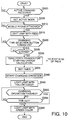
- Fig. 10 is a flowchart for showing the charging operation in the charging unit.
- the main unit 50 at first, it is waited for inserting the coin in a step S100 as shown in Fig. 8. If it is determined that the coin is inserted through the coin inlet slot 4, it is determined that whether the coin is true or false by the coin discriminator 55 in a step S105. When it is determined that the coin is true in the step S105, the process will go to a step S110. On the other hand, when it is determined that the coin is false or unacceptable in the step S105, the process will go to a step S115 to return the coin to the coin return port 6 and then return to the step S100.
- the amount of money (M) which has been inserted through the slot 4 is calculated.
- certain lamps, which correspond to the amount of money of the inserted coin(s), among all lamps which are provided for all the charging time selection buttons 12 are turned on in a step S120.
- the four(4) selection buttons 12 correspond to 5, 10, 15 and 30 minutes, respectively, and these four(4) charging time charges correspond to 50, 100, 150, 300 yens, respectively. If one coin for 50 yens is inserted, the lamp corresponding to 5 minutes is only turned on among all the lamps, while if 150 yens are inserted, the lamps corresponding to 5, 10 and 15 minutes are turned on among all the lamps.
- step S120 After the step S120, it is detected that whether or not the return lever 5 is operated in a step S125. If it is determined that the return lever 5 is operated in the step S125, the process will return to the step S115 to return the coin to the return port 6. On the other hand, if it is determined that the return lever 5 is not operated in the step S125, the process will go to a step S130.
- step S130 it is detected whether or not anyone of the charging block selection switches 10 is depressed. If it is determined that none of the switches 10 is depressed in the step S130, the process will return to the step S125. On the other hand, if it is determined that one of the switches 10 is depressed in the step S130, the process will go to a step S135 to detect that which is the charging block 3 where the selection switch 10 is depressed. Then, the charging unit 100 of the charging block 3 detected in the step S130 is caused to be activated, that is, set in the active mode in a step S140.
- the charging operation is executed in the charging unit 100 in the active mode in a step S145.
- the detail of the charging operation will be described later with reference to Fig. 10.
- step S145 After the step S145, it is waited that a start trigger signal for the change calculation, which will be described later in detail, is received in a step S150. If it is determined that the start trigger signal is received in the step S150, the process will go to a step S155 to execute the change calculation and the change discharge.
- the process will go to a step S215 to determine that there is no change and then return to the main routine shown in Fig. 8.
- the difference between M and Mo is defined as a change and make change or discharge the change from the change stocker 56 to the coin return port 6 in a step S220 and then the process will return to the main routine shown in Fig. 8.
- step S160 it is waited that the door 7 is unlocked in a step S160. More specifically, in the step S160, it is waited for receiving a door open signal from the charging unit 100 now on use in the CPU 51. If it is determined that the door 7 is unlocked in the step S160, the process will go to a step S165 to return the mode of the charging unit 100, the door 7 of which is unlocked, from the active mode to the stand-by mode. In this time, the charging lamp 14 is turned off.
- the main unit 50 can execute the processes of the steps S135 to S165 for a plurality of charging units 100 (200, 300,....1000) in parallel.
- the charging unit 100 is set to be usually in the stand-by mode as mentioned above and waiting for receiving the active command from the CPU 51 of the main unit 50.
- step S300 it waits to receive the active command from the CPU 51 in a step S300.
- the process will go to a step S305 to cause the charging unit 100 be in the active mode. Accordingly, the electric power is supplied to each component of the charging unit 100 thereby being enable condition (status) for charging operation.
- step S310 it waits for the mobile phone to be attached to the holder 160 in a step S310.
- the process will go to a step S315 to turn on the red LED 14R of the charge lamp 14. Accordingly, the mobile phone holder is informed that the preparation of the charging operation is completed.
- step S320 it waits for anyone of the charging time selection buttons 12 to be depressed in a step S320.
- the process will go to a step S325 to wait that the door 7 is locked by the key 11.
- the key sensor 180 detects this lock and the process will go to a step S330 to send forth the start trigger signal for the change calculation to the CPU 51 of the main unit 50. Accordingly, it starts to calculate the change in the main unit 50, as indicated in the step S155 shown in Fig. 8.
- the charging time is set in accordance with the selection by the selection button 12 in a step S335.
- the charging operation is started by the quick charger 150 in a step S340.
- the charging lamp 14 is switched from the lighting of the red LED 14R to the lighting of the yellow LED 14Y in a step S345. Accordingly, it informs the mobile phone holder that the charging operation is now being executed or the secondary battery is now being charged.
- step S360 The charging lamp 14 is switched from the lighting of the yellow LED 14Y to the lighting of the green LED 14G in the step S360. Accordingly, it informs the mobile phone holder that the charging operation for the secondary battery of the mobile phone is halted or completed.
- Figs. 11A and 11B show a table and a graph, respectively, each for indicating the charging characteristics of the alkali-secondary battery such as Ni-Cd or Ni-MH battery with a nominal voltage of 1.2 (V). Note that these figures are shown in Japanese Patent Publication Laid-Open No. 7-312229.
- the battery voltage (that is, terminal voltage) will be suddenly raised up from a termination voltage (about 1.2 to 1.3 (V)) around a region near substantially 0% of a charged electricity amount according to the elapse of the charging time.
- the charged electricity amount will increase according to the elapse of the charging time and then the change rate in time of the battery voltage will be decreased.
- the change rate in time of the battery voltage will be substantially zero(0) around a region near substantially 60% of the charged electricity amount.
- the battery voltage of the secondary battery will increase again according to the further increase of the charged electricity amount.
- the battery voltage will saturate at a predetermined value when the charged electricity amount exceeds 100% and then decrease a little. It should be noted that it will require about 35 minutes for 60% charging condition (that is, 60% of the charged electricity amount).
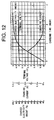
- Fig. 12 indicates the charging characteristics of the Li-ION secondary battery with a nominal voltage of 3.6 (V) where it is charged by a constant current/constant voltage charging system, disclosed by NIKKEI ELECTRONICS , on page 108, issued on November 28, 1995.
- the battery voltage will be suddenly raised up from a termination voltage (for example, about 2.5 to 3.2 (V)) around a region near substantially 0% of a charged electricity amount according to the elapse of the charging time.
- the charged electricity amount will increase according to the elapse of the charging time and then the change rate in time of the battery voltage will be decreased.
- the charged electricity amount will reach about 60% at a timing when the charging system is switched from the constant current system to the constant voltage system, that is, the terminal voltage of the secondary battery reaches the predetermined charged voltage (for example, about 4.1 to 4.2 (V)) and the change rate in time of the terminal voltage becomes to be very small (or near to zero(0)) It should be noted that it will require about 36 minutes for 60% charging condition (that is, 60% of the charged electricity amount).
- the predetermined charged voltage for example, about 4.1 to 4.2 (V)
- the construction of the charging circuit would be advantageously simpler than that of a conventional one.
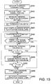
- the control circuit 151 receives the charging start command signal (CMD) from the CPU 110 through the interface (I/F) 152 in a step S400 and then receives the timer signal (TMR), the value of which is set to "1", that is, a timer-on(TMR-ON) signal, from the CPU 110 in a step S405.
- CMD charging start command signal
- I/F interface
- TMR timer signal
- the terminal voltage of the secondary battery which is attached to the holder 160 is measured as an initial value in a step S410 and then the threshold value (TH) is set to the register (REG) in a step S415.
- the threshold value (TH) is very small, near zero(0), and stored in ROM of the control circuit 151 with considering to the sort of the secondary battery which is capable of being charged by the quick charger 150 and its charging characteristics.
- the charging voltage (Vo) of the secondary battery is also stored in the ROM.
- the control circuit 151 sends forth the charging start notification signal (STR) to the CPU 110 in a step S420. Note that the CPU 110 controls the yellow LED 14Y of the charging lamp 14 to be turned on for indicating that it is executing the charging operation, upon receiving the signal (STR).
- the control circuit 151 then controls the constant current charging circuit 153 to start the charging of the secondary battery with the constant current in a step S425.
- a following step S430 it is detected that whether or not the timer signal (TMR), the value of which is set to "0", that is, timer-off (TMR-OFF) signal, is received from the CPU 110.
- TMR timer signal
- TMR-OFF timer-off
- the process will go to a step S455 to halt or complete the charging operation.
- the process will go to a step S435
- the terminal voltage (V) of the secondary battery is measured by means of the voltmeter 154. Then, it is determined whether or not the measured terminal voltage (V) exceeds a charged voltage (Vo) defined for the secondary battery in a step S440. When it is determined that the measured terminal voltage (V) is larger than the charged voltage (Vo), that is, V>Vo in the step S440, the process will go to the step S455 to halt the charging operation.
- step S445 a change rate in time (dV/dt) of the terminal voltage (V) is measured by means of the differentiation circuit (DIFF) 155. Then, the comparator (COMP) 157 compares the change rate in time (dV/dt) with the threshold value (TH) set in the register (REG) 156 in a step S450.
- step S450 If it is determined that the change rate in time (dV/dt) is larger than the threshold value (TH) in the step S450, the process will return to the step S425 to continue the charging operation since the terminal voltage (V) still continues to raise up and the charged electricity amount has not reached the 60% point.
- step S450 If it is determined that the change rate in time (dV/dt) is equal to or smaller than the threshold value (TH) in the step S450, the process will go to the step S455 to halt the charging operation in the constant current charging circuit 153 since the terminal voltage (V) stops to raise up and the charged electricity amount has reached 60%.
- control circuit 151 sends forth the charging completion signal (CMP) to the CPU 110 to complete the charging operation in a step S460.
- CMP charging completion signal
- vending machine according to the present invention may be placed in any public places, such as station precincts, underground markets, hotels, and shopping centers, etc.
- the mobile phone holder can charge the secondary battery outdoors, using the vending machine of the present invention installed in public places.
- the construction of the charging circuit can be advantageously simpler than that of a conventional one.
- the charging operation may be halted when it is determined that the charged electricity amount of the secondary battery has reached about 60% by monitoring the accumulated charged energy from the terminal voltage (V) of the secondary battery now on charged, the change rate in time (dV/dt) of the terminal voltage (V), the charging current in the constant current charging circuit 153 and the charging time, wherein if the secondary battery to be charged is a type in which the terminal voltage will fall to the termination voltage when the secondary battery is completely consumed or discharged by 100%.
- the positions and shape of the electrodes of the holder 160, the charging voltage and charging current in the quick charger 150 are conforming to the specification of the secondary battery or battery package equipped to the specific mobile phone. Accordingly, it is possible to experimentally determine the relationship between the charged voltage and the charged electricity amount by obtaining the charging characteristics of the secondary battery or battery package to be equipped to the mobile phone by an experimental method. If it is possible to experimentally obtain the relationship between the charged voltage and the charged electricity amount, the charging operation may be halted when it is determined that the terminal voltage reaches a predetermined value which is set to be lower than the maximum charged voltage defined for the secondary battery by only detecting or monitoring the terminal voltage of the secondary battery. In this case, it is preferred to halt the charging operation when it is determined that the terminal voltage measured by the voltmeter reaches approximately 60% to 90% of the maximum charged voltage defined for the secondary battery.
- the mobile phone holder can charge the secondary battery which has been completely or partially consumed such that it is unusable, by using the vending machine of the present invention, placed in public spaces in a short time or easily, even though it is not charged 100%. It is possible to urgently use the mobile phone even though the secondary battery has not been fully or 100% charged, in a condition where the mobile phone holder does not have a replacement secondary battery.
- the present invention has an advantage that the mobile phone holder can lightheartedly use the mobile phone or charge the discharged secondary battery without possessing a replacement secondary battery, using the vending machine according to the present invention, settled in many places such as public places.
- the quick charger employs a constant current charging system
- the present invention is not limited to employ such a constant current charging system but may employ a variable current charging system wherein a magnitude of the charging current is increased according to a charging time elapses in order to avoid a bad influence to the secondary battery by the quick charging operation.
- the magnitude of the charging current is applied to the secondary battery in an initial stage of the charging operation, then is gradually raised up in a mid stage thereof, and raised up to a high value in a final stage thereof.
- the vending machine should correspond to many types of mobile phones or secondary batteries. According to the present invention, it is very advantageous to the vending machine because the basic design of the quick charger can be standardized over different types of secondary batteries, thereby contributing to reduce a manufacturing and/or developing cost of the vending machine.
- the vending machine is provided for charging the mobile phone.
- the present invention is not limited to such an application but may charge the secondary battery for other portable electric devices, such as an electric notebook, a laptop-type personal computer and a portable facsimile device, etc.
- the door 7 is locked/unlocked by means of the key 11.
- the present invention is not limited to such a construction but may lock/unlock the door 7 by means of an electric key as described later as one modification of the preferred embodiment.
- Fig. 14 is a front view of a charging block of one modification of the vending machine of the aforesaid embodiment according to the present invention wherein an electric lock system including a ten-key keyboard is applied to the door 7.
- a ten-key operational section 27 is provided instead of the key 11 in the aforesaid embodiment.
- a correction key (C) 29 arranged to the ten-key operational section 27 is provided for correcting a secret code input by using numeral keys 28.
- the input error to the secret code is corrected and the operator can input the secret code again.
- the secret code of four digits is input through the numeral keys 28.
- the input key (IN) 30 is depressed after input of the secret code, the secret code is registered in the control circuit and at the same time the door 7 is electrically locked and the charging operation to the secondary battery of the mobile phone is started.
- the operator After a completion of the charging operation, the operator must input the secret code, which has been already registered, through the numeral keys 28.
- the door 7 is unlocked when the input secret code coincides with the registered secret code, thereby accessing the mobile phone with the secondary battery just charged from the vending machine, while the door 7 is opened.
- the vending machine may equip a printer in front of the casing 1, for printing the secret code which the operator registered through the ten-key operational section 27.
- the printer is equipped to the vending machine, it is possible to avoid an inconvenience where the operator forgets the secret code.
- the necessities to install the vending machine for charging the secondary battery of the mobile phone are widely different from each other according to the installation sites. That is to say, it would be strongly necessary to install a lot of vending machines each for charging the secondary battery of a plurality of mobile phones or a large capacity to a place where many mobile phone holders concentrate. On the other hand, it would be sufficient to install at least one vending machine with small capacity to a place where a small number of mobile phone holders gather. Furthermore, the needs for installing a vending machine even to the same place will change as a time passes.
- Fig. 15 is a perspective view showing a vending system for charging a secondary battery of a mobile phone of the present embodiment. In Fig. 15, it is shown that the vending system includes two maximum configuration sets.
- the vending system of the present embodiment includes at least one charging set each composed of a basic control unit 1100 for performing control of supplying electric power, a total construction of the system, administrating the communication between a system user and the system, and four(4) extension charging units 1200, 1300, 1400 and 1500 at most.
- Each of the extension charging units 1200, 1300. 1400 and 1500 can accommodate four(4) mobile phones into different compartments, respectively, and charge the secondary battery of the accommodated mobile phone.
- the single charging set of the vending system includes a basic control unit and at least one extension charging unit.
- the minimum configuration of the charging set includes a basic control unit 1100 and a single extension charging unit 1200.
- the other extension charging units 1300, 1400, 1500 can be further added or connected to the extension charging unit 1200 which has already been included, while combination of the basic control unit 1100 and four(4) extension charging units 1200, 1300, 1400 and 1500 constitute the maximum configuration of the charging set.
- the maximum configuration of the charging set has a charging capability to charge up sixteen(16) mobile phones.
- the maximum configuration of the charging set can be added or connected to the other charging set including the maximum configuration, with separators 1660 sandwiched therebetween as shown in Fig. 15. Namely, a plurality of charging sets are arbitrary connected to each other and installed while the adjacent ones are mechanically coupled through the separators 1600.
- the upper portions of the extension charging units 1200 and 1400 are mechanically connected through the pair of metal fixtures 1270 and 1280, with both legs of the metal fixture 1270 being inserted into an opening 1210 formed to the upper surface of the unit 1200 and an opening 1410 formed to the upper surface of the unit 1400, respectively, while both legs of the metal fixture 1280 being inserted into an opening 1220 formed to the upper surface of the unit 1200 and an opening 1420 formed to the upper surface of the unit 1400, respectively.
- both legs of the metal fixture 1270 being inserted into an opening 1210 formed to the upper surface of the unit 1200 and an opening 1410 formed to the upper surface of the unit 1400, respectively
- both legs of the metal fixture 1280 being inserted into an opening 1220 formed to the upper surface of the unit 1200 and an opening 1420 formed to the upper surface of the unit 1400, respectively.
- the lower portions of the extension charging units 1200 and 1400 are mechanically connected through the pair of metal fixtures 1250 and 1260, with both legs of the metal fixture 1250 being inserted into an opening 1230 formed to the under surface of the unit 1200 and an opening 1430 formed to the under surface of the unit 1400, respectively, while both legs of the metal fixture 1260 being inserted into an opening 1240 formed to the under surface of the unit 1200 and an opening 1440 formed to the under surface of the unit 1400, respectively.
- the reference numerals 1450 and 1460 indicate U-shaped connector for extension of the charging set.
- the basic control 1100 includes a LCD (liquid crystal display) 1101 for displaying a message or guidance for operating the system, a ten-key 1102 through which a variety of instructions relating the charging operation are input, a printer 1103 for outputting the system user a necessary information to draw or detach the mobile phone with charged secondary battery from the system after the charging operation, a coin inlet slot 4, a coin return lever 5 and a coin return port 6. It should be noted that it is possible to provide a banknote inlet slot (not shown) in order to receive a banknote.
- Each of the extension charging units 1200, 1300, 1400 and 1500 is constructed so as to accommodate a mobile phone and to be able to charge the secondary battery of the mobile phone, which has an interchangeability with respect to the charging system, among mobile phones which are put on the market. Accordingly, on the door 7 which is provided to the front of each of the compartments of the extension charging units, there is attached a notice board or plate 8 on which a plurality of compatible mobile phone names are described. By looking the notice board or plate 8, the system user or mobile phone holder can find the suitable compartment in which his or her secondary battery can be charged.
- a mobile phone holder or charge holder (not shown) to which the mobile phone with empty secondary battery to be charged is attached.
- the secondary battery of the mobile phone has two electrodes on the bottom thereof and the charge holder has two terminals on the upper surface thereof, and the electrodes are set to be contacted or electrically connected to two terminals, respectively, when the mobile phone is attached to the charge holder.
- the door 7 of each of the compartments of the extension charging units is set to be locked/unlocked by means of an electric lock system under control from the basic control unit 1100.
- a charge lamp 1201 for indicating any of a charging operation stand-by status, a charging status, or a charge completion status.
- a label 1202 on which a discrimination number for specifying the compartment is described.
- the charging lamp 1201 includes a green LED for emitting a green color light, a yellow LED for emitting a yellow color light and a red LED for emitting a red color light. These LEDs are set according to the transition of the charging operation. That is, the green LED is turned on when the charge completion is indicated, the yellow LED is turned on when the charging is indicated and the red LED is turned on when the charging operation stand-by is indicated.
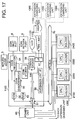
- Fig. 17 is a block diagram for showing the structure of the vending system of the present embodiment, in which like reference numerals or characters designate the same or similar parts throughout the figures thereof.
- the vending system is provided with the basic control unit 1100, four(4) extension charging units 1200, 1300, 1400 and 1500 each having a compartment 2100, 2200, 2300 and 2400 and a power unit 60 for supplying an electric power to the basic control unit 1100 and extension charging units 1200, 1300, 1400 and 1500.
- the basic control unit 1100 and the extension charging unit 1200 are electrically and mutually connected with each other by means of a CPU bus 70 and the basic control unit 1100 and the remaining extension charging units 1300, 1400 and 1500 are electrically and mutually connected by means of an extension unit interface (I/F) 58. Accordingly, it is unnecessary to include the extension unit interface (I/F) 58 where the system is constituted by the minimum configuration, that is, includes the extension charging unit 1200 solely. In other words, it is necessary to add the extension unit interface (I/F) if the extension charging unit or units 1300, 1400 and 1500 are additionally connected to the extension charging unit 1200.
- the CPU 51 provided to the basic control unit 1100 is constructed to perform control the lock/unlock of the door 7 of each of the compartments of the extension charging units 1200, 1300, 1400 and 1500 electrically.
- basic control unit 1100 and the extension charging units 1200, 1300, 1400 and 1500 constitute a so-called master/slave relationship.
- each of the extension charging units 1200, 1300, 1400 and 1500 has both of standby mode and active mode, wherein the extension charging units normally remain on standby mode.
- the standby mode the electric power is supplied to one part of the unit, thereby restraining the consumption of the electric power. If it is necessary to execute the charging operation, the mode of the extension charging units 1200, 1300, 1400 and 1500 will be switched from the standby mode to the active mode under the control of the basic control unit 1100.
- the basic control unit 1100 includes an interface (I/F) 57 for connecting with the LCD 1101, the ten-key 1102 and the printer 1103 with CPU 51 as well as the extension unit interface (I/F) 58.
- I/F interface
- I/F extension unit interface
- Fig. 18 is a flowchart showing the charging operation in the vending system of the present embodiment, in which like reference numerals or characters designate the same or similar steps throughout the figures thereof.
- the guidance for using the vending system is displayed and indicated on the LCD 1101 in a step S12.
- the system user or the mobile phone holder searches a compartment suitable for charging the secondary battery of the mobile phone he or she possesses, among all compartments.
- the mobile phone holder inputs the discrimination number, corresponding to the compartment he or she finds, through the ten-key 1102 in a step S16.
- the mobile phone holder depresses "#" key in the ten-key 1101 after the input of the discrimination number in order to inform the CPU 51 the completion of the input operation.
- the CPU 51 controls the door 7 to unlock electrically in a step S17. Thereafter, The mobile phone holder opens a door 7 of the corresponding compartment in a step S20, attaches the mobile phone to the charge holder 17 of the corresponding compartment in a step S25, and closes the door 7. If the mobile phone is correctly attached to the charge holder, the red LED is turned on in the charging lamp 1201.
- the mobile phone holder then inputs a charging time (for example, 5, 10, 15 or 30 minutes) which he or she desires and which is allowed in view of amount of money of the coin inserted through the slot 4, by means of the ten-key 1102, according to the guidance of the LCD 1101 and then inputs a secret code of four(4) digits in a step S31. For example, if the mobile phone holder wishes to input "30 minutes” as a charging time and "1234" as a secret code, he or she inputs "30*" and then "1234#" from the ten-key 1101.
- a charging time for example, 5, 10, 15 or 30 minutes
- the door 7 is then automatically locked by key 11 in a step S36.
- the charging operation is started in a step S40. Note that the yellow LED is turned on in the charging lamp 1201 during the charging operation.
- the printer 1103 prints out the discrimination number and the secret code for unlocking the door 7 in a step 49 while the charging operation is started in the step S40 concurrently.
- step S49 a calculation of change is executed in a step S50, based on an amount of money in a coin which has been inserted through the slot 4 and the charging time selected in the step 31
- a term for calculation of the change is usually shorter than that for the charging operation. Accordingly, if it is determined that there is no change in a step S55 after the change calculation, the process will go to a step S45 to detect whether or not the charging operation is halted or completed. On the other hand, if it is determined that there is a change in the step S55, the process will go to a step 60 to make change and discharge the change to the coin return port 6, and go to the step S45, and then wait for the completion of the charging operation in the step S40.
- step S45 when it is determined that the charging operation is completed or halted, the green LED is turned on in the charging lamp 1201 and the process will go to a step S66.
- step S66 the mobile phone holder inputs the discrimination number for indicating the compartment now on use and the secret code of four(4) digits for unlocking the door 7 by means of the ten-key 1102.
- the door 7 is unlocked electrically under the control of the CPU 51. Then, the door 7 is opened in a step S70 and finally the mobile phone with the secondary battery of which the charging operation is completed is detached from the charge holder in a step S75.
- a vending system which can flexibly correspond to the needs for settle the vending machine and adjust the charging capability thereof due to add or reduce the extension charging unit or units.
- each of the extension charging units can charge four(4) secondary batteries concurrently and each of the charging sets can equip four(4) extension charging units, accordingly can charge sixteen(16) secondary batteries concurrently, however, the present invention is not limited to such a number, but the extension charging unit is possible to charge five(5) or more secondary batteries by including more compartments and the charging set is possible to include five(5) or more extension charging units.
- the secret code is set by the system user or mobile phone holder, however, the present invention is not limited to such a construction but it is possible to issue a secret code from the vending system, printing the secret code by the printer 1103.
- the charging block or the compartment is at room temperature
- the present invention is not limited to such a construction but it is possible to equip an air conditioner in the machine or the unit for controlling the temperature in the charging block or the compartment to a constant temperature in view of the discharge characteristics of the secondary battery depending on the temperature thereof.
- the door 7 of each of the charging blocks or compartments is provided with the lock mechanism mechanically or electrically
- the present invention is not limited to such a construction but it is possible to eliminate the lock mechanism from the door 7 if the installation site of the vending machine is safe.
- the charging operation will be executed during a charging time which conforms to the amount of money of the inserted coin
- the present invention is not limited to such a construction but it is possible to charge the secondary battery during a charging time which is set by the mobile phone holder and clear off the deficit if it exists when the mobile phone is detached from the vending machine after the completion of the charging operation.
Landscapes
- Physics & Mathematics (AREA)
- General Physics & Mathematics (AREA)
- Business, Economics & Management (AREA)
- Engineering & Computer Science (AREA)
- Accounting & Taxation (AREA)
- General Business, Economics & Management (AREA)
- Strategic Management (AREA)
- Finance (AREA)
- Theoretical Computer Science (AREA)
- Power Engineering (AREA)
- Signal Processing (AREA)
- Charge And Discharge Circuits For Batteries Or The Like (AREA)
- Beverage Vending Machines With Cups, And Gas Or Electricity Vending Machines (AREA)
- Secondary Cells (AREA)
Applications Claiming Priority (9)
| Application Number | Priority Date | Filing Date | Title |
|---|---|---|---|
| JP317044/95 | 1995-11-13 | ||
| JP7317044A JPH10116388A (ja) | 1995-11-13 | 1995-11-13 | 携帯電話機用充電電力自動販売機 |
| JP31704495 | 1995-11-13 | ||
| JP8294080A JPH10143758A (ja) | 1996-11-06 | 1996-11-06 | 携帯電話機用充電電力自動販売システム |
| JP294080/96 | 1996-11-06 | ||
| JP29408196 | 1996-11-06 | ||
| JP294081/96 | 1996-11-06 | ||
| JP29408096 | 1996-11-06 | ||
| JP8294081A JPH10145982A (ja) | 1996-11-06 | 1996-11-06 | 充電装置 |
Publications (2)
| Publication Number | Publication Date |
|---|---|
| EP0773519A2 true EP0773519A2 (fr) | 1997-05-14 |
| EP0773519A3 EP0773519A3 (fr) | 1999-08-11 |
Family
ID=27337874
Family Applications (1)
| Application Number | Title | Priority Date | Filing Date |
|---|---|---|---|
| EP96118202A Withdrawn EP0773519A3 (fr) | 1995-11-13 | 1996-11-13 | Machine de vente pour charger une batterie secondaire d'un mobilophone |
Country Status (7)
| Country | Link |
|---|---|
| EP (1) | EP0773519A3 (fr) |
| KR (1) | KR100244589B1 (fr) |
| CN (1) | CN1166071A (fr) |
| AU (1) | AU698555B2 (fr) |
| CA (1) | CA2190049C (fr) |
| SG (3) | SG60198A1 (fr) |
| TW (1) | TW314619B (fr) |
Cited By (18)
| Publication number | Priority date | Publication date | Assignee | Title |
|---|---|---|---|---|
| FR2766950A1 (fr) * | 1997-07-30 | 1999-02-05 | Herve Borgoltz | Dispositif de livraison d'energie electrique |
| EP0905962A1 (fr) * | 1997-09-30 | 1999-03-31 | Vittoria A.V.V. | Poste automatique de service pour téléphones mobiles |
| GB2344680A (en) * | 1998-12-11 | 2000-06-14 | Morris Alphonso Stewart | Pay operated multiple battery pack charger |
| GB2345595A (en) * | 1999-01-08 | 2000-07-12 | Steven Artus | Multiple charger for mobile phones |
| FR2838015A1 (fr) * | 2002-03-26 | 2003-10-03 | Moustafa Merouan | Borne de recharge pour telephone portable |
| WO2003085800A1 (fr) * | 2002-04-08 | 2003-10-16 | Alps Electric Co., Ltd. | Appareil de chargement par alimentation dielectrique sans contact |
| US6756765B2 (en) * | 2002-10-08 | 2004-06-29 | Koninklijke Philips Electronics N.V. | System and method for charging users to recharge power supplies in portable devices |
| GB2400989A (en) * | 2003-03-11 | 2004-10-27 | Ryan Alexander Mcdonald | A coin operated mobile phone recharging unit |
| GB2427970A (en) * | 2005-07-02 | 2007-01-10 | Stanley Ernest Harper | A cabinet for the recharging of a plurality of electrical batteries |
| GB2428525A (en) * | 2005-07-20 | 2007-01-31 | Peter Denness | A battery charging cabinet |
| ES2317771A1 (es) * | 2007-01-09 | 2009-04-16 | Elias Jose Martin Montes | Organizador de cargadores. |
| EP2101390A2 (fr) | 2008-03-14 | 2009-09-16 | Chargee Sp. z o.o. | Dispositif et procédé pour charger des batteries et de dispositifs électroniques portable en libre-service |
| US7996238B2 (en) * | 2005-06-17 | 2011-08-09 | Ntt Docomo, Inc. | Power transmitting device, power receiving device, authentication/billing proxy device, electrical charging system, power transmitting method, power receiving method and electrical charging method |
| EP2428939A1 (fr) * | 2010-09-08 | 2012-03-14 | Siemens Aktiengesellschaft | Automate de service destiné au revêtement et/ou au chargement d'un accumulateur d'énergie pour un vélo électrique |
| GB2507712A (en) * | 2012-08-17 | 2014-05-14 | Anthony Martin | Charging device for mobile phone |
| WO2015167476A1 (fr) * | 2014-04-29 | 2015-11-05 | Powerit, Inc. | Dispositif et système pour charger des dispositifs électroniques mobiles |
| EP3258566A4 (fr) * | 2015-02-12 | 2018-08-01 | Shenzhen Laidian Technology Co., Ltd. | Terminal de location d'alimentation électrique mobile |
| CN114511966A (zh) * | 2022-02-15 | 2022-05-17 | 山西恒运售电有限公司 | 一种户外高压分体式售电装置 |
Families Citing this family (4)
| Publication number | Priority date | Publication date | Assignee | Title |
|---|---|---|---|---|
| JP2009217251A (ja) * | 2008-02-12 | 2009-09-24 | Nec Lcd Technologies Ltd | 閲覧端末、充電用端末、及びこれらを利用した通信システム、送受信システム |
| CN103646470B (zh) * | 2013-12-16 | 2016-06-29 | 深圳市拓特电子有限公司 | 充电器租售机 |
| CN110171314B (zh) * | 2019-05-14 | 2020-05-12 | 温州市阳安电子科技有限公司 | 一种充取一体式智能充电柜 |
| KR102721841B1 (ko) * | 2022-10-19 | 2024-10-25 | 이박스 주식회사 | 매립형 콘센트 에너지 충전 스테이션 시스템 및 제어 방법 |
Family Cites Families (8)
| Publication number | Priority date | Publication date | Assignee | Title |
|---|---|---|---|---|
| US3870135A (en) * | 1971-03-17 | 1975-03-11 | Carton Sales Inc | Cigarette carton dispensing system |
| JPS53127000A (en) * | 1977-04-12 | 1978-11-06 | Matsushita Electric Ind Co Ltd | Automatic vending machine of storage batteries |
| US4951308A (en) * | 1988-12-29 | 1990-08-21 | Cellular Communications Corporation | Automated vending of cellular hand-held telephones and cellular telephone services |
| JP2726942B2 (ja) * | 1989-07-10 | 1998-03-11 | 日本電信電話株式会社 | 2次電池の自動販売機とその管理方法 |
| DE4134410C2 (de) * | 1991-10-02 | 1994-10-20 | Accumulata Verwaltungs Gmbh | Verkaufssystem |
| JPH06315233A (ja) * | 1993-04-28 | 1994-11-08 | Fujitsu Ltd | 電池の充電制御方法 |
| US5631536A (en) * | 1994-05-16 | 1997-05-20 | Tseng; Ling-Yuan | Rechargeable battery vending apparatus |
| US5544784A (en) * | 1995-05-26 | 1996-08-13 | Motorola, Inc. | Rechargeable battery vending machine |
-
1996
- 1996-11-12 CA CA002190049A patent/CA2190049C/fr not_active Expired - Fee Related
- 1996-11-12 AU AU71724/96A patent/AU698555B2/en not_active Ceased
- 1996-11-12 KR KR1019960053556A patent/KR100244589B1/ko not_active Expired - Fee Related
- 1996-11-12 CN CN96114558A patent/CN1166071A/zh active Pending
- 1996-11-13 SG SG1998000307A patent/SG60198A1/en unknown
- 1996-11-13 TW TW085113812A patent/TW314619B/zh active
- 1996-11-13 SG SG1998000299A patent/SG60197A1/en unknown
- 1996-11-13 EP EP96118202A patent/EP0773519A3/fr not_active Withdrawn
- 1996-11-13 SG SG1996011117A patent/SG49986A1/en unknown
Non-Patent Citations (1)
| Title |
|---|
| None |
Cited By (22)
| Publication number | Priority date | Publication date | Assignee | Title |
|---|---|---|---|---|
| FR2766950A1 (fr) * | 1997-07-30 | 1999-02-05 | Herve Borgoltz | Dispositif de livraison d'energie electrique |
| EP0905962A1 (fr) * | 1997-09-30 | 1999-03-31 | Vittoria A.V.V. | Poste automatique de service pour téléphones mobiles |
| GB2344680A (en) * | 1998-12-11 | 2000-06-14 | Morris Alphonso Stewart | Pay operated multiple battery pack charger |
| GB2345595A (en) * | 1999-01-08 | 2000-07-12 | Steven Artus | Multiple charger for mobile phones |
| FR2838015A1 (fr) * | 2002-03-26 | 2003-10-03 | Moustafa Merouan | Borne de recharge pour telephone portable |
| WO2003085800A1 (fr) * | 2002-04-08 | 2003-10-16 | Alps Electric Co., Ltd. | Appareil de chargement par alimentation dielectrique sans contact |
| US6756765B2 (en) * | 2002-10-08 | 2004-06-29 | Koninklijke Philips Electronics N.V. | System and method for charging users to recharge power supplies in portable devices |
| GB2400989A (en) * | 2003-03-11 | 2004-10-27 | Ryan Alexander Mcdonald | A coin operated mobile phone recharging unit |
| US7996238B2 (en) * | 2005-06-17 | 2011-08-09 | Ntt Docomo, Inc. | Power transmitting device, power receiving device, authentication/billing proxy device, electrical charging system, power transmitting method, power receiving method and electrical charging method |
| GB2427970A (en) * | 2005-07-02 | 2007-01-10 | Stanley Ernest Harper | A cabinet for the recharging of a plurality of electrical batteries |
| GB2428525A (en) * | 2005-07-20 | 2007-01-31 | Peter Denness | A battery charging cabinet |
| ES2317771A1 (es) * | 2007-01-09 | 2009-04-16 | Elias Jose Martin Montes | Organizador de cargadores. |
| ES2317771B1 (es) * | 2007-01-09 | 2010-02-03 | Elias Jose Martin Montes | Organizador de cargadores. |
| EP2101390A2 (fr) | 2008-03-14 | 2009-09-16 | Chargee Sp. z o.o. | Dispositif et procédé pour charger des batteries et de dispositifs électroniques portable en libre-service |
| EP2428939A1 (fr) * | 2010-09-08 | 2012-03-14 | Siemens Aktiengesellschaft | Automate de service destiné au revêtement et/ou au chargement d'un accumulateur d'énergie pour un vélo électrique |
| GB2507712A (en) * | 2012-08-17 | 2014-05-14 | Anthony Martin | Charging device for mobile phone |
| GB2507712B (en) * | 2012-08-17 | 2020-01-01 | Martin Anthony | Charging device |
| WO2015167476A1 (fr) * | 2014-04-29 | 2015-11-05 | Powerit, Inc. | Dispositif et système pour charger des dispositifs électroniques mobiles |
| EP3258566A4 (fr) * | 2015-02-12 | 2018-08-01 | Shenzhen Laidian Technology Co., Ltd. | Terminal de location d'alimentation électrique mobile |
| US10282934B2 (en) | 2015-02-12 | 2019-05-07 | Shenzhen Laidian Technology Co., Ltd. | Leasing terminal of mobile power supply |
| CN114511966A (zh) * | 2022-02-15 | 2022-05-17 | 山西恒运售电有限公司 | 一种户外高压分体式售电装置 |
| CN114511966B (zh) * | 2022-02-15 | 2023-03-21 | 山西恒运售电有限公司 | 一种户外高压分体式售电装置 |
Also Published As
| Publication number | Publication date |
|---|---|
| AU7172496A (en) | 1997-05-22 |
| KR19980035272A (ko) | 1998-08-05 |
| EP0773519A3 (fr) | 1999-08-11 |
| TW314619B (fr) | 1997-09-01 |
| SG60197A1 (en) | 1999-10-19 |
| SG60198A1 (en) | 1999-10-19 |
| AU698555B2 (en) | 1998-10-29 |
| CA2190049C (fr) | 1999-09-28 |
| SG49986A1 (en) | 1998-06-15 |
| KR100244589B1 (ko) | 2000-02-15 |
| CN1166071A (zh) | 1997-11-26 |
| CA2190049A1 (fr) | 1997-05-14 |
Similar Documents
| Publication | Publication Date | Title |
|---|---|---|
| US5744933A (en) | Vending machine for charging a secondary battery of a mobile phone | |
| EP0773519A2 (fr) | Machine de vente pour charger une batterie secondaire d'un mobilophone | |
| US5963010A (en) | Battery controller for controlling batteries of different kinds and including battery monitoring means for calculating remaining operation time and an information processing apparatus including such battery controller | |
| AU2007222067B2 (en) | Battery charger | |
| US7030590B2 (en) | Apparatus for refreshing batteries | |
| US7525280B2 (en) | Multi-type battery charger control | |
| JPH04358950A (ja) | 電動式車両 | |
| AU5661790A (en) | Multiple battery, multiple rate battery charger | |
| US20090014460A1 (en) | Mobile self-contained power vending station and method | |
| US20030146733A1 (en) | Battery charging control | |
| KR20200009203A (ko) | 무정전 전원 장치의 배터리 보호 시스템 및 그 방법 | |
| KR20220108340A (ko) | 다수의 배터리 모듈을 병렬로 적층한 에너지 저장장치의 밸런싱 및 충전 방법 | |
| EP1444764B1 (fr) | Chargeur pour telephone mobile | |
| JPH10162241A (ja) | 携帯電話機用充電電力自動販売機 | |
| AU715250B2 (en) | Vending machine for charging a secondary battery of a mobile phone | |
| EP0973240A1 (fr) | Un dispositif de commande d'une batterie rechargeable | |
| KR20230071678A (ko) | 동일 수명 및 충전상태의 충전 배터리를 제공하는 충전 배터리 교환 장치 및 방법 | |
| JP2010211754A (ja) | 充電装置 | |
| KR200261862Y1 (ko) | 휴대폰 배터리 충전 자판기 | |
| JPH10143758A (ja) | 携帯電話機用充電電力自動販売システム | |
| JPH10145982A (ja) | 充電装置 | |
| KR102524183B1 (ko) | 차량용 배터리 충전 스테이션의 부하 밸런싱 장치 및 그 방법 | |
| JPH0572303A (ja) | 情報処理装置のバツテリー残量検出機構およびバツテリー充電機構 | |
| JP3053388U (ja) | 携帯電話有料充電システム | |
| JPH0845563A (ja) | 二次電池の充電方法 |
Legal Events
| Date | Code | Title | Description |
|---|---|---|---|
| PUAI | Public reference made under article 153(3) epc to a published international application that has entered the european phase |
Free format text: ORIGINAL CODE: 0009012 |
|
| 17P | Request for examination filed |
Effective date: 19961212 |
|
| AK | Designated contracting states |
Kind code of ref document: A2 Designated state(s): BE CH DE DK FR GB IT LI LU NL SE |
|
| RHK1 | Main classification (correction) |
Ipc: H04M 19/08 |
|
| PUAL | Search report despatched |
Free format text: ORIGINAL CODE: 0009013 |
|
| AK | Designated contracting states |
Kind code of ref document: A3 Designated state(s): BE CH DE DK FR GB IT LI LU NL SE |
|
| 18D | Application deemed to be withdrawn |
Effective date: 20010601 |
|
| STAA | Information on the status of an ep patent application or granted ep patent |
Free format text: STATUS: THE APPLICATION IS DEEMED TO BE WITHDRAWN |
|
| R18D | Application deemed to be withdrawn (corrected) |
Effective date: 20010601 |