EP0773610A1 - Procédé et dispositif pour la fabrication semi-automatique de faisceaux de câbles - Google Patents
Procédé et dispositif pour la fabrication semi-automatique de faisceaux de câbles Download PDFInfo
- Publication number
- EP0773610A1 EP0773610A1 EP95117298A EP95117298A EP0773610A1 EP 0773610 A1 EP0773610 A1 EP 0773610A1 EP 95117298 A EP95117298 A EP 95117298A EP 95117298 A EP95117298 A EP 95117298A EP 0773610 A1 EP0773610 A1 EP 0773610A1
- Authority
- EP
- European Patent Office
- Prior art keywords
- housing
- cable assembly
- assembly device
- cable
- station
- Prior art date
- Legal status (The legal status is an assumption and is not a legal conclusion. Google has not performed a legal analysis and makes no representation as to the accuracy of the status listed.)
- Granted
Links
- 238000000034 method Methods 0.000 title claims abstract description 10
- 238000004519 manufacturing process Methods 0.000 title claims description 6
- 230000008569 process Effects 0.000 title abstract description 4
- 238000012360 testing method Methods 0.000 claims abstract description 49
- 238000003780 insertion Methods 0.000 claims description 37
- 230000037431 insertion Effects 0.000 claims description 37
- 238000006073 displacement reaction Methods 0.000 claims description 17
- 238000009413 insulation Methods 0.000 claims description 17
- 238000012545 processing Methods 0.000 claims description 8
- 230000004888 barrier function Effects 0.000 claims description 4
- 239000006096 absorbing agent Substances 0.000 claims description 2
- 230000035939 shock Effects 0.000 claims description 2
- 230000001960 triggered effect Effects 0.000 claims description 2
- 238000012544 monitoring process Methods 0.000 claims 1
- 230000032258 transport Effects 0.000 description 27
- 230000033001 locomotion Effects 0.000 description 5
- 239000004020 conductor Substances 0.000 description 4
- 238000010276 construction Methods 0.000 description 3
- 230000008901 benefit Effects 0.000 description 2
- 230000002349 favourable effect Effects 0.000 description 2
- 230000000712 assembly Effects 0.000 description 1
- 238000000429 assembly Methods 0.000 description 1
- 230000005540 biological transmission Effects 0.000 description 1
- 230000008859 change Effects 0.000 description 1
- 238000013461 design Methods 0.000 description 1
- 238000003754 machining Methods 0.000 description 1
- 238000009420 retrofitting Methods 0.000 description 1
- 238000007789 sealing Methods 0.000 description 1
- 239000004065 semiconductor Substances 0.000 description 1
- 238000001228 spectrum Methods 0.000 description 1
Images


Classifications
-
- H—ELECTRICITY
- H01—ELECTRIC ELEMENTS
- H01R—ELECTRICALLY-CONDUCTIVE CONNECTIONS; STRUCTURAL ASSOCIATIONS OF A PLURALITY OF MUTUALLY-INSULATED ELECTRICAL CONNECTING ELEMENTS; COUPLING DEVICES; CURRENT COLLECTORS
- H01R43/00—Apparatus or processes specially adapted for manufacturing, assembling, maintaining, or repairing of line connectors or current collectors or for joining electric conductors
- H01R43/01—Apparatus or processes specially adapted for manufacturing, assembling, maintaining, or repairing of line connectors or current collectors or for joining electric conductors for connecting unstripped conductors to contact members having insulation cutting edges
Definitions
- the invention relates to a method and a device for equipping lines at one end with plugs arranged in housings with specific grid spacings, in particular insulation displacement contact elements for the production of line sets.
- a cable assembly device has an assembly station for assembling the lines with the housings, starting from a magazine via an article feed, and a test station for checking the contacts made in the assembly station.
- Such a cable assembly device is known from the applicant's own production. It can be used to fit conductors of different lengths with housings that have a grid spacing of not less than 5 mm. In practical use, for example in the white goods industry, more and more plug connections are required that have a smaller grid pitch, for example 2.5 mm. Furthermore, there is a need for already prefabricated but incomplete cable branches, that is to say for example cable branches already provided with housings on one side, to be additionally equipped with housings. This requirement could not be met with the known cable assembly device, inter alia, because the machine is not equipped with a pitch of less than 5 mm for machining the housing, which has a much smaller external geometry. Such a retrofitting of the known system would require a complicated mechanical construction, which is not justifiable for economic reasons.
- the invention is, in view of this prior art the object of the invention to allow assembly of conductors of different length with housings having a single semiconductor processing that empty spaces can be made and that prefabricated, but incomplete cable branches, as well as lines of different length can be completed and above Fast cycle times are also possible.
- each housing to be populated is automatically conveyed from a magazine to a contacting station in such a way that the first insulation displacement contact element to be populated, which sits in a housing chamber of a housing having a plurality of housing chambers at a certain grid spacing, in height a cable insertion opening and is arranged below a contacting stamp, that the line to be assembled is then inserted manually through the cable insertion opening into the housing chamber, that the contacting stamp is then moved downward and presses the insulation displacement contact element into contact with the cable end, after which the housing is automatically continued until the the next insulation displacement contact element to be fitted is arranged at the level of the cable insertion opening and that a line set which has been completed in this way is then subjected to testing and further processing or removal is fed.
- the lowering of the contacting stamp be triggered by the complete insertion of the line end into the housing chamber to be contacted.
- each housing is subjected to at least one test for continuity, short circuit and cable insertion depth.
- the object is achieved in that the housings are arranged one behind the other in perpendicular channels to the contact position in parallel channels of a vertical block magazine that the Article feed comprises a turning device for deflecting the housing into the contact position and an article rail and a housing feed device for moving the housing to the assembly station, and that the assembly station has a clock-driven grid transport device for positioning the housing chamber to be assembled at the level of a cable insertion opening for manual insertion of the line end, and the test station is provided adjacent to the contacting station.
- the main idea of the invention is based on the provision of the housing in a vertical arrangement to the contact position, the automatic feeding and positioning of the housing in the contact position and the manual feeding of the conductor into the housing chamber to be contacted.
- a cable assembly device designed in this way it is possible to freely contact lines of different lengths and already prefabricated lines with housings with different grid spacings. Because of the simple and clearly structured construction of the machine designed according to the invention, this cable assembly device enables rapid, cheap and variable production of cable sets.
- the block magazine for accommodating the housings to be processed is arranged in a manually pivotable loading frame with a loading slide.
- the loading frame can be swiveled down and a new magazine inserted. In this position there is no risk that the housing can fall out of the block magazine.
- the loading frame is pivoted into the vertical working position by means of the loading slide, so that on the one hand the housing can slide vertically into the article feed and on the other hand the space requirement for the block magazine is very small.
- the channels of the block magazine arranged in parallel next to one another are emptied via a magazine slide which moves the block magazine into the emptying position above the turning device.
- a capacitive proximity switch on the block magazine which is free when the empty block magazine is pushed forward and thus stops the machine from being loaded with a new full block magazine.
- the turning device arranged below the block magazine for deflecting the vertically mounted housing into the horizontal contact position is designed in the preferred embodiment as a turntable which can be pivoted through 90 °.
- the turning device advantageously has an adjustable stop for setting the maximum number of housings that can be accommodated.
- the turning device have an adjustable light barrier which detects the housings sliding down from the block magazine into the turning device.
- the turning of the turning device in the horizontal direction is advantageously carried out in the article feed by a housing feed device, which in the preferred embodiment is designed as a slide driven by a gearwheel.
- the slide of the housing feed device has a geometry adapted to the housing.
- a pneumatic swivel drive that can be swiveled through 180 ° is provided as the drive for the housing feed device.
- a buffer section is arranged between the turning device and the loading station, from which the loading station is supplied with housings until new housings are inserted into the buffer line from the block magazine via the turning device.
- the propulsion of the housings along the article rail is preferably carried out in the buffer section via a friction belt drive by frictional engagement with the underside of the housings to be transported.
- the housing is transported via the grid transport device, which reaches into the housing chambers from below via a liftable, comb-like transport element and moves the housing along the article rail.
- the grid transport device can be programmed in accordance with the grid to be fitted.
- the contacting station has the cable insertion opening and, perpendicularly thereto, a contact stamp held in a receptacle, which presses the insulation displacement contact element from above onto the line end located in the housing chamber.
- the holder for the contact stamp can be adjusted via elongated holes.
- the upward and downward movement of the contacting stamp takes place via an eccentric drive which can be pivoted through 180 °.
- the eccentric drive has the advantage that it enables rapid upward or downward movement on the path of motion up to bottom dead center, whereas the movement slows down in the region of bottom dead center.
- the eccentric drive in the area of the bottom dead center enables high power transmission, which is necessary in order to push the insulation displacement contact element onto the line end via the contact stamp.
- An article centering device is arranged in the area of the contacting station and the testing station for precise positioning of the housings to be fitted and tested.
- the article centering device is preferably in engagement via a rack-like holding element with teeth formed on the side of the housing facing away from the cable insertion opening, so as to position the housing precisely.
- a laser control device is arranged in the area of the assembly station to monitor the complete transport of the housing.
- a dynamic nozzle is arranged opposite the cable insertion opening on the other side of the housing to be fitted.
- This stagnation nozzle which is advantageously arranged on the holding element of the article centering device, lies sealingly against a hole in the rear of the housing chamber to be fitted.
- the arrangement of the dynamic nozzle on the opposite side of the cable insertion opening is intended to ensure that the contacting stamp is only moved downward to contact the insulation displacement contact element with the conductor end when the line end to be contacted is fully inserted into the housing chamber.
- a back pressure is built up in the pitot nozzle, which stimulates the drive of the contacting plunger.
- the stagnation nozzle and the drive of the contacting stamp are preferably connected to one another via a pneumatic-electrical converter.
- an article brake is formed at the end of the housing transport path along the assembly station at the level of the test station, which is formed, for example, from a skid with a resilient sheet.
- the test station has at least one vertically and at least two horizontally movable test pins, the at least one vertically movable test pin preferably being designed as a test sword bridging both fork springs of the contact element arranged in the housing chamber.
- the continuity of the contact can be checked via the at least one vertically movable and one of the at least two horizontally movable test pins.
- a short circuit test and / or a test for a sufficient insertion depth of the cable ends can be carried out using the horizontally movable test pins.
- a busbar be arranged behind the test station in the transport direction.
- Pneumatic drives are preferably provided as drives for the various components of the cable assembly device designed according to the invention.
- the pneumatic working members have control elements for querying the end position of the swiveling angle.
- the entire cable assembly device is preferably arranged on a machine stand.
- a control panel with plain text display is provided in the field of vision of the operating personnel for operating and checking the machine.
- the end positions of the pneumatic working members are provided with shock absorbers which are used for noise insulation.
- the cable entry opening be arranged in an exchangeable socket.
- the described cable assembly device provides single-wire processing that is highly flexible, has a modular structure and is conceptually designed to process a wide variety of connector programs, for example with a pitch of 2.5 mm with the associated line spectrum of different lengths and with pitch jumps. Furthermore, with the machine designed according to the invention it is possible to complete already prefabricated but incomplete cable branches with very short cable lengths.
- the modular structure of such a machine can be seen from the basic concept of a cable assembly device for equipping insulation displacement contact elements arranged in housings in FIG. 1 of the drawing.
- the essential assemblies of a cable assembly device configured in this way are an article feeder 1, an assembly station 2 and a control panel 3.
- the entire cable assembly device is arranged on a machine stand 4, so that the machine can be operated in a seated position .
- the article feeder 1 essentially comprises a vertical block magazine 5, which consists of a plurality of parallel to each other arranged channels 6 for receiving the housing 7 to be populated.
- a turning device 8 is arranged below the block magazine 5.
- the contacting machine In order to move the housings 7 to be assembled from the article feeder 1 to the assembly station 2, the contacting machine has an article rail 9 connecting the two stations 1 and 2.
- the article feeder 1 To transport the housing 7 (shown in FIGS. 2 and 5) from the turning device 8 to the loading station 2, the article feeder 1 also has a housing feed device 10 and a buffer zone 11 arranged between the turning device 8 and the loading station 2.
- the loading station 2 arranged behind the article feed 1 in the transport direction consists of a contacting station 12 and a test station 13.
- the control panel 3 arranged in the field of vision of the operating personnel has a control panel 14 and a plain text display 15, via which the operating personnel can call up and read all data about the operation of the machine in unencrypted form.
- the block magazine 5 for receiving the housings 7 to be fitted is arranged in a loading frame 16, which can be pivoted backwards via a loading slide 17 for filling the loading frame 16 with a block magazine 5.
- the transport of the block magazine 5 into the emptying position above the turning device 8 takes place via a magazine slide 18 which engages over a molded angle 19 (shown in FIG. 3) in grooves formed between the individual channels 6 of the block magazine 5 and the block magazine 5 intermittently via the Turning device 8 pulls.
- the turning device 8, which is designed as a turntable which can be pivoted through 90 °, is in the filling position when the article rail 9 of the turning device 8 is in a vertical position (shown in FIG. 1). In this position, housings 7 can slide out of the channel 6 of the block magazine 5 arranged above the turning device 8 into the turning device 8. Then the perpendicular to the Contacting-oriented housing 7 pivoted through 90 ° into the later contacting position.
- a capacitive proximity switch 20 is present on the block magazine 5, as shown in FIG. 3, which is activated when the magazine slide 18 behind the last channel 6 of the Block magazine 5 engages and shifts this by a further cycle. As soon as the capacitive proximity switch 20 is no longer in contact with the block magazine 5, the cable assembly device is stopped so that the operating personnel can remove the empty block magazine 5 and insert a filled block magazine 5 into the loading frame 16.
- the turning device 8 Since housings 7 of different sizes, ie housings with different numbers of poles, namely 3 to 20-pole housings 7, can be processed with the cable assembly device, the turning device 8 has an adjustable stop. The setting of the stop is to be adjusted depending on the number of poles of the housing 7 to be processed so that the uppermost housing 7 arranged in the article rail 9 of the turning device 8 is flush with the turning device 8 so as not to block the turning device 8. Furthermore, the turning device 8 is equipped with an adjustable light barrier 21, by means of which it can be determined whether there are housings 7 in the turning device 8 in the vertical filling position of the turning device 8.
- the housing feed device 10 provided for emptying the turning device 8 consists in the illustrated embodiment of a slide 23 driven by a gear wheel 22, the cross section of which is adapted to the housing geometry in order to enable the housing 7 to be easily moved along the article rail 9.
- the drive of the housing feed device 10, not shown, takes place via a pneumatic swivel drive which can be pivoted through 180 °.
- a buffer section 11 is arranged between the turning device 8 and the loading station 2.
- the more precise structure of this buffer section 11 can be seen in FIG. 4.
- the transport along the buffer section 11 is carried out via a friction belt 24, which transports the housing 7, pretensioned via a tensioning lever 25, by frictional engagement with the underside of the housing 7 in the direction of the loading station 2.
- the housing 7 is transported via a grid transport device 26, which is shown in FIG. 4 below the article rail 9.
- the grid transport device 26 has a comb-like transport element 27, which engages with its comb-like projections from below into the housing chambers of the housing 7 to be transported and moves them along the article rail 9.
- grid transport device 26 can be programmed in accordance with the grid to be fitted.
- the loading station 2 essentially consists of the contacting station 12 and the test station 13.
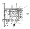
- the contacting station 12 arranged above the article rail 9 in FIG. 4 is shown in greater detail in FIGS. 5, 6 and 7.
- the contacting station 12 To insert a line to be contacted into a housing chamber of a housing 7, the contacting station 12 has a cable insertion opening 28 through which the line end to be fitted is inserted by hand. Perpendicular to the cable insertion opening 28, a contact stamp 29 is arranged above the housing chamber to be fitted, which is held in a receptacle 31 which is adjustable via elongated holes 30. As can further be seen from FIG. 5, the up and down movement of the contacting stamp 29 takes place via an eccentric drive 32. As can be seen from FIGS. 6 and 7, the cable insertion opening 28 is arranged in an exchangeable socket 28a in order to change the machine depending on the line diameter by inserting a new socket 28a with a corresponding cable entry opening 28.
- an article centering device 33 is provided which, as can be seen from FIG. 7, has a rack-like design Holding element 34 has, which is in engagement with teeth formed on the side of the housing 7 facing away from the cable insertion opening 28, so as to position the housing 7 to be fitted in an exact position.
- the loading station 2 has a laser control device 35 in order to determine whether there are gaps between the housings 7 which are conveyed one behind the other along the article rail.
- a dynamic nozzle 36 is arranged opposite the cable insertion opening 28 on the other side of the housing 7 to be fitted sealing against a hole in the back of the housing chamber to be fitted.
- the hole in the rear of the housing chamber is sealed by the line end inserted into the housing chamber through the cable insertion opening 28, so that a dynamic pressure is generated in the dynamic nozzle 36.
- This dynamic pressure is converted via a (not shown) pneumatic-electrical converter into a start signal for actuating the eccentric drive 32 for lowering the contact stamp 29.
- the housing 7 After contacting the line end with the housing 7, the housing 7 is conveyed on via the grid transport device 26 such that the next housing chamber to be fitted comes to lie in front of the cable insertion opening 28 and under the contact stamp 29. After complete assembly, the housing 7 is moved to the test station 13 by means of the grid transport device 26. In order to prevent the test station 13 from being driven over, the article rail 9 has an article brake 37 in the area of the test station 13.
- the test station 13 shown in FIG. 8 consists of at least one vertically movable test pin and at least two horizontally movable test pins 39 arranged parallel to one another. By inserting the test pins 38 and 39, the contact made in the contacting station 12 can be checked for continuity, short circuit and cable Insertion depth can be checked.
- a busbar 40 can be provided behind the test station 13 in the transport direction following the article rail 9 in order to collect the fully assembled housings 7 for further processing or removal.
- the cable assembly device described above works as follows:
- the housings 7 to be fitted slide into the turning device 8 when the article rail 9 of the turning device 8 is in the vertical filling position.
- the housings 7 stacked one behind the other perpendicular to the contact position in the block magazine 5 are then turned 90 ° into the horizontal contact position via the turning device 8 panned.
- the housings 7 located in the turning device 8 are pressed out of the turning device 8 into the buffer zone 11 behind the turning device 8.
- the buffer section 11 enables the machine to work without dead time, since the housings 7 arranged in the buffer section 11 bridge the time required to convey new housings 7 in the direction of the loading station 2 from the block magazine 5 via the turning device 8.
- the housings 7 then reach the assembly station 2 that follows the article feed 1.
- the housings 7 are transported via the grid transport device 26 in such a way that the housing chamber of the housing 7 to be assembled in front of the cable insertion opening 28 comes to rest.
- the cable end to be fitted is then inserted manually into the housing chamber of the housing 7 through the cable insertion opening 28.
- the line end inserted into the housing chamber generates a dynamic pressure on the dynamic nozzle 36 arranged on the opposite side of the cable insertion opening 28, which pressure actuates the eccentric drive 32 of the contacting stamp 29 via a pneumatic-electrical converter.
- the insulation displacement contact element arranged in the housing chamber is pressed onto the line end to be contacted by the lowering contacting stamp 29.
- the housing 7 is conveyed on by the grid transport device 26 by a set grid dimension until the housing 7 is completely equipped.
- the test station 13 In the transport direction behind the contact station 12, the test station 13 is arranged, in which the contact made in the contact station 12 is checked for continuity, short circuit and cable insertion depth via vertical and horizontal test pins 38 and 39. Error messages are immediately displayed to the operating personnel on the plain text display 15 of the control panel 3, so that these incorrectly manufactured articles can be removed manually from the cable assembly device. Line sets that have been contacted correctly can, if necessary, be pushed onto the busbar 40 at the end of the article rail 9 for further processing or removal.
Landscapes
- Engineering & Computer Science (AREA)
- Manufacturing & Machinery (AREA)
- Manufacturing Of Electrical Connectors (AREA)
Priority Applications (2)
| Application Number | Priority Date | Filing Date | Title |
|---|---|---|---|
| EP19950117298 EP0773610B1 (fr) | 1995-11-03 | 1995-11-03 | Procédé et dispositif pour la fabrication semi-automatique de faisceaux de câbles |
| DE59508142T DE59508142D1 (de) | 1995-11-03 | 1995-11-03 | Verfahren und Vorrichtung zur halbautomatischen Herstellung von Leitungssätzen |
Applications Claiming Priority (1)
| Application Number | Priority Date | Filing Date | Title |
|---|---|---|---|
| EP19950117298 EP0773610B1 (fr) | 1995-11-03 | 1995-11-03 | Procédé et dispositif pour la fabrication semi-automatique de faisceaux de câbles |
Publications (2)
| Publication Number | Publication Date |
|---|---|
| EP0773610A1 true EP0773610A1 (fr) | 1997-05-14 |
| EP0773610B1 EP0773610B1 (fr) | 2000-04-05 |
Family
ID=8219772
Family Applications (1)
| Application Number | Title | Priority Date | Filing Date |
|---|---|---|---|
| EP19950117298 Expired - Lifetime EP0773610B1 (fr) | 1995-11-03 | 1995-11-03 | Procédé et dispositif pour la fabrication semi-automatique de faisceaux de câbles |
Country Status (2)
| Country | Link |
|---|---|
| EP (1) | EP0773610B1 (fr) |
| DE (1) | DE59508142D1 (fr) |
Cited By (3)
| Publication number | Priority date | Publication date | Assignee | Title |
|---|---|---|---|---|
| US6035517A (en) * | 1997-12-22 | 2000-03-14 | Qualtron R & D Teoranta | Cable harness production system |
| EP1100164A1 (fr) * | 1999-11-09 | 2001-05-16 | Stocko Contact GmbH & Co. KG | Alimentation de boítiers avec connecteurs électriques |
| CN112186453A (zh) * | 2019-07-04 | 2021-01-05 | 矢崎(中国)投资有限公司 | 端子焊接设备 |
Citations (3)
| Publication number | Priority date | Publication date | Assignee | Title |
|---|---|---|---|---|
| EP0154748A2 (fr) * | 1984-02-27 | 1985-09-18 | Molex Incorporated | Système d'alimentation pour connecteurs |
| EP0332363A1 (fr) * | 1988-03-08 | 1989-09-13 | The Whitaker Corporation | Procédé de fonctionnement d'une machine de câblage |
| US4918804A (en) * | 1989-03-06 | 1990-04-24 | Molex Incorporated | Modular application tooling for electrical connectors |
-
1995
- 1995-11-03 EP EP19950117298 patent/EP0773610B1/fr not_active Expired - Lifetime
- 1995-11-03 DE DE59508142T patent/DE59508142D1/de not_active Expired - Fee Related
Patent Citations (3)
| Publication number | Priority date | Publication date | Assignee | Title |
|---|---|---|---|---|
| EP0154748A2 (fr) * | 1984-02-27 | 1985-09-18 | Molex Incorporated | Système d'alimentation pour connecteurs |
| EP0332363A1 (fr) * | 1988-03-08 | 1989-09-13 | The Whitaker Corporation | Procédé de fonctionnement d'une machine de câblage |
| US4918804A (en) * | 1989-03-06 | 1990-04-24 | Molex Incorporated | Modular application tooling for electrical connectors |
Cited By (3)
| Publication number | Priority date | Publication date | Assignee | Title |
|---|---|---|---|---|
| US6035517A (en) * | 1997-12-22 | 2000-03-14 | Qualtron R & D Teoranta | Cable harness production system |
| EP1100164A1 (fr) * | 1999-11-09 | 2001-05-16 | Stocko Contact GmbH & Co. KG | Alimentation de boítiers avec connecteurs électriques |
| CN112186453A (zh) * | 2019-07-04 | 2021-01-05 | 矢崎(中国)投资有限公司 | 端子焊接设备 |
Also Published As
| Publication number | Publication date |
|---|---|
| DE59508142D1 (de) | 2000-05-11 |
| EP0773610B1 (fr) | 2000-04-05 |
Similar Documents
| Publication | Publication Date | Title |
|---|---|---|
| DE2649920C2 (de) | Kontaktieranlage für isolierte elektrische Leitungsdrähte | |
| DE2619657C2 (fr) | ||
| DE19512144B4 (de) | Automatische Transportvorrichtung mit einem Anschlagmechanismus zum Positionieren von Prüftabletts | |
| DE19603281C2 (de) | Vorrichtung zur Herstellung von unter Preßsitz zusammengefügten elektrischen Kabelbäumen und zugehöriges Verfahren | |
| DE69521865T2 (de) | Vorrichtung zum Anschliessen von elektrischen Kabelbäumen | |
| DE3685814T2 (de) | Zusammenbau eines elektrischen verbinders und verfahren zur ausfuehrung desselben. | |
| DE3005652B1 (de) | Mehrpolige elektrische Steckverbinder-Vorrichtung | |
| DE3908867C2 (fr) | ||
| EP0514671B1 (fr) | Dispositif de test | |
| EP0773610B1 (fr) | Procédé et dispositif pour la fabrication semi-automatique de faisceaux de câbles | |
| DE19532130C2 (de) | Vorrichtung und Verfahren zum Herstellen eines Kabelbaums | |
| DE3879815T2 (de) | Bündelempfangsapparat. | |
| CH673370A5 (fr) | ||
| DE2801115A1 (de) | Gehaeusebestueckungsverfahren sowie vorrichtung zu seiner durchfuehrung | |
| DE3434883A1 (de) | Einsetzvorrichtung fuer elektronische bauteile | |
| DE69711796T2 (de) | Verfahren zur Herstellung eines Kabelbaumes | |
| DE69213035T2 (de) | Modulares Presswerkzeug für den Zusammenbau und das Anschliessen von elektrischen Steckverbindern | |
| EP0474113B1 (fr) | Dispositif de connexion pour câbles multifilaires | |
| EP0601448B1 (fr) | Procédé et dispositif de fabrication automatique de jeux de câbles | |
| DE3414321C2 (fr) | ||
| WO2010105729A1 (fr) | Dispositif pour amener un conducteur en butée contre un élément de raccordement | |
| EP0773612B1 (fr) | Dispositif pour la fabrication semi-automatique de faisceaux de câbles | |
| DE4342386C1 (de) | Verfahren und Vorrichtung zum Konfektionieren von TAE-Steckern | |
| DE19708032C2 (de) | Verbinder-Zuführverfahren und Verbinder-Zuführvorrichtung | |
| DE4302120C2 (de) | Vorrichtung zum Speichern und zum Bereitstellen von zahlreichen Koaxialleitungen für die Steckermontage |
Legal Events
| Date | Code | Title | Description |
|---|---|---|---|
| PUAI | Public reference made under article 153(3) epc to a published international application that has entered the european phase |
Free format text: ORIGINAL CODE: 0009012 |
|
| 17P | Request for examination filed |
Effective date: 19960918 |
|
| AK | Designated contracting states |
Kind code of ref document: A1 Designated state(s): BE DE FR GB IT SE |
|
| 17Q | First examination report despatched |
Effective date: 19980326 |
|
| GRAG | Despatch of communication of intention to grant |
Free format text: ORIGINAL CODE: EPIDOS AGRA |
|
| GRAG | Despatch of communication of intention to grant |
Free format text: ORIGINAL CODE: EPIDOS AGRA |
|
| GRAH | Despatch of communication of intention to grant a patent |
Free format text: ORIGINAL CODE: EPIDOS IGRA |
|
| GRAH | Despatch of communication of intention to grant a patent |
Free format text: ORIGINAL CODE: EPIDOS IGRA |
|
| GRAA | (expected) grant |
Free format text: ORIGINAL CODE: 0009210 |
|
| AK | Designated contracting states |
Kind code of ref document: B1 Designated state(s): BE DE FR GB IT SE |
|
| GBT | Gb: translation of ep patent filed (gb section 77(6)(a)/1977) |
Effective date: 20000419 |
|
| REF | Corresponds to: |
Ref document number: 59508142 Country of ref document: DE Date of ref document: 20000511 |
|
| ITF | It: translation for a ep patent filed | ||
| ET | Fr: translation filed | ||
| PLBE | No opposition filed within time limit |
Free format text: ORIGINAL CODE: 0009261 |
|
| STAA | Information on the status of an ep patent application or granted ep patent |
Free format text: STATUS: NO OPPOSITION FILED WITHIN TIME LIMIT |
|
| 26N | No opposition filed | ||
| REG | Reference to a national code |
Ref country code: GB Ref legal event code: IF02 |
|
| PGFP | Annual fee paid to national office [announced via postgrant information from national office to epo] |
Ref country code: SE Payment date: 20021028 Year of fee payment: 8 |
|
| PGFP | Annual fee paid to national office [announced via postgrant information from national office to epo] |
Ref country code: GB Payment date: 20021030 Year of fee payment: 8 |
|
| PGFP | Annual fee paid to national office [announced via postgrant information from national office to epo] |
Ref country code: FR Payment date: 20021104 Year of fee payment: 8 |
|
| PGFP | Annual fee paid to national office [announced via postgrant information from national office to epo] |
Ref country code: BE Payment date: 20021106 Year of fee payment: 8 |
|
| PGFP | Annual fee paid to national office [announced via postgrant information from national office to epo] |
Ref country code: DE Payment date: 20030127 Year of fee payment: 8 |
|
| PG25 | Lapsed in a contracting state [announced via postgrant information from national office to epo] |
Ref country code: GB Free format text: LAPSE BECAUSE OF NON-PAYMENT OF DUE FEES Effective date: 20031103 |
|
| PG25 | Lapsed in a contracting state [announced via postgrant information from national office to epo] |
Ref country code: SE Free format text: LAPSE BECAUSE OF NON-PAYMENT OF DUE FEES Effective date: 20031104 |
|
| PG25 | Lapsed in a contracting state [announced via postgrant information from national office to epo] |
Ref country code: BE Free format text: LAPSE BECAUSE OF NON-PAYMENT OF DUE FEES Effective date: 20031130 |
|
| BERE | Be: lapsed |
Owner name: *STOCKO METALLWARENFABRIKEN HENKELS UND SOHN G.M.B Effective date: 20031130 |
|
| PG25 | Lapsed in a contracting state [announced via postgrant information from national office to epo] |
Ref country code: DE Free format text: LAPSE BECAUSE OF NON-PAYMENT OF DUE FEES Effective date: 20040602 |
|
| GBPC | Gb: european patent ceased through non-payment of renewal fee |
Effective date: 20031103 |
|
| EUG | Se: european patent has lapsed | ||
| PG25 | Lapsed in a contracting state [announced via postgrant information from national office to epo] |
Ref country code: FR Free format text: LAPSE BECAUSE OF NON-PAYMENT OF DUE FEES Effective date: 20040730 |
|
| REG | Reference to a national code |
Ref country code: FR Ref legal event code: ST |
|
| PG25 | Lapsed in a contracting state [announced via postgrant information from national office to epo] |
Ref country code: IT Free format text: LAPSE BECAUSE OF NON-PAYMENT OF DUE FEES;WARNING: LAPSES OF ITALIAN PATENTS WITH EFFECTIVE DATE BEFORE 2007 MAY HAVE OCCURRED AT ANY TIME BEFORE 2007. THE CORRECT EFFECTIVE DATE MAY BE DIFFERENT FROM THE ONE RECORDED. Effective date: 20051103 |