EP1100164A1 - Alimentation de boítiers avec connecteurs électriques - Google Patents
Alimentation de boítiers avec connecteurs électriques Download PDFInfo
- Publication number
- EP1100164A1 EP1100164A1 EP99122273A EP99122273A EP1100164A1 EP 1100164 A1 EP1100164 A1 EP 1100164A1 EP 99122273 A EP99122273 A EP 99122273A EP 99122273 A EP99122273 A EP 99122273A EP 1100164 A1 EP1100164 A1 EP 1100164A1
- Authority
- EP
- European Patent Office
- Prior art keywords
- housing
- magazines
- loading arm
- loading
- magazine
- Prior art date
- Legal status (The legal status is an assumption and is not a legal conclusion. Google has not performed a legal analysis and makes no representation as to the accuracy of the status listed.)
- Granted
Links
- 230000000712 assembly Effects 0.000 title description 2
- 238000000429 assembly Methods 0.000 title description 2
- 230000005484 gravity Effects 0.000 claims abstract description 5
- 238000003860 storage Methods 0.000 claims description 21
- 238000006073 displacement reaction Methods 0.000 claims description 8
- 238000009413 insulation Methods 0.000 claims description 6
- 238000004519 manufacturing process Methods 0.000 claims description 4
- 239000000969 carrier Substances 0.000 description 6
- 239000004020 conductor Substances 0.000 description 3
- 230000033001 locomotion Effects 0.000 description 2
- 238000000034 method Methods 0.000 description 2
- 230000005540 biological transmission Effects 0.000 description 1
- 238000006243 chemical reaction Methods 0.000 description 1
- 238000005352 clarification Methods 0.000 description 1
- 238000005520 cutting process Methods 0.000 description 1
- 230000006870 function Effects 0.000 description 1
- 230000002441 reversible effect Effects 0.000 description 1
- 238000011144 upstream manufacturing Methods 0.000 description 1
Images


Classifications
-
- H—ELECTRICITY
- H01—ELECTRIC ELEMENTS
- H01R—ELECTRICALLY-CONDUCTIVE CONNECTIONS; STRUCTURAL ASSOCIATIONS OF A PLURALITY OF MUTUALLY-INSULATED ELECTRICAL CONNECTING ELEMENTS; COUPLING DEVICES; CURRENT COLLECTORS
- H01R43/00—Apparatus or processes specially adapted for manufacturing, assembling, maintaining, or repairing of line connectors or current collectors or for joining electric conductors
- H01R43/01—Apparatus or processes specially adapted for manufacturing, assembling, maintaining, or repairing of line connectors or current collectors or for joining electric conductors for connecting unstripped conductors to contact members having insulation cutting edges
-
- B—PERFORMING OPERATIONS; TRANSPORTING
- B23—MACHINE TOOLS; METAL-WORKING NOT OTHERWISE PROVIDED FOR
- B23P—METAL-WORKING NOT OTHERWISE PROVIDED FOR; COMBINED OPERATIONS; UNIVERSAL MACHINE TOOLS
- B23P19/00—Machines for simply fitting together or separating metal parts or objects, or metal and non-metal parts, whether or not involving some deformation; Tools or devices therefor so far as not provided for in other classes
- B23P19/001—Article feeders for assembling machines
Definitions
- the invention relates to a device for feeding with plugs, especially insulation displacement contact elements, equipped housings to a Cable assembly machine for the automatic production of cable sets, with a vertical storage device for holding rod-shaped Magazines in which the housings are arranged one behind the other, and with a Position handling system for the transport of the housing to a housing workpiece carrier, the - equipped with housings - a processing station Cable assembly machine can be fed for contacting.
- Such an article feed is known from the applicant's EP 0 756 358 B1 known.
- the housings are horizontally in contact position one behind the other Housing receiving rods arranged to one another to be tracked Block magazines stacked and in associated feed channels using a Ejection device can be emptied.
- the horizontal arrangement of the Housing support rods require an active one for emptying Extension device that must be controlled precisely and its own reversible drive must have. This is disadvantageously high apparatus expenditure.
- This applies equally to the necessary The presence of a plurality of feed channels arranged parallel to one another below the vertical storage devices and a transverse traversing device that can be moved in front of them, which makes it possible to make housings the same from the feed channels and / or different number of poles by means of the extension unit in the contact position to record.
- the invention is based on the object of improving the supply of articles to a cable assembly machine while avoiding the disadvantages mentioned above and, in particular, of achieving a high degree of flexibility with regard to the arrangement of housings of the same and / or different number of poles in a simple manner It is possible that reloading with magazines without a machine stop can be carried out in order to avoid downtimes and that there are no conversion times when loading other articles, so that just-in-time production can be realized.
- the object is inventively achieved in that the magazines are arranged in the vertical storage device vertically such that the removal of the therein vertically above each other located casing takes place automatically by gravity, in that in transport direction of the housing subsequent to the vertical memory means a approachable with the location handling system transfer station with a 90 ° turning device is arranged in which the housing can be brought from its vertical position into the horizontal contact position and can be inserted into the housing workpiece carrier.
- the magazines are preferably composed of a plurality, in particular three housing mounting rods glued together to form a block magazine formed in a radial orientation perpendicular to an arc Magazine holder are held, the magazine holder a variety of Block magazines radially aligned in vertical positioning, next to each other arranged, carries.
- the housing mounting rods are open Plastic tubes of rectangular cross section, the profile of which essentially corresponds to that The outer contour of the housing is adapted.
- the magazines in holding compartments arranged radially on the magazine holder which are open at the bottom for removal and expediently with a pin-like projection and a stop for setting the magazine position are provided against displacement in the radial direction.
- a removable fuse for removal arranged to prevent the housing from falling out, preferably in the form of a radial extending locking bolt.
- This can be seen from the removal opening closing closed position in the radial direction to the outside for removal the housing is pulled away or pushed away, preferably on the Underside of the locking bolt a rope pulley is arranged over which a wire rope is performed, for the purpose of retracting the locking bolt in the closed position is connected to a pneumatic cylinder.
- the arc is Magazine holder designed as an annular semi-circular table and is a additional upper corresponding magazine holder provided.
- Position handling system is preferably a loading arm used in a horizontal position around the central axis of the magazine holder the individual magazines in the Approach the removal level, remove the individual housings and go to the Transfer station can move. Instead of using a loading arm this It would also be conceivable to use the magazine holder as a rotary table in the manner of a Form revolver magazine and the transport process by moving the turntable itself to the unloading station.
- the loading arm is expediently provided with a movable in the radial direction
- telescopic slider the outer end of which carries a loading carriage that has one or two vertically extending housing receiving tracks and under the removal opening of one or more magazines to be controlled can be moved by a servomotor.
- the radial extension or retraction via a toothed belt drive on the loading arm with roller guide of the Telescopic slide can be carried out in a simple manner, the Telescopic slide with advantage on the side of the loading arm and the toothed belt drive the top of the loading arm is arranged.
- the loading carriage arranged at the outer end of the loading arm points in the Track recording track a height adjustable stop, which for Positioning the housing in the housing receiving track serves and for The housing is removed from the recording track into the 90 ° turning device is removable outside. Since in the preferred embodiment article feed according to the invention two housing recording tracks in parallel are provided to each other on the loading carriage, the stop is this Embodiment fork-shaped, one of the for height adjustment Loading arm approachable setting station is provided, which preferably consists of a Servomotor and a spindle or rack and pinion gear, which one vertically movable adjustment rod actuated, via which the positioning of the adjustable stop on the loading carriage.
- the transfer station preferably has two parallel to one another perpendicular arranged handover marks on the bottom by an opening lock are closed, under which the 90 ° turning device with a Recording track for housing for loading the housing workpiece carrier in Contacting position is by means of a push-out device.
- the transfer station is preferably designed so that it can be pushed back and forth, to be able to position the transfer tracks coaxially to the recording track.
- the article feed described above is essentially semicircular trained and suitable for the one-sided assembly of cables in the Plugs located in the housing, in particular insulation displacement contact elements, to make. Although such a one-sided assembly is required, it is the production of cable harnesses or cable branches as a rule, the Lines at both ends with insulation displacement contact elements for the opposite processing of any assembly variants contacted are. To make this possible, an article feed must be closed on the contacting machine Both ends of the line to the left and right of the plane of symmetry are required. With The advantage of the article feeder according to the invention is accordingly proposed the vertical storage devices, position handling systems and transfer stations for the housing workpiece carriers symmetrical on both sides to the longitudinal axis of the processing station of the cable assembly machine to arrange.
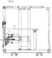
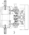
- the cable assembly machine shown in Fig. 1 of the drawing shows schematically several consecutive assembly modules 1, 2, 3, 4, which each have a processing station 5 with a turning tongs 6, which 7 individual conductors are fed from the back of a line supply, which in the processing station 5 on both sides after cutting to length with so-called articles, that is, housings equipped with insulation displacement contact elements, be contacted.
- the supply of the housing to the processing station 5 takes place with the article feed 8 shown on the right in FIG. 1 of the drawing both sides of the processing station 5 for the purpose of providing IDC contact elements for opposing processing of any assembly variants supplied on both ends of the conductor.
- the Article feed 8 is shown in more detail in FIGS. 2 to 10 of the drawing.
- the article feed 8 has a machine frame 9 , which has a vertical storage device 10 for magazines at working height 11 bears in which housings equipped with insulation displacement contact elements are stored.
- a similar vertical storage device 10 ' is found on the opposite half-side of the frame 9, from which the second side of the Processing station 5 is operated.
- Each of the rod-shaped magazines 11 consists of three housing mounting rods 12 glued together (see Fig. 4), which have a length of approximately 800 mm and in profile essentially to the Outer contour of the housing are adapted.
- the magazines 11 are in the Vertical storage device 10 arranged vertically so that the Removal of the vertical in the individual housing support rods 12 superimposed housings can take place automatically by gravity, if the normally closed discharge opening below is opened.
- the articles are removed from the magazines by means of a Position handling system 13 or 14, described in more detail below, with which the the magazine 11 in the desired clothing variant (according to cable harness to be produced) removed and assembled housing a transfer station 15 or 16 are supplied, in which the housing from their vertical position in the horizontal contact position and in one Housing workpiece carriers 17 and 18 can be inserted.
- the in the Housing workpiece carriers 17 and 18 compiled in this way and housing modules for contacting the conductors on both sides with a transport device of the processing station not described in detail 5 fed and contacted there.
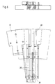
- Fig. 3 of the drawing shows the article feed 8 in sections from a 90 ° 2 side view offset to the viewing position of FIG Positioning of the transfer station 15 with associated 90 ° turning device 19 to clarify.
- FIGS. 4 to 10 shown in FIGS Article feed 8 refer only to one side of the for simplification Article feeder, which is used for the delivery of the articles to contact a Head end is provided.
- the article feed to the other side is in principle constructed in the same way so that in order to avoid repetitions on the re-description of this part of the article feeder can be omitted.
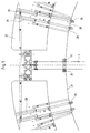
- the vertical storage device 10 has a lower one according to FIG. 2 of the drawing arcuate magazine holder 20 and parallel to it an upper distance Corresponding magazine holder 21, between which a variety of Block magazines 11 described above in vertical positioning radially are aligned next to each other.
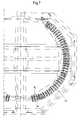
- Fig. 4 of the drawing shows in a Top view of the lower magazine holder 20, which consists of an annular, almost semicircular table 22 with receiving compartments 23 formed thereon Holder of the magazine 11 is made.
- Each storage compartment 23 extends in radial direction to the vertical central axis 24 and is limited by two with Distance from each other, about 2 cm high webs 25, 26 between the side by side two magazines 11, each consisting of three Housing receiving rods 12 can be inserted up to a stop 27, the is designed to prevent the magazine position from shifting in the radial direction Direction.
- the Storage compartments 23 open at the bottom to allow removal of the housing enable, as described in more detail below.
- the wire rope 31 is with his one end attached to a fixed point of the vertical storage device, then guided in a semicircle over all the pulleys 30 of the locking bolt 28 and with connected at its other end to the pneumatic cylinder 32.
- Cable guides can be arranged on the machine frame 9 additional deflection rollers 33 his.
- the upper magazine holder 20 shown in FIG. 7 acts with the lower magazine holder 20 Magazine holder 21 together, the corresponding receiving compartments 34 for has the upper ends of the magazines 11, each with a side Leaf spring 35 are equipped to improve the clamp bracket.
- Magazine-packed housings must be removed individually, for modules any assembly variants are put together and then the Housing workpiece carrier 17 or 18 are passed, with which then via a separate transport system the feed to the processing station 1 of the Cable assembly machine is done.
- a special position handling system 13 or 14 provided, which as essential element has a loading arm 36 which is horizontal Positioning about the central axis 24 slightly below the lower one Magazine holder 20 is rotatably mounted and servo-controlled the individual Magazine 11 can approach in the removal level, the individual housing remove and move to the transfer station 16 according to FIG. 4 of the drawing can.
- Two positions of the loading arm 36 are in Fig. 4 of the drawing Clarification of the function shown, while constructive details of the Fig.
- the loading arm 36 consists of a hollow section beam with a rectangular cross section, the inner end of which can be rotated is mounted on the vertical central axis 24 and there via a drive connected servo motor 37 over a semicircular range of motion can be moved such that each receiving compartment 23 and consequently each Magazine 11 can be approached precisely.
- the one at its outside free end Carriage 40 carries the two arranged side by side vertically Tracks 41, 42 for receiving housings from two side by side arranged housing receiving rods 12 of two magazines 11 is provided.
- the tracks 41, 42 cannot be seen in the side view of FIG. 8 and are therefore indicated by a reference arrow. They have a cross section according to the outer shape of the housing and can each in a plurality of housings arranged vertically one above the other record that are removed from the housing support rods 12.
- a toothed belt drive 43 is positioned, which has a separate servo drive 44 is movable in both directions of rotation.
- One arranged on the toothed belt Carrier 45 detects the telescopic slide 39, which moves out accordingly is retractable.
- a roller guide and storage with rollers 46 for one slight mobility has been applied.
- the loading carriage 40 arranged at the outer end of the loading arm 36 points in each housing receiving track 41, 42 has a height-adjustable stop 47 on that for positioning the housing in the respective housing receiving track 41, 42 and serves to remove the housing from the respective Housing receiving track 41, 42 and transfer to the 90 ° turning device 19 can be moved outwards.
- the stop 47 is in the specific embodiment fork-shaped, with its two fork arms into the To be able to intervene in housing receiving tracks 41, 42.
- Setting station 48 which consists of a servo motor 49 and a Ball screw transmission 50, which has a vertically movable adjusting rod 51 actuated, via which the positioning of the height-adjustable stop 47 on Loading carriage 40 is made.
- the transfer station 15 or 16 is on the Side of processing station 5 at the end of the 180 ° travel of the loading arm 36 arranged and positioned below the loading carriage 40 that the housings located therein from their housing receiving tracks 41, 42 in two Coaxially arranged, perpendicular transfer tracks 52, 53 fall can when the stop 47 has moved away from the locked position and the Tracks are released.
- the transfer tracks 52, 53 are also each below by one to be opened Closing lock 54 closed, which are actuated by a servo motor 55.
- Closing lock 54 closed which are actuated by a servo motor 55.
- 9 of the drawing is due to the manner of representation only a locking lock 54 recognizable in the left area of the article feed.
- Opening the Locking device 54 fall in the respective transfer track 52 or 53 Housing assemblies in the 90 ° turning device arranged below the track 19, which is shown in Fig. 10 of the drawing.
- To be able to move the transfer station laterally by means of the Cylinder 56 is provided in the direction of the arrow according to FIG. 9 of the drawing.
- the 90 ° turning device 19 has a recording track 57 for in FIG. 10 drawn in housing 58, which initially in a vertical position the transfer station can be picked up and then by means of a Rotary cylinder 59 in the horizontal position shown in Fig. 10 of the drawing the recording track 57 are pivoted. In a manner not shown then the housing by means of a push-out device in the front arranged housing workpiece carriers 17 and 18 as the assembly variant correspondingly assembled housing module inserted and the Contacting supplied.
- the article feeder works as follows:
- the two are essentially arranged in a circle Load vertical storage devices 10 and 10 'with filled magazines 11.
- two block magazines each, that is, three with each other glued housing support rods 12 assembled magazines, inserted side by side into each receiving compartment 23 from the outside and secured against radial displacement by means of the stop 27.
- the removal opening at the bottom of the magazines is then one at a time Locking bolt 28 closed per block magazine, so that the housing does not follow can fall out below.
- the vertical storage devices 10 can now each have a loading arm 36 or 10 'for removing housings from the magazines.
- the loading arm 36 is first of all by means of its servo drive 37 middle position on the corresponding semicircle to the one located there Move setting station 38.
- the stop is then via their servo drive 47 on the loading carriage 40 corresponding to that provided for contacting Housing correctly adjusted according to the specified number of poles.
- the telescopic slide 39 is Servo motor 44 and toothed belt drive 43 advanced to the outside, detected in the process with a leading edge, the two locking bolts 28 of the approached Receiving compartments 23 so that the removal openings are released and the Housing 58 in the housing receiving tracks 41 solely due to its gravity and 42 of the loading carriage 40 fall.
- the telescopic slide 39 is then on the Servo drive 44 retracted, with the two locking bolts 28 can be pulled back into their closed position by using the wire rope 31 and the two pulleys 30 on the locking bolts by means of the connected Pneumatic cylinder 32 a corresponding retraction force is exerted.
- the housings fall into the two coaxially arranged Transfer tracks 52 and 53 of the transfer station and are in these tracks each held a lock located below.
- the loading carriage 40 is now closed a new loading free, for which purpose the loading arm 36 for reloading either moves directly to a corresponding receiving compartment 23 or in Depending on the program, first to the setting station 48.
- the transfer lane 52 or 53 is opened by pulling the lock away, which is located coaxially over the recording track 57 of the 90 ° turning device.
- the housing falls into the receiving track 57, which is then through the turning device is rotated by 90 ° so that it is arranged coaxially horizontally to the one in front Housing workpiece carrier 17 or 18 is.
- Its loading then takes place by means of a push-out device instead of the assembled housing module detected from behind in the receiving track 57 and in the upstream housing workpiece carrier shifts.
- the emptied 90 ° turning device 19 is then turned back to the vertical position. In the meantime is by side Moving the second handover lane has been moved to a position that again is coaxial to the recording track 57 of the 90 ° turning device, so that after the lock has been removed, refill the turning device
- the second transfer lane can be emptied.
- the filled housing workpiece carriers are supplied with a separate one Transport device of the processing station 5 supplied.
Landscapes
- Engineering & Computer Science (AREA)
- Manufacturing & Machinery (AREA)
- Mechanical Engineering (AREA)
- Specific Conveyance Elements (AREA)
- Jellies, Jams, And Syrups (AREA)
- Polysaccharides And Polysaccharide Derivatives (AREA)
- General Preparation And Processing Of Foods (AREA)
- Manufacturing Of Electrical Connectors (AREA)
- Automatic Assembly (AREA)
Priority Applications (5)
| Application Number | Priority Date | Filing Date | Title |
|---|---|---|---|
| ES99122273T ES2175891T3 (es) | 1999-11-09 | 1999-11-09 | Alimentacion de articulos. |
| DE59901142T DE59901142D1 (de) | 1999-11-09 | 1999-11-09 | Artikelzuführung |
| AT99122273T ATE339874T1 (de) | 1999-11-09 | 1999-11-09 | Artikelzuführung |
| EP99122273A EP1100164B1 (fr) | 1999-11-09 | 1999-11-09 | Alimentation de boítiers avec connecteurs électriques |
| TR2000/03283A TR200003283A2 (tr) | 1999-11-09 | 2000-11-08 | Parça sürme tertibatı. |
Applications Claiming Priority (1)
| Application Number | Priority Date | Filing Date | Title |
|---|---|---|---|
| EP99122273A EP1100164B1 (fr) | 1999-11-09 | 1999-11-09 | Alimentation de boítiers avec connecteurs électriques |
Publications (2)
| Publication Number | Publication Date |
|---|---|
| EP1100164A1 true EP1100164A1 (fr) | 2001-05-16 |
| EP1100164B1 EP1100164B1 (fr) | 2002-04-03 |
Family
ID=8239351
Family Applications (1)
| Application Number | Title | Priority Date | Filing Date |
|---|---|---|---|
| EP99122273A Expired - Lifetime EP1100164B1 (fr) | 1999-11-09 | 1999-11-09 | Alimentation de boítiers avec connecteurs électriques |
Country Status (5)
| Country | Link |
|---|---|
| EP (1) | EP1100164B1 (fr) |
| AT (1) | ATE339874T1 (fr) |
| DE (1) | DE59901142D1 (fr) |
| ES (1) | ES2175891T3 (fr) |
| TR (1) | TR200003283A2 (fr) |
Cited By (3)
| Publication number | Priority date | Publication date | Assignee | Title |
|---|---|---|---|---|
| CN106041442A (zh) * | 2016-07-20 | 2016-10-26 | 梁启明 | 一种静脉针外壳的上料装置 |
| EP3249762A1 (fr) * | 2016-05-23 | 2017-11-29 | Komax Holding AG | Dispositif pour une machine de traitement de cable destine au chargement automatique et de preference au dechargement de logements de boitier de connexion comprenant des boitiers de connexion correspondants |
| CN109742634A (zh) * | 2019-02-20 | 2019-05-10 | 东莞市亿善自动化设备科技有限公司 | 一种线材定位插壳机构 |
Citations (5)
| Publication number | Priority date | Publication date | Assignee | Title |
|---|---|---|---|---|
| US4055889A (en) * | 1976-02-18 | 1977-11-01 | Molex Incorporated | Connector harness assembly machine |
| US4344225A (en) * | 1980-02-25 | 1982-08-17 | Amp Incorporated | Pre-assembly and terminating apparatus |
| US4489488A (en) * | 1982-04-13 | 1984-12-25 | At&T Technologies, Inc. | Methods of and apparatus for assembling an article into a housing |
| US5210942A (en) * | 1988-06-18 | 1993-05-18 | Merz Metall-Und Kunststoffverarbeitungs Gmbh | Method for producing cable harnesses |
| EP0773610A1 (fr) * | 1995-11-03 | 1997-05-14 | STOCKO Metallwarenfabriken Henkels und Sohn GmbH & Co | Procédé et dispositif pour la fabrication semi-automatique de faisceaux de câbles |
-
1999
- 1999-11-09 ES ES99122273T patent/ES2175891T3/es not_active Expired - Lifetime
- 1999-11-09 EP EP99122273A patent/EP1100164B1/fr not_active Expired - Lifetime
- 1999-11-09 DE DE59901142T patent/DE59901142D1/de not_active Expired - Fee Related
- 1999-11-09 AT AT99122273T patent/ATE339874T1/de not_active IP Right Cessation
-
2000
- 2000-11-08 TR TR2000/03283A patent/TR200003283A2/xx unknown
Patent Citations (5)
| Publication number | Priority date | Publication date | Assignee | Title |
|---|---|---|---|---|
| US4055889A (en) * | 1976-02-18 | 1977-11-01 | Molex Incorporated | Connector harness assembly machine |
| US4344225A (en) * | 1980-02-25 | 1982-08-17 | Amp Incorporated | Pre-assembly and terminating apparatus |
| US4489488A (en) * | 1982-04-13 | 1984-12-25 | At&T Technologies, Inc. | Methods of and apparatus for assembling an article into a housing |
| US5210942A (en) * | 1988-06-18 | 1993-05-18 | Merz Metall-Und Kunststoffverarbeitungs Gmbh | Method for producing cable harnesses |
| EP0773610A1 (fr) * | 1995-11-03 | 1997-05-14 | STOCKO Metallwarenfabriken Henkels und Sohn GmbH & Co | Procédé et dispositif pour la fabrication semi-automatique de faisceaux de câbles |
Cited By (4)
| Publication number | Priority date | Publication date | Assignee | Title |
|---|---|---|---|---|
| EP3249762A1 (fr) * | 2016-05-23 | 2017-11-29 | Komax Holding AG | Dispositif pour une machine de traitement de cable destine au chargement automatique et de preference au dechargement de logements de boitier de connexion comprenant des boitiers de connexion correspondants |
| CN106041442A (zh) * | 2016-07-20 | 2016-10-26 | 梁启明 | 一种静脉针外壳的上料装置 |
| CN106041442B (zh) * | 2016-07-20 | 2023-10-27 | 梁启明 | 一种静脉针外壳的上料装置 |
| CN109742634A (zh) * | 2019-02-20 | 2019-05-10 | 东莞市亿善自动化设备科技有限公司 | 一种线材定位插壳机构 |
Also Published As
| Publication number | Publication date |
|---|---|
| ES2175891T3 (es) | 2002-11-16 |
| DE59901142D1 (de) | 2002-05-08 |
| EP1100164B1 (fr) | 2002-04-03 |
| ATE339874T1 (de) | 2002-04-15 |
| TR200003283A2 (tr) | 2001-06-21 |
Similar Documents
| Publication | Publication Date | Title |
|---|---|---|
| EP1982799B1 (fr) | Agencement de manipulation | |
| EP1955789B1 (fr) | Cintreuse | |
| DE1602951C3 (de) | Mehrspindel-Bohrmaschine | |
| DE3502611C2 (fr) | ||
| DE69607816T2 (de) | Stangenvorschubvorrichtung, insbesondere für dünne Stangen in automatischen Zuführvorrichtungen | |
| EP0363368B1 (fr) | Systeme de transport pour installations de montage | |
| EP0671228A2 (fr) | Installation de transport pour pièces à usiner dans une presse | |
| DE3017613C2 (fr) | ||
| EP0212077B1 (fr) | Dispositif de guidage de barres | |
| DE4329179A1 (de) | Maschine zum Umsetzen von Artikeln in eine Verpackungseinheit | |
| EP3331792B1 (fr) | Dispositif de remplissage d'un pot de filature avec un ruban de fibres | |
| EP2939767B1 (fr) | Embarreur avec magasin | |
| EP0256523A1 (fr) | Transporteur | |
| EP1079479A1 (fr) | Dispositif pour déposer des câbles | |
| DE3410656C2 (fr) | ||
| EP1194266B1 (fr) | Dispositif de changement d'outil destine a une machine-outil | |
| EP1100164B1 (fr) | Alimentation de boítiers avec connecteurs électriques | |
| DE3115481C2 (de) | Werkstückpaletten-Speicher für ein Bearbeitungszentrum | |
| DE4124356C1 (en) | Pipe bending machine with clamping head on frame - which forms support column with top cantilever arm whose free end forms bearing for rotary head | |
| DE19852046C1 (de) | Vorrichtung zur Herstellung von Brezeln | |
| EP0503016B1 (fr) | Dispositif pour la manutention automatique de douilles de cannettes et de cannettes bobinees de metiers a tisser | |
| DE9017476U1 (de) | Einrichtung zum Übergeben von Bobinen aus Verpackungsmaterial | |
| EP3880381B1 (fr) | Dispositif de cintrage de pièces en forme de barre | |
| DE3421177C2 (fr) | ||
| DE4212903C2 (fr) |
Legal Events
| Date | Code | Title | Description |
|---|---|---|---|
| PUAI | Public reference made under article 153(3) epc to a published international application that has entered the european phase |
Free format text: ORIGINAL CODE: 0009012 |
|
| GRAG | Despatch of communication of intention to grant |
Free format text: ORIGINAL CODE: EPIDOS AGRA |
|
| 17P | Request for examination filed |
Effective date: 20000403 |
|
| AK | Designated contracting states |
Kind code of ref document: A1 Designated state(s): BE DE ES FR GB IT NL |
|
| AX | Request for extension of the european patent |
Free format text: AL;LT;LV;MK;RO;SI |
|
| 17Q | First examination report despatched |
Effective date: 20010528 |
|
| GRAG | Despatch of communication of intention to grant |
Free format text: ORIGINAL CODE: EPIDOS AGRA |
|
| GRAH | Despatch of communication of intention to grant a patent |
Free format text: ORIGINAL CODE: EPIDOS IGRA |
|
| GRAH | Despatch of communication of intention to grant a patent |
Free format text: ORIGINAL CODE: EPIDOS IGRA |
|
| REG | Reference to a national code |
Ref country code: GB Ref legal event code: IF02 |
|
| AKX | Designation fees paid |
Free format text: BE DE ES FR GB IT NL |
|
| GRAA | (expected) grant |
Free format text: ORIGINAL CODE: 0009210 |
|
| AK | Designated contracting states |
Kind code of ref document: B1 Designated state(s): BE DE ES FR GB IT NL Kind code of ref document: B1 Designated state(s): AT BE CH CY DE DK ES FI FR GB GR IE IT LI LU MC NL PT SE |
|
| PG25 | Lapsed in a contracting state [announced via postgrant information from national office to epo] |
Ref country code: LU Free format text: LAPSE BECAUSE OF FAILURE TO SUBMIT A TRANSLATION OF THE DESCRIPTION OR TO PAY THE FEE WITHIN THE PRESCRIBED TIME-LIMIT Effective date: 20020403 Ref country code: IE Free format text: LAPSE BECAUSE OF FAILURE TO SUBMIT A TRANSLATION OF THE DESCRIPTION OR TO PAY THE FEE WITHIN THE PRESCRIBED TIME-LIMIT Effective date: 20020403 Ref country code: FI Free format text: LAPSE BECAUSE OF NON-PAYMENT OF DUE FEES Effective date: 20020403 |
|
| REF | Corresponds to: |
Ref document number: 59901142 Country of ref document: DE Date of ref document: 20020508 |
|
| PG25 | Lapsed in a contracting state [announced via postgrant information from national office to epo] |
Ref country code: DK Free format text: LAPSE BECAUSE OF FAILURE TO SUBMIT A TRANSLATION OF THE DESCRIPTION OR TO PAY THE FEE WITHIN THE PRESCRIBED TIME-LIMIT Effective date: 20020703 |
|
| PG25 | Lapsed in a contracting state [announced via postgrant information from national office to epo] |
Ref country code: GR Free format text: LAPSE BECAUSE OF FAILURE TO SUBMIT A TRANSLATION OF THE DESCRIPTION OR TO PAY THE FEE WITHIN THE PRESCRIBED TIME-LIMIT Effective date: 20020705 |
|
| GBT | Gb: translation of ep patent filed (gb section 77(6)(a)/1977) |
Effective date: 20020703 |
|
| RBV | Designated contracting states (corrected) |
Designated state(s): AT BE CH CY DE DK ES FI FR GB GR IE IT LI LU MC NL PT SE |
|
| REG | Reference to a national code |
Ref country code: CH Ref legal event code: EP |
|
| ET | Fr: translation filed | ||
| PG25 | Lapsed in a contracting state [announced via postgrant information from national office to epo] |
Ref country code: AT Free format text: LAPSE BECAUSE OF NON-PAYMENT OF DUE FEES Effective date: 20021109 |
|
| REG | Reference to a national code |
Ref country code: ES Ref legal event code: FG2A Ref document number: 2175891 Country of ref document: ES Kind code of ref document: T3 |
|
| PG25 | Lapsed in a contracting state [announced via postgrant information from national office to epo] |
Ref country code: CY Free format text: LAPSE BECAUSE OF FAILURE TO SUBMIT A TRANSLATION OF THE DESCRIPTION OR TO PAY THE FEE WITHIN THE PRESCRIBED TIME-LIMIT Effective date: 20021130 |
|
| REG | Reference to a national code |
Ref country code: IE Ref legal event code: FD4D Ref document number: 1100164E Country of ref document: IE |
|
| PGFP | Annual fee paid to national office [announced via postgrant information from national office to epo] |
Ref country code: DE Payment date: 20030127 Year of fee payment: 4 |
|
| PGFP | Annual fee paid to national office [announced via postgrant information from national office to epo] |
Ref country code: SE Payment date: 20030128 Year of fee payment: 4 |
|
| PGFP | Annual fee paid to national office [announced via postgrant information from national office to epo] |
Ref country code: FR Payment date: 20030129 Year of fee payment: 4 |
|
| PGFP | Annual fee paid to national office [announced via postgrant information from national office to epo] |
Ref country code: ES Payment date: 20030130 Year of fee payment: 4 |
|
| PLBE | No opposition filed within time limit |
Free format text: ORIGINAL CODE: 0009261 |
|
| STAA | Information on the status of an ep patent application or granted ep patent |
Free format text: STATUS: NO OPPOSITION FILED WITHIN TIME LIMIT |
|
| PGFP | Annual fee paid to national office [announced via postgrant information from national office to epo] |
Ref country code: BE Payment date: 20030219 Year of fee payment: 4 |
|
| 26N | No opposition filed |
Effective date: 20030106 |
|
| PG25 | Lapsed in a contracting state [announced via postgrant information from national office to epo] |
Ref country code: MC Free format text: LAPSE BECAUSE OF NON-PAYMENT OF DUE FEES Effective date: 20030601 |
|
| PG25 | Lapsed in a contracting state [announced via postgrant information from national office to epo] |
Ref country code: GB Free format text: LAPSE BECAUSE OF NON-PAYMENT OF DUE FEES Effective date: 20031109 |
|
| PG25 | Lapsed in a contracting state [announced via postgrant information from national office to epo] |
Ref country code: SE Free format text: LAPSE BECAUSE OF NON-PAYMENT OF DUE FEES Effective date: 20031110 Ref country code: ES Free format text: LAPSE BECAUSE OF NON-PAYMENT OF DUE FEES Effective date: 20031110 |
|
| PG25 | Lapsed in a contracting state [announced via postgrant information from national office to epo] |
Ref country code: LI Free format text: LAPSE BECAUSE OF NON-PAYMENT OF DUE FEES Effective date: 20031130 Ref country code: CH Free format text: LAPSE BECAUSE OF NON-PAYMENT OF DUE FEES Effective date: 20031130 Ref country code: BE Free format text: LAPSE BECAUSE OF NON-PAYMENT OF DUE FEES Effective date: 20031130 |
|
| BERE | Be: lapsed |
Owner name: *STOCKO CONTACT G.M.B.H. & CO. K.G. Effective date: 20031130 |
|
| PG25 | Lapsed in a contracting state [announced via postgrant information from national office to epo] |
Ref country code: NL Free format text: LAPSE BECAUSE OF NON-PAYMENT OF DUE FEES Effective date: 20040601 |
|
| PG25 | Lapsed in a contracting state [announced via postgrant information from national office to epo] |
Ref country code: DE Free format text: LAPSE BECAUSE OF NON-PAYMENT OF DUE FEES Effective date: 20040602 |
|
| EUG | Se: european patent has lapsed | ||
| GBPC | Gb: european patent ceased through non-payment of renewal fee |
Effective date: 20031109 |
|
| REG | Reference to a national code |
Ref country code: CH Ref legal event code: PL |
|
| PG25 | Lapsed in a contracting state [announced via postgrant information from national office to epo] |
Ref country code: FR Free format text: LAPSE BECAUSE OF NON-PAYMENT OF DUE FEES Effective date: 20040730 |
|
| NLV4 | Nl: lapsed or anulled due to non-payment of the annual fee |
Effective date: 20040601 |
|
| REG | Reference to a national code |
Ref country code: FR Ref legal event code: ST |
|
| REG | Reference to a national code |
Ref country code: ES Ref legal event code: FD2A Effective date: 20031110 |
|
| PG25 | Lapsed in a contracting state [announced via postgrant information from national office to epo] |
Ref country code: IT Free format text: LAPSE BECAUSE OF NON-PAYMENT OF DUE FEES Effective date: 20051109 |
|
| PG25 | Lapsed in a contracting state [announced via postgrant information from national office to epo] |
Ref country code: PT Free format text: LAPSE BECAUSE OF NON-PAYMENT OF DUE FEES Effective date: 20020903 |