EP0773667B1 - Appareil de traitement d'images - Google Patents
Appareil de traitement d'images Download PDFInfo
- Publication number
- EP0773667B1 EP0773667B1 EP96118138A EP96118138A EP0773667B1 EP 0773667 B1 EP0773667 B1 EP 0773667B1 EP 96118138 A EP96118138 A EP 96118138A EP 96118138 A EP96118138 A EP 96118138A EP 0773667 B1 EP0773667 B1 EP 0773667B1
- Authority
- EP
- European Patent Office
- Prior art keywords
- image
- processing apparatus
- display
- image processing
- area
- Prior art date
- Legal status (The legal status is an assumption and is not a legal conclusion. Google has not performed a legal analysis and makes no representation as to the accuracy of the status listed.)
- Expired - Lifetime
Links
- 238000012545 processing Methods 0.000 title claims description 96
- 238000000034 method Methods 0.000 claims description 96
- 230000008569 process Effects 0.000 claims description 95
- 239000003550 marker Substances 0.000 claims description 87
- 239000003086 colorant Substances 0.000 claims description 42
- 238000006243 chemical reaction Methods 0.000 claims description 13
- 238000012937 correction Methods 0.000 claims description 7
- 238000007599 discharging Methods 0.000 claims description 4
- 230000000873 masking effect Effects 0.000 claims description 2
- 238000009966 trimming Methods 0.000 claims description 2
- 230000015654 memory Effects 0.000 description 55
- 238000012546 transfer Methods 0.000 description 16
- 230000006870 function Effects 0.000 description 12
- 230000008859 change Effects 0.000 description 11
- 230000009467 reduction Effects 0.000 description 6
- 238000004040 coloring Methods 0.000 description 4
- 238000011161 development Methods 0.000 description 4
- 230000018109 developmental process Effects 0.000 description 4
- 238000010586 diagram Methods 0.000 description 3
- 210000000078 claw Anatomy 0.000 description 2
- 230000000694 effects Effects 0.000 description 2
- 230000012447 hatching Effects 0.000 description 2
- 238000001179 sorption measurement Methods 0.000 description 2
- 230000015572 biosynthetic process Effects 0.000 description 1
- 238000001514 detection method Methods 0.000 description 1
- 230000002452 interceptive effect Effects 0.000 description 1
- 239000004973 liquid crystal related substance Substances 0.000 description 1
- 230000007246 mechanism Effects 0.000 description 1
- 238000009877 rendering Methods 0.000 description 1
- 238000000926 separation method Methods 0.000 description 1
Images


Classifications
-
- H—ELECTRICITY
- H04—ELECTRIC COMMUNICATION TECHNIQUE
- H04N—PICTORIAL COMMUNICATION, e.g. TELEVISION
- H04N1/00—Scanning, transmission or reproduction of documents or the like, e.g. facsimile transmission; Details thereof
- H04N1/46—Colour picture communication systems
- H04N1/56—Processing of colour picture signals
- H04N1/60—Colour correction or control
- H04N1/62—Retouching, i.e. modification of isolated colours only or in isolated picture areas only
- H04N1/626—Detection of non-electronic marks, e.g. fluorescent markers
-
- H—ELECTRICITY
- H04—ELECTRIC COMMUNICATION TECHNIQUE
- H04N—PICTORIAL COMMUNICATION, e.g. TELEVISION
- H04N1/00—Scanning, transmission or reproduction of documents or the like, e.g. facsimile transmission; Details thereof
- H04N1/46—Colour picture communication systems
- H04N1/56—Processing of colour picture signals
- H04N1/60—Colour correction or control
- H04N1/62—Retouching, i.e. modification of isolated colours only or in isolated picture areas only
- H04N1/622—Retouching, i.e. modification of isolated colours only or in isolated picture areas only with simulation on a subsidiary picture reproducer
Definitions
- the present invention relates to an image processing apparatus, and particularly to an image processing apparatus which reads a document having information for editing images (i.e., area specification) marked thereon by a marker to perform an image editing process to the read document image according to the read information.
- information for editing images i.e., area specification
- Image processing apparatuses are disclosed in US-A-5,363,212; US-A-5,220,416; US-A-5,259,041; US-A-4,538,182 and Japanese Patent Laying-Open No. 5-14630 in which a user marks or specifies an area of a document by a color marker (the term, as used herein, refers to a coloring pen) of a predetermined color before the document is read by a scanner or the like, thereby performing an image editing process (for example, trimming and masking) to the marked or area-specified image.
- a color marker the term, as used herein, refers to a coloring pen
- Japanese Patent Laying-Open No. 5-211600 discloses an apparatus in which colors of a plurality of color markers and the image editing process corresponding to each of the colors are registered in advance such that the user can select the editing process by choosing the color.
- an object of the present invention is to make the a conventional image processing apparatus to be used more conveniently.
- an image processing apparatus includes the features of claim 1.
- the user of the apparatus can check the range (area) specified by the marker easily, and thus the apparatus would be utilized more conveniently.
- the convenience of the apparatus is further improved.
- the image processing apparatus has a display switching unit for switching to the display.
- the display switching unit performs switching between the display of image data obtained by the scanner and the image data performed editing process.
- switching is performed between display of image data after editing process on the display and display of image data obtained by the scanner on the display such that unnecessary displaying is eliminated, thereby making the apparatus more convenient.
- the image processing apparatus includes a determination unit for determining the number of areas which are indicated by a mark provided on a document.
- the image processing apparatus inhibits display of image data on the display when the determination unit determines that the number of areas is smaller than a predetermined number.
- the image processing apparatus includes a determination unit for determining the number of colors of the mark provided the document.
- the image processing apparatus inhibits the display of image data on the display when the number of colors of the mark is smaller than a predetermined number.
- the image processing apparatus includes a changing unit for changing the correlation between the plurality of marker colors and the editing processes preset for each of the marker colors.
- the user can change the correlation between each of the marker colors and the editing process, and thus the apparatus is used more conveniently.
- the image processing apparatus includes a document conveying device for setting the document on the platen to read the document image by the scanner, and then discharging the document from the platen.
- the image processing apparatus inhibits displaying of image data on the display when the document conveying device is in use.
- the image processing apparatus includes an area operation unit for adding an area to be edited on the display on which the image data is displayed.
- the image processing apparatus includes the area correction unit also for correcting the area to be edited on the display on which the image data is displayed.
- the user of the apparatus can correct the area to be edited on the display such that the apparatus is used more conveniently.
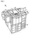
- Fig. 1 is a perspective view showing the appearance of a photocopier of one embodiment of the present invention.
- Fig. 2 is a front cross sectional view of the photocopier of Fig. 1.
- Fig. 3 is a block diagram of an electronic circuitry of the photocopier shown in Fig. 1
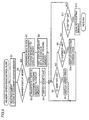
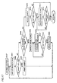
- Fig. 4 is a flow chart for display mode switching process.
- Fig. 5 is a flow chart for a specific example of step S108 in Fig. 4.
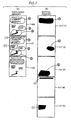
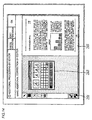
- Fig. 6 shows an example of the content of document reading memory 109 and the read document.
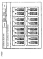
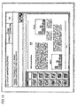
- Fig. 7 illustrates a specific example of the content of display memory 114 and content stored in editing memory 117.
- Fig. 8 shows an image plane for the user to select the relationship between a color of a marker and the process corresponding to the color.
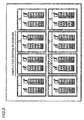
- Fig. 9 shows the relationship between the printed-out color of the marker and the process corresponding to the color.
- Fig. 10 shows an image plane for changing the relationship between the color of the marker and the process corresponding to the color.
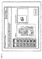
- Fig. 11 shows an image plane for urging the user to set the documents.
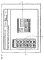
- Fig. 12 shows an image plane on which the read document is displayed.
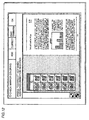
- Fig. 13 shows an image plane for urging instruction from the user for copying.
- Fig. 14 shows an image plane for adding to or correcting the instruction by the marker on the display.
- Fig. 15 shows an image plane in a state where a document laid to be longer in the lateral direction is read.
- Fig. 16 shows an image plane for adding to or correcting the instructions by the marker in the case where a document laid to be longer in the lateral direction is read.
- Fig. 17 is a flow chart for a process in the editing operation routine (S107) of Fig. 4.
- Fig. 18 is a flow chart for a process in the corrected and changed area displaying routine (S10) of Fig. 5.
- a color photocopier 100 includes an auto document feeder (or ADF) 200 for conveying a large amount of documents successively onto a platen and for discharging them automatically from the platen out of the machine after their images are read, a sorter 400 for sorting the paper for photocopying, a film projector 500 for copying an image from a film document, a screen editor 600 characteristic in the photocopier according to the present embodiment, and a printer controller 700 for using this photocopier as a color printer by connecting it to a personal computer or an EWS (workstation).
- ADF auto document feeder
- Screen editor 600 includes a liquid crystal display (LCD) 115 on which a menu for various operations is displayed for giving instructions of operations to the user.
- LCD liquid crystal display
- a transparent tablet is stacked for detecting the coordinates designated by the user, and by an input by the user with a pen 800, the coordinates on color LCD 115 can be input directly to the apparatus.
- Fig. 2 is a cross sectional view for illustrating the mechanism of the color photocopier shown in Fig. 1.
- the photocopier is generally comprised of image reader portion 30 and printer portion 20. Each of these portions will be described in the following.
- Image reader portion 30 includes a platen 31 for stacking a document thereon, a scanner 32 for scanning the document with exposure light, an image sensor (CCD) 201 for sensing the reflected light from the document, a image signal processing portion 330 for processing signals from image sensor 201, a print head (PH) controlling portion 335 for providing a control signal to the printer portion in accordance with the signal from image signal processing portion 330, and a pulse motor 35 for driving scanner 32.
- CCD image sensor
- PH print head
- the image of the document placed on platen 31 is scanned with exposure light by scanner 32, and the light reflected from the image is photoelectrically converted by image sensor 201.
- the photoelectrically converted signal is subjected to a predetermined process at image signal processing portion 330 so as to produce digital image data to drive laser diode.
- the produced digital image data is transmitted to print head controlling portion 335.
- Printer portion 20 is generally formed of an image creating portion, a developing unit portion, and a paper processing portion. Details thereof are given separately in the following.
- the image creating portion includes a laser device 21 driven in accordance with the digital image data transmitted from image reader portion 30, a photosensitive drum 4 for writing electrostatic latent image, a developing unit 6 for developing by a toner, a transfer drum 10 for transferring the image onto the surface of the paper, and a drum driving motor 22 for driving the photosensitive drum and the transfer drum.
- Laser device 21 is driven by the input digital image data and the like. Laser device 21 being driven causes formation of electrostatic latent image on the surface of photosensitive drum 4. The electrostatic latent image is toner-developed by developing unit 6, and is transferred onto the surface of the paper for printing placed on the transfer drum.
- photosensitive drum 4 and transfer drum 10 are driven in synchronization by driving motor 22.
- Developing unit 6 includes a magenta developer 6M for development by a magenta toner, a cyan developer 6C for development by a cyan toner, a yellow developer 6Y for development by a yellow toner, a black developer 6K for development by a black toner, four toner hoppers for supplying the toner of the corresponding color to each of the developers, and a developing unit motor 61 for moving developing unit 6 in a vertical direction.
- the paper processing portion includes housing cassettes 42 to 44 for putting in the papers for printing, and an intermediate housing portion 50 for temporarily putting in the papers.
- a paper drawn out from any one of the housing cassettes 42 to 44 or supplied from intermediate housing portion 50 is conveyed to transfer drum 10 by a group of conveying rollers and is rolled onto transfer drum 10. Thereafter, toner images (of 4 colors at most) on photosensitive drum 4 are successively transferred onto the paper.
- the paper on which images are transferred is then separated from the transfer drum 10, subjected to image fixation by a fixing device 48, and is discharged at a discharge tray 49.
- the apparatus is provided with a timing roller pair 45 for taking resist timing when the paper is conveyed, and a conveying belt 47.
- the above described group of rollers, conveying belt 47 and the like are driven by a main motor 41.
- transfer drum 10 a tip chuck claw for chucking the tip of the paper, an adsorption charger 11 for electrostatical adsorption of the paper to transfer drum 10, a paper clamping roller 12 for clamping the paper, a transfer charger 14 for causing the toner image appearing on the photosensitive drum to be sucked and transferred onto the paper, dischargers 16, 17 for discharging from the transfer drum to separate the paper, and a separation claw for peeling off the paper from the transfer drum.
- a tip chuck claw for chucking the tip of the paper
- an adsorption charger 11 for electrostatical adsorption of the paper to transfer drum 10
- a paper clamping roller 12 for clamping the paper
- a transfer charger 14 for causing the toner image appearing on the photosensitive drum to be sucked and transferred onto the paper
- dischargers 16, 17 for discharging from the transfer drum to separate the paper
- a separation claw for peeling off the paper from the transfer drum.
- a conveying route switching portion 54 is further disposed. By conveying route switching portion 54, selection is made on whether the conveyed paper is put in intermediate housing portion 50 after switch-back conveyance with an inversion device 51 or is put directly into intermediate housing portion 50.
- This selection is made in order to select whether the image is transferred on the same side of the paper on which printing is done already when the paper supplied from intermediate housing portion 50 is conveyed again to the transfer drum (a mode in which such transfer is performed being referred to as "image overlapping mode"), or is transferred on the rear side (in a mode similarly referred to as "both-sides copying mode").
- a reference location sensor 13 for detecting the reference location of the transfer drum, and an actuator plate 13a for actuating the reference location sensor are further disposed.
- Fig. 3 is a block diagram of an electronic circuitry for image processing provided to the photocopier of Fig. 1.
- the electronic circuitry for image processing includes an image reader (hereinafter also referred to as "IR" and which corresponds to image reader portion 30 in Fig. 2.) 30, a mono-color processing portion 102 for performing mono-color processing in which the image data (8 bits for each of RGB) obtained by IR 30 are replaced by a mono-color image data, a color conversion processing portion 103 for color conversion process in which image data of a specific color in the signals output from mono-color processing portion 102 are replaced by another color, an NP inversion processing portion 104 for inverting the NP (negative/positive) of the signal output from color conversion processing portion 103, an erase processing portion 105 for partially erasing the signals output from NP inversion processing portion 104, an image processing portion 106 for other image processes, and a printer 107 (printer portion 20 in Fig. 2) for printing out the image data output from image processing portion 106.
- IR image reader
- a mono-color processing portion 102 for performing mono-color processing in which the image data (8 bits for each of RGB
- the circuitry includes, as a block for editing, a binary conversion processing portion 108 for rendering the image data output from IR 30 into binary data, a document reading memory 109 for storing the binary image data separated into data of each of the colors including black, red, green and blue, a control CPU 110 for controlling the read image and the output image, a display memory 114 for recording the content of the data displayed on color LCD 115, color LCD 115, a pen input tablet 116 loaded on color LCD 115, an editing memory 117 employed for editing the image data consisting of memory for eight image planes, a work memory 118 of memory for two image planes forming a working area, and an editing function decoder 119 for controlling which of mono-color processing portion 102, color conversion processing portion 103, NP inversion processing portion 104, erase processing portion 105 would be made effective in accordance with data recorded in editing memory 117.
- Control CPU 110 includes an image reduction processing portion 111 for reducing the size of the image to display the read document on color LCD, an editing function set processing portion 112 for setting the editing function in accordance with the coordinates data input from the pen input tablet, and a drawing processing portion 113 for drawing the outline of the area to be edited also in accordance with the input coordinates data.
- the image data read by IR 30 is displayed on color LCD 115 via binary conversion processing portion 108, document reading memory 109, control CPU 110, and display memory 114.
- the image data read from IR 30 is output to printer 107 via mono-color processing portion 102, color conversion processing portion 103, NP inversion processing portion 104, erase processing portion 105 and image processing portion 106.
- the digital image data output from IR 30 is rendered into binary data by binary conversion processing portion 108.
- the digital image data is a full-color image data of 8 bits, 400 DPI (dot-per-inch) for each of R, G, B. Since a large memory capacity is required to store these data in the memory, the digital image data output from IR 30 is rendered into binary data by binary conversion processing portion 108 and has its resolution lowered from 400 DPI to 100 DPI. In this way, amount of information is reduced.
- Document reading memory 109 is formed of a structure including four planes. One of them is a plane of memory for the color black. The plane of memory for black stores the black portion of the document image (that is, the monotone image itself). The remaining three planes are for red, green and blue, and these three planes (3 bits) can indicate information for eight colors.
- the planes of memory for red, green and blue stores colored figures indicated by color markers of up to six colors except for white and black.
- image data stored in image reading memory 109 is sent to image reduction processing portion 111 inside control CPU 110 so as to reduce the resolution further.
- This reduction in resolution is performed because, while the image data in document reading memory 109 has a resolution of 100 DPI, the image displayed by color LCD 115 is about 30 to 50 DPI (the resolution differing depending on the size of the image to be displayed), such that further reduction in the size of the image is required.
- the image data reduced by image reduction processing portion 111 is stored in display memory 114.
- the image data stored in display memory 114 is directly displayed on color LCD 115.
- the user can perform the operation in an interactive manner owing to operation menu being displayed on color LCD 115 in accordance with the coordinates data input by pen input tablet.
- operation menu being displayed on color LCD 115 in accordance with the coordinates data input by pen input tablet.
- the operator can select a desired mode from hierarchically formed modes.
- editing function set processing portion 112 process is performed in an image editing mode (of process according to the color of the marker) determined by the user.
- a setting signal is transmitted from editing function set processing portion 112 to mono-color processing portion 102, color conversion processing portion 103, NP inversion processing portion 104 and erase processing portion 105, thereby performing various types of operations to the digital image data output from IR 30.
- drawing processing portion 113 process is performed to image editing area (that is, the area encircled by the marker) determined by operation by the user.
- Drawing processing portion 113 sets the edited area of the image using editing memory 117 and work memory 118.
- the eight planes included in editing memory 117 each corresponds to one editing function (image editing mode), respectively. On each of these planes of the editing memory, a figure is drawn in which the area specified by the user is colored completely. More specifically, only the area of the completely colored figure recorded in editing memory 117 is subjected to image editing.
- Editing function decoder 119 inputs an area signal (also referred to as editing area valid signal) according to the figure recorded in these planes of editing memories 117, and in accordance with the input area signal, determines which of the processing portions among mono-color processing portion 102, color conversion processing portion 103, NP inversion processing portion 104 and erase processing portion 105 is allocated.
- area signal also referred to as editing area valid signal
- Editing function decoder 119 outputs a valid signal for allowing editing function required for the edited area needed for the editing processing portions allocated.
- signal is output to editing function decoder 119 in accordance with area signal indicating inside and outside the edited area developed by the editing memory 117, such that valid/invalid is set for each of the pixels and process is carried on so that appropriate setting of the edited area is possible as specified by the user.
- work memory 118 of two planes is employed as memory for working upon drawing process to editing memory 117.
- the data subjected to image processing is output onto the paper as a color image according to electrostatic latent image scheme by printer 107.
- the image of the area encircled by the marker is, after the document is read by the image reader of the photocopier, edited as set corresponding to the color of the marker having that color.
- hatching is done on the image within the area encircled by the red marker
- color editing e. g., to render the image into blue image
- reduction in size is performed on the image in the area encircled by the blue marker.
- the document is read by image reader 30 and rendered into binary data by binary conversion processing portion 108. Thereafter, the data are stored in document reading memory 109.
- planes 109R, 109G and 109B where red, green and blue data are to be stored respectively, the shapes of the markers on the document themselves are stored. That is, plane 109R stores the shape of the area encircled by the red marker, plane 109G stores the shape of the area encircled by the green marker, and plane 109B stores the shape of the area encircled by the blue marker.
- the user can further add and correct the marker areas by input with a pen via pen input tablet 116. For example, the user can newly add areas (1) and (2) to the state shown in 114M of Fig. 7(A) to obtain image plane 114T, via tablet 116.
- the user can check the states before and after image editing process is performed, and in addition, can newly add/correct the marker areas for image editing process via tablet 116, and thus the apparatus is used more conveniently.
- Editing function decoder 119 recognizes these areas having their inner region colored completely, thereby identifies these areas as areas to be subjected to image editing, and outputs valid signals to each of the processing portions 102 to 105.
- the user can set the combination of the color of the marker used to mark the document and the process corresponding to that color of the marker in an arbitrary manner.
- the menu image plane for selecting the color of the marker and the process corresponding to that color is shown in Fig. 8. This menu image plane is displayed on color LCD 115.
- the operator can change the setting of the color of the marker and the corresponding editing process, which was difficult in the conventional art.
- the content of the editing process corresponding to the color of the marker shown in the right hand side of the above-described frame may be indicated by characters and the like.
- the relationship between the color of the marker and the corresponding editing process in the above-described frame can be changed and registered by the user arbitrarily.
- hatching process preset as the editing process corresponding to the red marker can be changed to a process of different editing content like color editing.
- a manipulation image plane shown in Fig. 10 is displayed on color LCD 115.
- the left frame of the plane shows the color of the marker which can be subjected to change of registration at left hand side LL
- the right hand side LR of the same frame shows the content of the editing process corresponding to that color. It shows the currently registered six colors of the markers and the current content of the editing processes corresponding to them respectively.
- a menu M for changing the setting is displayed. From the six colors LL of the markers indicated in the left portion of the frame and the content of the corresponding editing processes LR, the user can choose the ones which he or she wants to change, and make a selection from menu M to effect the change.
- the user indicates the "OK" button displayed at the upper-right corner of the image plane by the pen such that the set content are registered to the apparatus, and the manipulation image plane of Fig. 8 will display the newly registered content instead of the former content.
- the user can know the colors of the markers and the editing processes corresponding to those colors even when not being near the photocopier. Accordingly, it is possible for the user to conveniently perform the work of coloring the document by the marker at his or her desk and the like.
- the plane shown in Fig. 11 is displayed on color LCD 115.
- the image plane shows the image indicating the selected color of the marker and the corresponding content of the editing process at the left hand side, a sample of the coloring performed on the document at the center, and how the document should be set to the platen at the right hand side.
- the image plane displays the colors of the marker and the corresponding content of the editing process at its left, and the read document at its right.
- an image after being subjected to editing process by specification by the marker can also be displayed.
- the user can look at this document image after editing process so as to check to be sure that the editing with the specification by the marker is performed.
- the user can set the number of copies required by a ten key and press the start key so as to obtain the copies of the document image processed according to specification by the marker.
- the image plane shows an icon 201 at its left edge for various kinds of area specification, a menu 203 for specifying the editing process within the specified area at its right, and a read document 205 at the right hand side of the plane.
- the user can make changes and the like on the area and content of the editing process specified by the marker by pen input on color LCD 115 while checking the display thereof.
- the portion to be edited can be added by indicating an "add" button at the upper portion of the image plane by the pen.
- a read document image plane shown in Fig. 15 and a corrected document image plane shown in Fig. 16 are output.
- positions where an icon 201 for area specification and menu 203 for specifying editing mode depends on whether the read document is laid to be longer in vertical or lateral direction.
- the document can be displayed on color LCD 115 to be seen as large as possible.
- Fig. 4 is a flow chart for illustrating the process for automatically switching whether the document image is displayed on color LCD 115 or not.
- step S101 determination is made on whether automatic document feeder (ADF) is employed or not.
- ADF automatic document feeder
- step S101 determination is made at step S103 after pre-scanning at S102 on whether the number of areas in the document specified by the marker is small, for instance, five or less.
- NO at step S103 determination is made at step S104 on whether the number of colors used for the specification by the markers is small or not, for instance, less than three colors.
- step S104 When NO at step S104, that is, if the number of colors of the marker is small, process is progressed to a mode for displaying the document (S105). On the other hand, when YES at either of steps 103 or 104, process is progressed to a mode in which document is not displayed (S111).
- the marker specification performed is a simple one.
- manipulation by the user would be made troublesome, and therefore, documents are not displayed on LCD 115 when either one of the number of marker areas and the number of marker colors is small. It may be noted that the above-described numbers of the area and markers are arbitrary and can be variable by the user.
- step S106 determination is made on whether the mode for displaying the documents on color LCD 115 is performed.
- the image data read by the image reader at step S112 is not displayed on color LCD 115 and is stored in editing memory 117 via control CPU 110.
- step S110 the image data stored in editing memory 117 at step S110 is edited, and is copied by the printer. Thus, the copying is completed.
- step S106 operation control is performed for the editing process in accordance with the color and the area of the marker in the document at step S107. Thereafter, at step S108, operation control of the image in the memory is performed by the user. The process at step S108 will be described later.
- step S109 determination is made on whether instruction is given from the user to start printing (more specifically, whether the start key is pressed at Fig. 13) or not.
- steps S107 and S108 are repeated again.
- Fig. 17 shows a sub routine for editing operation controlling process of step S108 shown in Fig. 4.
- step S201 image plane of color LCD 115 is switched to the state shown in Fig. 8. Then, determination is made on whether the print key an the upper portion of the image plane of Fig. 8 is ON or not at step S202.
- print key is ON
- sample indicating the colors of the markers and the content of the editing processes corresponding to those colors is printed out as shown in Fig. 9 at step S203. Thereafter, process from step S201 is performed.
- step S202 determination is made on whether a registration change key at the upper portion of the image plane shown in Fig. 8 is ON or not at step S204.
- registration change key is ON
- the image plane of color LCD 115 is switched to the state shown in Fig. 10 at step S205.
- the process is halted, waiting for the OK button to be ON at step S207. Thereafter, when the OK button is turned ON, the changed content of the editing process is registered. Then, process from step S201 is performed.
- step S204 determination is made on whether one of the frames 1 to 8 in the image plane of Fig. 8 is selected at step S209.
- the ON key at the upper portion of the image plane of Fig. 8 is pressed after the user has selected frame 6 (step S210)
- the image plane of color LCD 115 is switched to the state shown in Fig. 11 (step S211).
- Fig. 5 is a flow chart for illustrating the specific example for the memory operation controlling process of step S108 shown in Fig. 4.
- document is read by the image reader at step S1.
- the read data is stored in document reading memory 109.
- step S2 determination is made on whether the marker display mode is selected in which the read document with markers thereon is displayed as it is, or the edited display mode is selected in which the document after being edited according to the marker is displayed.
- step S2 When it is determined that the marker display mode is selected at step S2 (YES at step S2), data corresponding to all of the colors are transferred from all of the planes 109K to 109B of the document reading memory to display memory 114. Accordingly, the read document image is displayed on color LCD 115 as it is. Then, the image plane of LCD 115 is switched to the state shown in Fig. 12 at step S4.
- step S5 determination is made on if there is addition of area indicated with the marker by the user. This is a determination on whether the add key at the upper portion of the image plane shown in Fig. 12 is ON/OFF.
- step S5 the displayed image plane is switched to the state shown in Fig. 14 at step S6, the user adds an area through icon 201, and the added area is displayed.
- step S6 After the process of step S6, the process from step S5 is carried on again.
- step S9 determination is made at step S9 on whether there should be any correction or change to the edited area specified by the marker at step S9 and the area added at step S6. In other words, ON/OFF of the correct key at the upper portion of the image plane shown in Figs. 12 and 13 is determined.
- step S10 of display process of corrected/changed area, with reference to Fig. 18.
- step S9 when it is determined that correct key is ON at step S9, the image plane of Fig. 12 which had been displayed on color LCD 115 is switched to the image plane of Fig. 14 (step S301). Then, determination is made on whether pen 800 is pressed onto any one point of the marker in the marker area displayed on tablet 116 (step S302). If pen 800 is pressed onto any one point on the marker, the user moves this pen 800 on tablet 116 while still pressing the tablet with the pen (step S303). Then, at step S304, detection is made on whether pen 800 is lifted up from the tablet or not. Thereafter, the coordinates of the point where pen 800 was lifted up from tablet 116 is recognized at CPU 110 and is stored (step S305).
- step S306 the entire coordinates of the marker area is corrected in accordance with this recognized coordinates of one arbitrary point of the marker.
- step S307 a new marker area is developed in display memory 114. Then, the process is returned.
- process is returned without allowing correction/change of the marker area.
- step S9 it is decided at step S11 whether the area specified by the marker at step S11 and area added, corrected or changed at steps S6, S10 are determined or not. More specifically, this determination is performed by the user indicating the "OK" region (Fig. 14) displayed on the image plane by the pen.
- step S11 process from step S6 is repeated.
- the photocopier in accordance with the present embodiment has the following effects.
Landscapes
- Engineering & Computer Science (AREA)
- Multimedia (AREA)
- Signal Processing (AREA)
- Editing Of Facsimile Originals (AREA)
- Control Or Security For Electrophotography (AREA)
Claims (15)
- Appareil de traitement d'image comprenant :un numériseur (30) pour numériser un document ayant une zone (R, V, B) qui est indiquée par une marque ;un détecteur (112, 113) pour détecter la position de la zone (R, V, B) à partir de données d'image obtenues par ledit numériseur (30) ;un moyen de traitement d'édition (102 à 105, 119) pour effectuer un traitement d'édition sur les données d'image à l'intérieur de la zone (R, V, B) ;un affichage (115) capable d'afficher des données d'image ayant la zone (R, V, B) qui est indiquée par la marque obtenue par ledit numériseur et les données d'image ayant effectuées le traitement d'édition ; etun moyen de correction de zone (116, 110) corrigeant la zone qui est indiquée par la marque en liaison avec les données d'image affichées sur ledit affichage (115) en corrigeant les coordonnées d'un point arbitraire de la marque.
- Appareil de traitement d'image selon la revendication 1, incluant, en outre, une imprimante (107) pour imprimer les données d'image ayant effectuées le traitement d'édition.
- Appareil de traitement d'image selon la revendication 1, dans lequel ledit traitement d'édition inclut le masquage, le rognage, et les traitements de conversion de couleur.
- Appareil de traitement d'image selon la revendication 1, incluant, en outre, un moyen de commutation d'affichage (110) pour commuter l'affichage sur ledit affichage (115), dans lequel ledit moyen de commutation d'affichage (110) effectue la commutation entre l'affichage des données d'image obtenues par le numériseur (30) et des données d'image ayant effectuées le traitement d'édition.
- Appareil de traitement d'image selon la revendication 1, incluant, en outre, un moyen de détermination (110) pour déterminer le nombre de zones qui sont indiquées par des marques disposées sur un document.
- Appareil de traitement d'image selon la revendication 5, dans lequel ledit appareil de traitement d'image interdit l'affichage des données d'image sur ledit affichage (115) lorsque le nombre de zones (R, V, B) est plus petit qu'un nombre prescrit.
- Appareil de traitement d'image selon la revendication 1, incluant, en outre, un moyen de détermination (110) pour déterminer le nombre de couleurs de la marque disposée sur le document.
- Appareil de traitement d'image selon la revendication 7, dans lequel ledit appareil de traitement d'image interdit l'affichage des données d'image sur ledit affichage (115) lorsque le nombre de couleurs de la marque est plus petit qu'un nombre prescrit.
- Appareil de traitement d'image selon la revendication 1, incluant, en outre, un moyen de mémoire (110) pour mémoriser une pluralité de couleurs des marqueurs pour délivrer la marque et le contenu des traitements d'édition préétablis correspondant aux couleurs des marqueurs respectivement de manière correspondante, dans lequel le contenu des traitements d'édition préétablis correspondant aux couleurs des marqueurs est respectivement différent pour chaque marqueur.
- Appareil de traitement d'image selon la revendication 9, incluant, en outre, un moyen de changement (116, 110) pour changer la corrélation entre la pluralité des couleurs des marqueurs et le contenu des traitements d'édition préétablis pour les marqueurs respectifs.
- Appareil de traitement d'image selon la revendication 1, incluant, en outre, un dispositif d'avancée de document (200) pour décharger le document après qu'il soit positionné sur une plaque (31) et a son image lue par ledit numériseur (30).
- Appareil de traitement d'image selon la revendication 11, dans lequel ledit appareil de traitement d'image interdit l'affichage des données d'image sur ledit affichage (115) lorsque ledit dispositif d'avancée de document (200) est employé.
- Appareil de traitement d'image selon la revendication 1, incluant, en outre, un moyen d'ajout de zone (116, 110) pour ajouter une zone qui doit être éditée depuis ledit affichage (115) sur lequel les données d'image sont affichées.
- Appareil de traitement d'image selon la revendication 13, dans lequel ledit moyen d'ajout de zone (116, 110) inclut une tablette (116) disposée sur ledit affichage (115), et l'ajout de la zone qui doit être éditée est possible en pressant sur cette tablette (116).
- Appareil de traitement d'image selon la revendication 1, dans lequel ledit moyen de correction de zone (116, 110) inclut une tablette (116) disposée sur ledit affichage (115) et la correction de la zone qui doit être éditée est possible en pressant sur cette tablette (116).
Applications Claiming Priority (3)
| Application Number | Priority Date | Filing Date | Title |
|---|---|---|---|
| JP29421295 | 1995-11-13 | ||
| JP294212/95 | 1995-11-13 | ||
| JP29421295A JP3334025B2 (ja) | 1995-11-13 | 1995-11-13 | 画像形成装置 |
Publications (3)
| Publication Number | Publication Date |
|---|---|
| EP0773667A2 EP0773667A2 (fr) | 1997-05-14 |
| EP0773667A3 EP0773667A3 (fr) | 1999-05-19 |
| EP0773667B1 true EP0773667B1 (fr) | 2003-02-05 |
Family
ID=17804788
Family Applications (1)
| Application Number | Title | Priority Date | Filing Date |
|---|---|---|---|
| EP96118138A Expired - Lifetime EP0773667B1 (fr) | 1995-11-13 | 1996-11-12 | Appareil de traitement d'images |
Country Status (4)
| Country | Link |
|---|---|
| US (2) | US6345118B1 (fr) |
| EP (1) | EP0773667B1 (fr) |
| JP (1) | JP3334025B2 (fr) |
| DE (1) | DE69626086T2 (fr) |
Families Citing this family (24)
| Publication number | Priority date | Publication date | Assignee | Title |
|---|---|---|---|---|
| DE69805555T2 (de) * | 1997-02-10 | 2003-01-16 | Fillfactory N.V., Mechelen | Verfahren zur Erzeugung eines Auslegesignals einer auf CMOS basierender Pixelstruktur und eine solche auf CMOS basierender Pixelstruktur |
| US6395019B2 (en) * | 1998-02-09 | 2002-05-28 | Trivascular, Inc. | Endovascular graft |
| JP2000153647A (ja) * | 1998-11-18 | 2000-06-06 | Canon Inc | 画像処理装置およびその方法 |
| DE19854241B4 (de) * | 1998-11-24 | 2014-03-06 | Siemens Aktiengesellschaft | Verfahren zum Darstellen von an einem Anzeigemonitor wiedergebbaren Bildern sowie Vorrichtung zum Verarbeiten und Wiedergeben digitaler Bilder |
| US6618170B1 (en) * | 1999-05-14 | 2003-09-09 | Xerox Corporation | User interface comprising hue shift control for color printing |
| US20030231367A1 (en) * | 2002-05-31 | 2003-12-18 | Angelica Quintana | Document image capture device with integrated document display screen |
| JP2004086810A (ja) * | 2002-08-29 | 2004-03-18 | Fuji Xerox Co Ltd | 画像形成システム、バックエンドプロセッサ |
| US20050097046A1 (en) | 2003-10-30 | 2005-05-05 | Singfield Joy S. | Wireless electronic check deposit scanning and cashing machine with web-based online account cash management computer application system |
| US7826664B2 (en) * | 2004-05-24 | 2010-11-02 | Xerox Corporation | Systems and methods for efficient manual windowing operation |
| US7379595B2 (en) * | 2004-05-24 | 2008-05-27 | Xerox Corporation | Manual windowing with auto-segmentation assistance in a scanning system |
| US20060044583A1 (en) * | 2004-08-25 | 2006-03-02 | Dainippon Screen Mfg. Co., Ltd. | Printing data processor, printing system, printing data correction method, inspection processing method and program |
| US20060082816A1 (en) * | 2004-10-15 | 2006-04-20 | Lexmark International, Inc. | Printer device and related method for handling print-and-hold jobs |
| US8619313B2 (en) * | 2005-10-28 | 2013-12-31 | Hewlett-Packard Development Company, L.P. | Scanning device with plural image capture zones on a platen |
| US8708227B1 (en) * | 2006-10-31 | 2014-04-29 | United Services Automobile Association (Usaa) | Systems and methods for remote deposit of checks |
| JP5114140B2 (ja) * | 2007-09-12 | 2013-01-09 | 株式会社リコー | 画像表示システム及び方法 |
| US20090073507A1 (en) * | 2007-09-18 | 2009-03-19 | Sharp Kabushiki Kaisha | Document reading apparatus and document reading system |
| US8650634B2 (en) * | 2009-01-14 | 2014-02-11 | International Business Machines Corporation | Enabling access to a subset of data |
| US8441702B2 (en) * | 2009-11-24 | 2013-05-14 | International Business Machines Corporation | Scanning and capturing digital images using residue detection |
| US8610924B2 (en) * | 2009-11-24 | 2013-12-17 | International Business Machines Corporation | Scanning and capturing digital images using layer detection |
| US20110122459A1 (en) * | 2009-11-24 | 2011-05-26 | International Business Machines Corporation | Scanning and Capturing digital Images Using Document Characteristics Detection |
| JP2011123740A (ja) * | 2009-12-11 | 2011-06-23 | Fujifilm Corp | 閲覧システム、サーバ、テキスト抽出方法及びプログラム |
| JP4856776B1 (ja) * | 2010-11-29 | 2012-01-18 | エピクロス株式会社 | 画像処理装置およびその方法 |
| JP6540280B2 (ja) * | 2015-06-30 | 2019-07-10 | ブラザー工業株式会社 | 画像処理装置およびコンピュータプログラム |
| US11030752B1 (en) | 2018-04-27 | 2021-06-08 | United Services Automobile Association (Usaa) | System, computing device, and method for document detection |
Citations (1)
| Publication number | Priority date | Publication date | Assignee | Title |
|---|---|---|---|---|
| US4740814A (en) * | 1987-01-09 | 1988-04-26 | Xerox Corporation | Preview system for an electrophotographic printing machine |
Family Cites Families (24)
| Publication number | Priority date | Publication date | Assignee | Title |
|---|---|---|---|---|
| US4538182A (en) | 1981-05-11 | 1985-08-27 | Canon Kabushiki Kaisha | Image processing apparatus |
| JPS5963864A (ja) * | 1982-10-05 | 1984-04-11 | Canon Inc | 画像処理装置 |
| GB8330869D0 (en) * | 1983-11-18 | 1983-12-29 | Centurfax Ltd | Page make-up system |
| JPS614061A (ja) * | 1984-06-18 | 1986-01-09 | Dainippon Screen Mfg Co Ltd | カラ−スキヤナを用いた切抜きマスク作成方法および装置 |
| US5259041A (en) | 1987-05-12 | 1993-11-02 | Konica Corporation | Image processing method and apparatus |
| EP0307948B1 (fr) * | 1987-09-18 | 1993-03-03 | Toppan Printing Co., Ltd. | Balayeur de contour |
| US4908716A (en) * | 1987-12-08 | 1990-03-13 | Ricoh Company, Ltd. | Image processing apparatus |
| US4837635A (en) | 1988-01-22 | 1989-06-06 | Hewlett-Packard Company | A scanning system in which a portion of a preview scan image of a picture displaced on a screen is selected and a corresponding portion of the picture is scanned in a final scan |
| JP2662429B2 (ja) * | 1988-11-14 | 1997-10-15 | キヤノン株式会社 | 画像編集装置 |
| US5162918A (en) * | 1989-01-13 | 1992-11-10 | Minolta Camera Kabushiki Kaisha | Copying apparatus with display of both document image and frame of document contour |
| JP2722119B2 (ja) | 1989-08-17 | 1998-03-04 | 株式会社ムラオ・アンド・カンパニー | スプールの残ラップ除去装置 |
| GB8921244D0 (en) | 1989-09-20 | 1989-11-08 | Hewlett Packard Co | Optical mixer |
| EP0423654A3 (en) | 1989-10-19 | 1992-07-08 | Konica Corporation | Colour image processing apparatus |
| DE69232653D1 (de) * | 1991-02-20 | 2002-07-25 | Canon Kk | Bildverarbeitungsgerät |
| JP2990306B2 (ja) * | 1991-05-14 | 1999-12-13 | 富士ゼロックス株式会社 | カラー画像記録装置のマーカドット検出方式 |
| JP3229370B2 (ja) * | 1991-06-07 | 2001-11-19 | キヤノン株式会社 | 画像形成装置および画像処理方法 |
| JPH0514630A (ja) | 1991-07-03 | 1993-01-22 | Minolta Camera Co Ltd | マーカー領域検出装置及び検出方法 |
| US5406389A (en) * | 1991-08-22 | 1995-04-11 | Riso Kagaku Corporation | Method and device for image makeup |
| JPH05145743A (ja) * | 1991-11-21 | 1993-06-11 | Ricoh Co Ltd | 画像形成装置 |
| JP3215137B2 (ja) * | 1992-01-24 | 2001-10-02 | 株式会社リコー | 遠隔会議用通信端末装置 |
| JPH05211600A (ja) | 1992-01-30 | 1993-08-20 | Canon Inc | 画像処理装置 |
| EP0585000A3 (en) * | 1992-08-21 | 1994-06-08 | Hitachi Ltd | A sheet processing apparatus, and a facsimile system incorporating such an apparatus |
| JPH06284270A (ja) * | 1993-03-29 | 1994-10-07 | Toshiba Corp | 画像形成装置 |
| JPH10257299A (ja) * | 1997-03-11 | 1998-09-25 | Minolta Co Ltd | 画像編集装置 |
-
1995
- 1995-11-13 JP JP29421295A patent/JP3334025B2/ja not_active Expired - Fee Related
-
1996
- 1996-11-12 DE DE69626086T patent/DE69626086T2/de not_active Expired - Lifetime
- 1996-11-12 EP EP96118138A patent/EP0773667B1/fr not_active Expired - Lifetime
- 1996-11-13 US US08/747,835 patent/US6345118B1/en not_active Expired - Lifetime
-
2001
- 2001-09-25 US US09/961,296 patent/US20020031282A1/en not_active Abandoned
Patent Citations (1)
| Publication number | Priority date | Publication date | Assignee | Title |
|---|---|---|---|---|
| US4740814A (en) * | 1987-01-09 | 1988-04-26 | Xerox Corporation | Preview system for an electrophotographic printing machine |
Also Published As
| Publication number | Publication date |
|---|---|
| JPH09138613A (ja) | 1997-05-27 |
| US6345118B1 (en) | 2002-02-05 |
| DE69626086T2 (de) | 2003-11-20 |
| US20020031282A1 (en) | 2002-03-14 |
| EP0773667A3 (fr) | 1999-05-19 |
| EP0773667A2 (fr) | 1997-05-14 |
| JP3334025B2 (ja) | 2002-10-15 |
| DE69626086D1 (de) | 2003-03-13 |
Similar Documents
| Publication | Publication Date | Title |
|---|---|---|
| EP0773667B1 (fr) | Appareil de traitement d'images | |
| US5475475A (en) | Image forming apparatus and method in which image of a plurality of originals are formed at different positions of one recording sheet | |
| EP0920188B1 (fr) | Appareil de traitement d'image | |
| US6963721B2 (en) | Image forming apparatus having function of automatically selecting one of sheet feeders, method of controlling the image forming apparatus and storage medium | |
| US5875035A (en) | Image processing device with original image determination means | |
| JPH08314329A (ja) | カラー画像形成装置 | |
| US5937233A (en) | Image editing apparatus that edits by detecting marker applied to original | |
| US6078767A (en) | Image processing apparatus capable of easily designating image to be edited | |
| JP2905655B2 (ja) | 画像処理装置 | |
| US6809742B1 (en) | Image editing device permitting user to register desired patterns | |
| JPH11220614A (ja) | 画像編集装置 | |
| US6002404A (en) | Image editing device for processing image data | |
| JP3539079B2 (ja) | 画像編集装置 | |
| JP3671523B2 (ja) | 画像編集装置 | |
| JPH06164893A (ja) | 画像処理装置 | |
| JP3603550B2 (ja) | 画像処理装置 | |
| JPH1053338A (ja) | マルチトレイのトレイ選択装置 | |
| JP3381468B2 (ja) | 画像処理装置 | |
| JPH09224149A (ja) | 画像形成装置 | |
| JPH0968896A (ja) | ディジタルカラー画像形成装置 | |
| JPH04136870A (ja) | 画像形成装置 | |
| JPH03139974A (ja) | 画像処理装置 | |
| JPH05130398A (ja) | フルカラー作像装置 | |
| JPH1173062A (ja) | 機能設定用シート及びこれを用いた画像処理装置 | |
| JPH02296263A (ja) | 画像処理装置における操作方法 |
Legal Events
| Date | Code | Title | Description |
|---|---|---|---|
| PUAI | Public reference made under article 153(3) epc to a published international application that has entered the european phase |
Free format text: ORIGINAL CODE: 0009012 |
|
| AK | Designated contracting states |
Kind code of ref document: A2 Designated state(s): DE FR GB |
|
| PUAL | Search report despatched |
Free format text: ORIGINAL CODE: 0009013 |
|
| AK | Designated contracting states |
Kind code of ref document: A3 Designated state(s): DE FR GB |
|
| 17P | Request for examination filed |
Effective date: 19991021 |
|
| 17Q | First examination report despatched |
Effective date: 20000724 |
|
| GRAH | Despatch of communication of intention to grant a patent |
Free format text: ORIGINAL CODE: EPIDOS IGRA |
|
| GRAH | Despatch of communication of intention to grant a patent |
Free format text: ORIGINAL CODE: EPIDOS IGRA |
|
| GRAA | (expected) grant |
Free format text: ORIGINAL CODE: 0009210 |
|
| AK | Designated contracting states |
Designated state(s): DE FR GB |
|
| REG | Reference to a national code |
Ref country code: GB Ref legal event code: FG4D |
|
| REF | Corresponds to: |
Ref document number: 69626086 Country of ref document: DE Date of ref document: 20030313 Kind code of ref document: P |
|
| ET | Fr: translation filed | ||
| PLBE | No opposition filed within time limit |
Free format text: ORIGINAL CODE: 0009261 |
|
| STAA | Information on the status of an ep patent application or granted ep patent |
Free format text: STATUS: NO OPPOSITION FILED WITHIN TIME LIMIT |
|
| 26N | No opposition filed |
Effective date: 20031106 |
|
| PGFP | Annual fee paid to national office [announced via postgrant information from national office to epo] |
Ref country code: DE Payment date: 20121107 Year of fee payment: 17 Ref country code: FR Payment date: 20121130 Year of fee payment: 17 |
|
| PGFP | Annual fee paid to national office [announced via postgrant information from national office to epo] |
Ref country code: GB Payment date: 20121107 Year of fee payment: 17 |
|
| GBPC | Gb: european patent ceased through non-payment of renewal fee |
Effective date: 20131112 |
|
| REG | Reference to a national code |
Ref country code: FR Ref legal event code: ST Effective date: 20140731 |
|
| PG25 | Lapsed in a contracting state [announced via postgrant information from national office to epo] |
Ref country code: DE Free format text: LAPSE BECAUSE OF NON-PAYMENT OF DUE FEES Effective date: 20140603 |
|
| REG | Reference to a national code |
Ref country code: DE Ref legal event code: R119 Ref document number: 69626086 Country of ref document: DE Effective date: 20140603 |
|
| PG25 | Lapsed in a contracting state [announced via postgrant information from national office to epo] |
Ref country code: FR Free format text: LAPSE BECAUSE OF NON-PAYMENT OF DUE FEES Effective date: 20131202 Ref country code: GB Free format text: LAPSE BECAUSE OF NON-PAYMENT OF DUE FEES Effective date: 20131112 |