EP0774203B1 - Konstruktion mit einem Gerät zum Melken von Tieren - Google Patents
Konstruktion mit einem Gerät zum Melken von Tieren Download PDFInfo
- Publication number
- EP0774203B1 EP0774203B1 EP96203145A EP96203145A EP0774203B1 EP 0774203 B1 EP0774203 B1 EP 0774203B1 EP 96203145 A EP96203145 A EP 96203145A EP 96203145 A EP96203145 A EP 96203145A EP 0774203 B1 EP0774203 B1 EP 0774203B1
- Authority
- EP
- European Patent Office
- Prior art keywords
- sensor
- teat cup
- construction
- teat
- carrier
- Prior art date
- Legal status (The legal status is an assumption and is not a legal conclusion. Google has not performed a legal analysis and makes no representation as to the accuracy of the status listed.)
- Expired - Lifetime
Links
- 238000010276 construction Methods 0.000 title claims description 34
- 241001465754 Metazoa Species 0.000 title claims description 30
- 210000002445 nipple Anatomy 0.000 claims description 116
- QSHDDOUJBYECFT-UHFFFAOYSA-N mercury Chemical compound [Hg] QSHDDOUJBYECFT-UHFFFAOYSA-N 0.000 claims description 6
- 229910052753 mercury Inorganic materials 0.000 claims description 6
- 239000008267 milk Substances 0.000 description 22
- 210000004080 milk Anatomy 0.000 description 22
- 235000013336 milk Nutrition 0.000 description 22
- 230000008878 coupling Effects 0.000 description 6
- 238000010168 coupling process Methods 0.000 description 6
- 238000005859 coupling reaction Methods 0.000 description 6
- 230000010349 pulsation Effects 0.000 description 6
- 210000003608 fece Anatomy 0.000 description 4
- 230000003213 activating effect Effects 0.000 description 2
- 239000000463 material Substances 0.000 description 2
- 239000000969 carrier Substances 0.000 description 1
- 230000000694 effects Effects 0.000 description 1
Images


Classifications
-
- A—HUMAN NECESSITIES
- A01—AGRICULTURE; FORESTRY; ANIMAL HUSBANDRY; HUNTING; TRAPPING; FISHING
- A01J—MANUFACTURE OF DAIRY PRODUCTS
- A01J5/00—Milking machines or devices
- A01J5/017—Automatic attaching or detaching of clusters
- A01J5/0175—Attaching of clusters
Definitions
- the invention relates to a construction including an implement for milking animals, provided with one or more milking parlours where an animal can be milked, said implement comprising a sensor, which supplies a signal when a teat cup, e.g. because it is kicked off from a teat, gets out of order.
- the invention further relates to a construction including an implement for milking animals, provided with one or more milking parlours where an animal can be milked, said implement comprising a sensor, which supplies a signal when a teat cup, e.g. because it is kicked off from a teat, gets out of order, said teat cup being detachably disposed on a carrier, said sensor being provided at the place where the teat cup is carried or near thereto.
- the invention also relates to a construction including an implement for milking animals, provided with one or more milking parlours where an animal can be milked, said implement comprising a sensor, which supplies a signal when a teat cup, e.g. because it is kicked off from a teat, gets out of order, said teat cup being detachably disposed on a carrier, said sensor being provided at the place where the teat cup is carried or near thereto.
- WO 96/17509 Such constructions are known from the International patent application WO 96/17509 which forms prior art under Art. 54(3) EPC.
- the construction as described in WO 96/17509 comprises a milking machine having a milking line connected to the teat cups and having an air suction line running with one end into the teat cup or into a milking line.
- a sensor is incorporated in the air suction line for the purpose of ascertaining the air pressure. When the teat cup is kicked off from the teat by the animal this can be detected by the air pressure sensor.
- the present invention provides constructions which are different from the one described in WO 96/17509, while still maintaining the possibility of supplying a signal when a teat cup, e.g. because it is kicked off from a teat, gets out of order.
- the invention relates to a construction including an implement for milking animals, provided with one or more milking parlours where an animal can be milked, said implement comprising a sensor, which supplies a signal when a teat cup, e.g. because it is kicked off from a teat, gets out of order, characterized in that the sensor is provided on the teat cup.
- the sensor is constituted by a mercury switch. Said mercury switch is preferably disposed on the casing of a teat cup and supplies a signal as soon as the teat cup is pivoted over a pre-fixed angle of e.g.
- the computer Upon receiving a signal from the sensor provided on the teat cup, the computer supplies a signal to the withdrawing member, in order that the relevant teat cup is withdrawn to the carrier as quickly as possible and thus is prevented from falling onto the floor.
- the invention relates to a construction including an implement for milking animals, provided with one or more milking parlours where an animal can be milked, said implement comprising a sensor, which supplies a signal when a teat cup, e.g. because it is kicked off from a teat, gets out of order, said teat cup being detachably disposed on a carrier, said sensor being provided at the place where the teat cup is carried or near thereto, characterized in that the sensor is disposed near a withdrawing member, by means of which the teat cup can be drawn towards the carrier, and the sensor supplies a signal to a computer when the withdrawing member has entirely withdrawn.
- the operating person can verify, on the basis of computer data, whether a teat cup has got out of order.
- the sensor supplies no signal after the computer has supplied a signal to the withdrawing member to withdraw the teat cup, the computer ascertains that the relevant teat cup has not been withdrawn onto the carrier and consequently has got out of order.
- the withdrawing member comprises a flexible element, such as a cord, which is connected with one end with a teat cup and with the other end with a withdrawing element, such as a cylinder.
- the sensor is activated by the end of a piston rod of the cylinder of the withdrawing member.
- the sensor When a teat cup is withdrawn onto the carrier in a proper manner, the sensor supplies a signal indicating that the withdrawal has been carried out correctly. When the end of the piston rod does not activate the sensor, this means that the relevant teat cup has not returned to the carrier and consequently has got out of order.
- the sensor is constituted by a micro-switch. By means of the sensor on the carrier and/or the sensor near the piston rod, it can be verified whether the withdrawal of the teat cup has been carried out correctly.
- the invention relates to a construction including an implement for milking animals, provided with one or more milking parlours where an animal can be milked, said implement comprising a sensor, which supplies a signal when a teat cup, e.g. because it is kicked off from a teat, gets out of order, said teat cup being detachably disposed on a carrier, said sensor being provided at the place where the teat cup is carried or near thereto, characterized in that the sensor is disposed in a conical seat of the carrier, and the bottom side of the teat cup is conical so as to correspond to the seat.
- the operating person can verify, on the basis of computer data, whether a teat cup has got out of order. When the teat cup has accidentally got out of the conical seat and/or has not returned thereto, this is ascertained by means of the sensor and a computer, whereafter it can be pointed out to an operating person that the relevant teat cup has got out of order.
- the implement comprises a vacuum sensor capable of determining the vacuum in the vacuum line of the teat cup and which supplies a signal to the computer when a teat cup is disconnected from a teat, whereafter the computer supplies a signal to the shutting off means which shut off the vacuum line, in order that the vacuum in the teat cup is removed.
- the aforementioned sensors are in particular advantageously applicable in an automatic milking implement including a milking robot.
- the implement comprises a milking robot, by means of which teat cups can automatically be connected from the carrier to the teats of an animal to be milked, respectively be disconnected therefrom, and be brought back to the carrier by means of the withdrawing member.
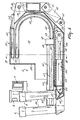
- Figure 1 shows in plan view an implement for milking animals, including a milk box 1 provided with an entrance door 2, an exit door 3 and a feed trough 4. At the opposite sides of the entrance door 2 and the exit door 3, beside the fencing of the milk box 1, there is arranged a milking robot 5, by means of which teat cups 6 can automatically be connected to the teats of an animal 7, respectively be disconnected therefrom.
- a second robot arm 8 provided at its end with a detector 9, by means of which the position of the teats of an animal to be milked can be determined.
- the detector 9 is designed as a laser making a scanning movement in a horizontal plane.
- an other type of detector such as an ultrasonographic sensor.
- the milking robot 5 and the second robot arm 8 can be active independently of each other.
- the collecting member 10 comprises a gutterlike housing 11 which, near its lower side, is provided with a lug 12 which is pivotably connected about a horizontal shaft 13 with a second lug 14. Thereby the first horizontal shaft 13 extends in the longitudinal direction of the milk box 1.
- the second lug 14 is further pivotable about a second horizontal shaft 15, which is disposed in a U-shaped profile 16 transversely to the longitudinal direction of the milk box 1.
- the U-shaped profile 16 is fastened on the floor 17 of the milk box 1.
- a first cylinder 18 extending in the longitudinal direction of the milk box 1.
- One end of the first cylinder 18 is pivotably connected with the second lug 14 about a third horizontal shaft 19 and the other end thereof is pivotably connected with the floor 17 about a fourth horizontal shaft 20.
- the third horizontal shaft 19 and the fourth horizontal shaft 20 both extend transversely to the longitudinal direction of the milk box 1 and are both disposed in U-shaped profiles.
- a third lug 21 to which, pivotably about a fifth horizontal shaft 22 extending in the longitudinal direction of the milk box 1, there is attached a second cylinder 23. With its other end, the second cylinder 23 is connected, pivotably about a sixth horizontal shaft 24, also extending in the longitudinal direction of the milk box 1, with the second lug 14.
- the collecting member 10 can be pivoted about the second horizontal shaft 15 in the longitudinal direction of the milk box 1 and, by means of the second cylinder 23, the collecting member 10 can be pivoted about the first horizontal shaft 13 in the transverse direction of the milk box 1.
- the gutterlike housing 11 comprises a triangular bottom 25 made of a plate, one point of which extends obliquely downwards from the cow. Thereby said point of the triangular bottom 25 debouches over a grid floor 26 provided in the right rear angle of the milk box 1. Under the grid floor 26 there is located a dung discharge gutter 27 connected to a (non-shown) dung cellar. The horizontally extending upper edge of the triangular bottom 25 extends transversely to the milk box 1 and is situated at a height of approximately 1.25 m.
- the gutterlike housing 11 furthermore comprises, seen in rear view, a quadrangular back wall 28 made of a plate.
- the first side 29 of the back wall 28 includes an angle of approximately 140° with the horizontal line and the further side 30 includes an angle of approximately 90° with the first side 29.
- the further side 30 comprises near its upper end a bent part 31 including an angle of approximately 30° with the other part of the further side 30.
- the collecting member 10 is additionally provided with a (non-shown) cow tracking device, by means of which the milking robot 5 can be post-controlled when the animal 7 moves in the longitudinal direction of the milk box 1.
- the end of the milking robot 5 is shown in detail.
- the teat cups 6 rest on a carrier 32 which is pivotable about a vertical shaft 33.
- the carrier 32 comprises four juxtaposed units 34 each carrying near an end a teat cup 6.
- the units 34 each comprise a boxlike housing 35, which is pivotable about a horizontal shaft 36.
- the horizontal shaft 36 is disposed on an L-shaped box girder 37 of the milking robot 5.
- the unit 35 is provided with two lugs 39 which are pivotably disposed about the horizontal shaft 36.
- Each of the units 34 is individually pivotable about the horizontal shaft 36 by means of a cylinder 40.
- the cylinder 40 is connected with one end, by means of lugs 41, with the L-shaped box girder 37 and, with the other end, by means of lugs 42, with the boxlike housing 35.
- the cylinder 40 may also be designed as a step motor.
- the milk tubes 43 and the pulsation tubes 44 of the teat cups 6 are accommodated.
- the milk tubes and pulsation tubes 43, 44 are located approximately in a circular loop in the boxlike housings 35 ( Figure 5).
- a first part 45 of the milk tubes and pulsation tubes 43, 44 extends from a teat cup 6 in a vertical plane and a second part 46 of the tubes comprises a loop-shaped part 46 located in the vertical plane.
- the first and second part 45, 46 respectively of the tubes 43, 44 are connected to each other by means of a coupling block 47.
- the first part 45 of the tubes is connected to connecting nipples 48, which are arranged one below the other at one side of the coupling block 47, whereas the second part 46 of the tubes is connected to connecting nipples 49, which are disposed next to each other at the other side of the coupling block 47.
- the coupling block 47 By means of the coupling block 47, there is obtained a kink-free connection between the first part 45, where the tubes are located above each other, and the second part 46, where the tubes are located next to each other.
- Both in the first and second part 45, 46 of the tubes the jackets of the milk tubes and pulsation tubes 43, 44 are interconnected.
- the jacket of the first part 45 of the tubes is made of a relatively rigid material, so that the teat cup 6 is prevented from falling down too easily.
- the second part 46 of the tubes 43, 44 is made of a relatively flexible material.
- the other end of the second part 46 of the tubes is connected with a second coupling block 50, which is provided with two pairs of superposed connecting nipples 51, to which, on the one hand, the end of the second part 46 of the tubes is connected and, on the other hand, a pipelike milk line 52 and a pipelike pulsation line 53 are connected ( Figures 5, 6).
- the second coupling block 50 disposed in the left upper part of the boxlike housing 35, there is obtained a diversion of 180° for the milk-pulsation tube 43, 44.
- the pipelike milk line and the pipelike pulsation line 53 are situated next to each other.
- each boxlike housing 35 there is moreover disposed a withdrawing member 54, by means of which the teat cups 6 can be withdrawn towards the carrier 32.
- the withdrawing member 54 comprises a cylinder 55, arranged in the lower part of the boxlike housing 35.
- the withdrawing member 54 is additionally provided with a cord 56 which is connected with one end with the boxlike housing 35 and with the other end with a conical bottom side 57 of the teat cup 6.
- the cord 56 is further guided over a wheel 59 that is rotatably disposed at the end of the piston rod 58 of the cylinder 55.
- the piston rod 58 is entirely pulled out, whereby the wheel 59 touches a sensor 60, designed as a switch, which is disposed against a wall 61 of the boxlike housing 35.
- a sensor 60 designed as a switch, which is disposed against a wall 61 of the boxlike housing 35.
- the switch 60 By means of the switch 60 there can be recorded whether the cord 56 is entirely stretched so that the teat cup 6 rests on the carrier 32 in a proper manner.
- the switch 60 supplies a signal to the computer.
- the cylinder 55 is activated again and, when again no signal is supplied by the switch 60, the computer will give an error message which, by means of e.g. a radiophone, is passed on to an operating person.
- Each of the carriers 32 is provided near its end with a conical seat 62 corresponding to the conical bottom side 57 of the teat cup 6.
- the conical seat 62 is disposed in the carrier 32 in such a way that, when the lower end of the carrier 32 is located in a horizontal plane, a teat cup 6 put on the conical seat 62 takes a somewhat forwardly inclined position.
- the angle at which the teat cup 6 is positioned relative to the vertical line lies approximately between 3° and 10° and is preferably 5°.
- a sensor 63 For the purpose of verifying whether, by activating the withdrawing member 54, a teat cup 6 is put in the conical seat 62 in a proper manner, there is fitted in the conical seat 62 a sensor 63 recording whether the conical bottom side 57 of the teat cup 6 is correctly put in the conical seat 62.
- the sensor 63 may thereby be designed as a micro-switch or a conductivity sensor.
- a sensor 65 On the outer casing 64 of the teat cup 6 there is provided a sensor 65, supplying a signal to the (non-shown) computer concerning the angle at which the teat cup 6 is positioned relative to the vertical line.
- the sensor 65 may thereby be designed as a clinometer or a simple mercury switch.
- the aforementioned sensors 60, 63 and 65 can be applied individually as well as in combination with each other.
Landscapes
- Life Sciences & Earth Sciences (AREA)
- Animal Husbandry (AREA)
- Environmental Sciences (AREA)
- External Artificial Organs (AREA)
- Geophysics And Detection Of Objects (AREA)
Claims (24)
- Anlage mit einer Vorrichtung zum Melken von Tieren, die mit einem oder mehreren Melkständen versehen ist, wo ein Tier gemolken werden kann, wobei die Vorrichtung einen Sensor (65) umfaßt, der ein Signal liefert, wenn ein Zitzenbecher (6), z. B. weil er von einer Zitze weggetreten wird, außer Betrieb gesetzt wird, wobei der Sensor (65) an dem Zitzenbecher (6) angebracht ist.
- Anlage nach Anspruch 1,
dadurch gekennzeichnet, daß der Zitzenbecher (6) lösbar an einem Träger (32) angebracht und der Sensor (65) an oder nahe der Stelle angeordnet ist, an der der Zitzenbecher (6) getragen wird. - Anlage nach Anspruch 1 oder 2,
dadurch gekennzeichnet, daß ein zweiter Sensor (63) in einem konischen Sitz (62) des Trägers (32) angeordnet und die Unterseite des Zitzenbechers (6) konisch ausgebildet ist, so daß sie dem Sitz (62) entspricht. - Anlage nach einem der vorhergehenden Ansprüche,
dadurch gekennzeichnet, daß ein dritter Sensor (60) nahe einem Rückziehglied (54) angeordnet ist, mittels dessen der Zitzenbecher (6) an den Träger (32) herangezogen werden kann, und daß der dritte Sensor (60) ein Signal an einen Computer gibt, wenn das Rückziehglied (54) vollständig zurückgezogen ist. - Anlage nach Anspruch 4,
dadurch gekennzeichnet, daß das Rückziehglied (54) ein flexibles Element (56), wie z. B. eine Schnur, umfaßt, die an einem Ende mit einem Zitzenbecher (6) und am anderen Ende mit einem Rückziehelement (55), wie z. B. einem Zylinder, verbunden ist. - Anlage nach Anspruch 4 oder 5,
dadurch gekennzeichnet, daß der dritte Sensor (60) von dem Ende der Kolbenstange (58) des Zylinders (55) des Rückziehgliedes (54) aktiviert wird. - Anlage nach einem der vorhergehenden Ansprüche 4 bis 6,
dadurch gekennzeichnet, daß der dritte Sensor (60) durch einen Mikroschalter gebildet ist. - Anlage nach einem der vorhergehenden Ansprüche,
dadurch gekennzeichnet, daß der Sensor (65) durch einen Quecksilber-Schalter gebildet ist. - Anlage mit einer Vorrichtung zum Melken von Tieren, die mit einem oder mehreren Melkständen versehen ist, wo ein Tier gemolken werden kann, wobei die Vorrichtung einen Sensor (60) umfaßt, der ein Signal liefert, wenn ein Zitzenbecher (6), z. B. weil er von einer Zitze weggetreten wird, außer Betrieb gesetzt wird, wobei der Zitzenbecher (6) lösbar an einem Träger (32) angebracht ist, wobei der Sensor (60) an oder nahe der Stelle angeordnet ist, an der der Zitzenbecher (6) getragen wird, wobei der Sensor (60) nahe einem Rückziehglied (54) angeordnet ist, mittels dessen der Zitzenbecher (6) an den Träger (32) herangezogen werden kann, und der Sensor (60) ein Signal an einen Computer gibt, wenn das Rückziehglied (54) vollständig zurückgezogen ist.
- Anlage nach Anspruch 9,
dadurch gekennzeichnet, daß ein zweiter Sensor (63) in einem konischen Sitz (62) des Trägers (32) angeordnet und die Unterseite des Zitzenbechers (6) konisch ausgebildet ist, so daß sie dem Sitz (62) entspricht. - Anlage nach Anspruch 9 oder 10,
dadurch gekennzeichnet, daß das Rückziehglied (54) ein flexibles Element (56), wie z. B. eine Schnur umfaßt, die an einem Ende mit einem Zitzenbecher (6) und am anderen Ende mit einem Rückziehelement (55), wie z. B. einem Zylinder, verbunden ist. - Anlage nach Anspruch 9, 10 oder 11,
dadurch gekennzeichnet, daß der Sensor (60) von dem Ende der Kolbenstange (58) des Zylinders (55) des Rückziehgliedes (54) aktiviert wird. - Anlage nach einem der vorhergehenden Ansprüche 9 bis 12,
dadurch gekennzeichnet, daß der Sensor (60) durch einen Mikroschalter gebildet ist. - Anlage nach einem der vorhergehenden Ansprüche 9 bis 13,
dadurch gekennzeichnet, daß ein dritter Sensor (65) an dem Zitzenbecher (6) angeordnet ist. - Anlage nach Anspruch 14,
dadurch gekennzeichnet, daß der Sensor (65) durch einen Quecksilber-Schalter gebildet ist. - Anlage mit einer Vorrichtung zum Melken von Tieren, die mit einem oder mehreren Melkständen versehen ist, wo ein Tier gemolken werden kann, wobei die Vorrichtung einen Sensor (63) umfaßt, der ein Signal liefert, wenn ein Zitzenbecher (6), z. B. weil er von einer Zitze weggetreten wird, außer Betrieb gesetzt wird, wobei der Zitzenbecher (6) lösbar an einem Träger (32) angebracht ist, wobei der Sensor (60) an oder nahe der Stelle angeordnet ist, an der der Zitzenbecher (6) getragen wird, wobei der Sensor (63) in einem konischen Sitz (62) des Trägers (32) angeordnet und die Unterseite des Zitzenbechers (6) konisch ausgebildet ist, so daß sie dem Sitz (62) entspricht.
- Anlage nach Anspruch 16,
dadurch gekennzeichnet, daß ein zweiter Sensor (60) nahe einem Rückziehglied (54) angeordnet ist, mittels dessen der Zitzenbecher (6) an den Träger (32) herangezogen werden kann, und daß der zweite Sensor (60) ein Signal an einen Computer gibt, wenn das Rückziehglied (54) vollständig zurückgezogen ist. - Anlage nach Anspruch 17,
dadurch gekennzeichnet, daß das Rückziehglied (54) ein flexibles Element (56), wie z. B. eine Schnur, umfaßt, die an einem Ende mit einem Zitzenbecher (6) und am anderen Ende mit einem Rückziehelement (55), wie z. B. einem Zylinder, verbunden ist. - Anlage nach Anspruch 17 oder 18,
dadurch gekennzeichnet, daß der zweite Sensor (60) von dem Ende der Kolbenstange (58) des Zylinders (55) des Rückziehgliedes (54) aktiviert wird. - Anlage nach einem der vorhergehenden Ansprüche 17 bis 19,
dadurch gekennzeichnet, daß der Sensor (60) durch einen Mikroschalter gebildet ist. - Anlage nach einem der vorhergehenden Ansprüche 16 bis 20,
dadurch gekennzeichnet, daß ein dritter Sensor (65) an dem Zitzenbecher angeordnet ist. - Anlage nach Anspruch 21,
dadurch gekennzeichnet, daß der Sensor (65) durch einen Quecksilber-Schalter gebildet ist. - Anlage nach einem der vorhergehenden Ansprüche,
dadurch gekennzeichnet, daß die Vorrichtung einen Vakuumsensor umfaßt, der das Vakuum in der Vakuumleitung des Zitzenbechers (6) feststellen kann und ein Signal an den Computer gibt, wenn ein Zitzenbecher (6) von einer Zitze abgekoppelt wird, worauf der Computer ein Signal an die Verschlußvorrichtung gibt, die die Vakuumleitung verschließt, um das Vakuum in dem Zitzenbecher (6) zu beseitigen. - Anlage nach einem der vorhergehenden Ansprüche,
dadurch gekennzeichnet, daß die Vorrichtung einen Melkroboter (5) umfaßt, mittels dessen die Zitzenbecher (6) automatisch von dem Träger (32) an die Zitzen eines zu melkenden Tieres angeschlossen bzw. von diesen abgenommen und mit Hilfe des Rückziehgliedes (54) zu dem Träger (32) zurückgebracht werden können.
Priority Applications (1)
| Application Number | Priority Date | Filing Date | Title |
|---|---|---|---|
| DE29624255U DE29624255U1 (de) | 1995-11-14 | 1996-11-11 | Anlage mit einer Vorrichtung zum Melken von Tieren |
Applications Claiming Priority (2)
| Application Number | Priority Date | Filing Date | Title |
|---|---|---|---|
| NL1001646A NL1001646C2 (nl) | 1995-11-14 | 1995-11-14 | Constructie met een inrichting voor het melken van dieren. |
| NL1001646 | 1995-11-14 |
Publications (2)
| Publication Number | Publication Date |
|---|---|
| EP0774203A1 EP0774203A1 (de) | 1997-05-21 |
| EP0774203B1 true EP0774203B1 (de) | 2001-06-27 |
Family
ID=19761845
Family Applications (1)
| Application Number | Title | Priority Date | Filing Date |
|---|---|---|---|
| EP96203145A Expired - Lifetime EP0774203B1 (de) | 1995-11-14 | 1996-11-11 | Konstruktion mit einem Gerät zum Melken von Tieren |
Country Status (6)
| Country | Link |
|---|---|
| US (1) | US5718186A (de) |
| EP (1) | EP0774203B1 (de) |
| JP (1) | JPH09168343A (de) |
| AU (1) | AU697944B2 (de) |
| DE (1) | DE69613541T2 (de) |
| NL (1) | NL1001646C2 (de) |
Families Citing this family (24)
| Publication number | Priority date | Publication date | Assignee | Title |
|---|---|---|---|---|
| NL1004406C2 (nl) * | 1996-08-01 | 1998-02-05 | Maasland Nv | Inrichting voor het automatisch melken van dieren. |
| SE517179C2 (sv) * | 1998-07-24 | 2002-04-23 | Alfa Laval Agri Ab | Anordning och förfarande för att fastställa en plats för ett djurrelaterat organ |
| SE9802615L (sv) * | 1998-07-24 | 2000-01-25 | Alfa Laval Agri Ab | Anordning för utförande av djurrelaterade förfaranden |
| SE513021C2 (sv) * | 1998-09-04 | 2000-06-19 | Alfa Laval Agri Ab | En metod och anordning för att förbättra mjölkning |
| NL1012529C2 (nl) * | 1999-07-07 | 2001-01-09 | Lely Res Holding | Inrichting voor het melken van dieren, zoals koeien. |
| SE0002159D0 (sv) * | 2000-06-08 | 2000-06-08 | Delaval Holding Ab | A detection device for a milking arrangement and a milking arrangement |
| NL1017749C2 (nl) * | 2001-03-30 | 2002-10-01 | Lely Entpr Ag | Inrichting voor het automatisch melken van dieren. |
| US6729262B2 (en) | 2002-10-04 | 2004-05-04 | Innovative Automation, Inc. | Live capture automated milking apparatus and method |
| DE102004033637B4 (de) * | 2004-03-23 | 2012-07-26 | Wilfried Hatzack | Haltevorrichtung für Melkbecher mit einem Antrieb zur Erzeugung einer Bewegung |
| SE529127C2 (sv) | 2005-09-02 | 2007-05-08 | Delaval Holding Ab | Detekteringsarrangemang jämte -metod för en magnetisk gripanordning |
| US7699024B2 (en) * | 2006-09-20 | 2010-04-20 | Rysewyk Terry P | Milk temperature monitor with ambient temperature compensation |
| NL1037158C2 (nl) | 2009-07-29 | 2011-02-02 | Lely Patent Nv | Melkinrichting, werkwijze voor het melken en software voor het besturen van een melkinrichting. |
| US8757091B2 (en) | 2009-09-18 | 2014-06-24 | Delaval Holding Ab | Arrangement and method for indicating undesired detachment of a milking member from an animal |
| NL2004272C2 (en) * | 2010-02-19 | 2011-08-23 | Rotec Special Projects B V | Milking box and cow stable comprising such a milking box. |
| RU2556039C2 (ru) | 2011-03-18 | 2015-07-10 | Геа Фарм Текнолоджиз Гмбх | Доильный аппарат и доильная установка, снабженная таким доильным аппаратом |
| DE102011001404A1 (de) | 2011-03-18 | 2012-09-20 | Gea Farm Technologies Gmbh | Melkzeug und Melkstand mit einem solchen Melkzeug |
| NL1038898C2 (en) * | 2011-06-27 | 2013-01-02 | Lely Patent Nv | Method for milking an animal, and milking arrangement. |
| CA2859312A1 (en) | 2011-12-16 | 2013-06-20 | Delaval Holding Ab | A milking system and a method for preventing detachment of a teat cup from a teat during a milking process |
| DE102012102133A1 (de) | 2012-03-14 | 2013-09-19 | Gea Farm Technologies Gmbh | Melkstandanordnung mit einer innenrobotervorrichtung |
| DE102012110502A1 (de) | 2012-03-14 | 2013-09-19 | Gea Farm Technologies Gmbh | Platzteiler einer Melkstandanordnung und Melkstandanordnung |
| KR101394529B1 (ko) * | 2014-01-17 | 2014-05-14 | 소병현 | 착유기 |
| DE102014107124A1 (de) | 2014-05-20 | 2015-11-26 | Gea Farm Technologies Gmbh | Armeinrichtung für eine Melkstandanordnung zum automatischen Melken von milchgebenden Tieren, Platzteiler einer Melkstandanordnung und Melkstandanordnung |
| US10349614B2 (en) * | 2016-08-17 | 2019-07-16 | Technologies Holdings Corp. | Vision system for teat detection |
| SE1750686A1 (en) * | 2017-05-31 | 2018-02-21 | Delaval Holding Ab | End effector and arrangement for performing an animal related operation |
Citations (1)
| Publication number | Priority date | Publication date | Assignee | Title |
|---|---|---|---|---|
| WO1996017509A1 (en) * | 1994-12-09 | 1996-06-13 | Maasland N.V. | An implement for milking animals |
Family Cites Families (4)
| Publication number | Priority date | Publication date | Assignee | Title |
|---|---|---|---|---|
| NL9101636A (nl) * | 1991-09-27 | 1993-04-16 | Lely Nv C Van Der | Werkwijze voor het automatisch melken van dieren. |
| NL9200091A (nl) * | 1992-01-17 | 1993-08-16 | Lely Nv C Van Der | Melkmachine. |
| US5379722A (en) * | 1993-12-30 | 1995-01-10 | Babson Bros. Co. | Control for a milker unit support |
| DE19506138C1 (de) * | 1995-02-22 | 1996-04-18 | Westfalia Separator Ag | Vorrichtung zum Abziehen eines Melkzeuges |
-
1995
- 1995-11-14 NL NL1001646A patent/NL1001646C2/nl not_active IP Right Cessation
-
1996
- 1996-11-11 DE DE69613541T patent/DE69613541T2/de not_active Expired - Lifetime
- 1996-11-11 EP EP96203145A patent/EP0774203B1/de not_active Expired - Lifetime
- 1996-11-14 JP JP8302905A patent/JPH09168343A/ja not_active Withdrawn
- 1996-11-14 US US08/749,248 patent/US5718186A/en not_active Expired - Lifetime
- 1996-11-18 AU AU71814/96A patent/AU697944B2/en not_active Ceased
Patent Citations (1)
| Publication number | Priority date | Publication date | Assignee | Title |
|---|---|---|---|---|
| WO1996017509A1 (en) * | 1994-12-09 | 1996-06-13 | Maasland N.V. | An implement for milking animals |
Also Published As
| Publication number | Publication date |
|---|---|
| JPH09168343A (ja) | 1997-06-30 |
| NL1001646C2 (nl) | 1997-05-21 |
| EP0774203A1 (de) | 1997-05-21 |
| AU697944B2 (en) | 1998-10-22 |
| US5718186A (en) | 1998-02-17 |
| DE69613541T2 (de) | 2002-04-25 |
| DE69613541D1 (de) | 2001-08-02 |
| AU7181496A (en) | 1997-05-22 |
Similar Documents
| Publication | Publication Date | Title |
|---|---|---|
| EP0774203A1 (de) | Konstruktion mit einem Gerät zum Melken von Tieren | |
| EP0774204B1 (de) | Konstruktion mit Vorrichtung zum Melken von Tieren | |
| EP1120033B1 (de) | Konstruktion mit Vorrichtung zum automatischen Melken von Tieren | |
| EP0562655B1 (de) | Melkmaschine zum automatischen Melken von Tieren | |
| JP3159986B2 (ja) | 自動搾乳技術 | |
| JP2761808B2 (ja) | 自動搾乳装置 | |
| EP1279327A2 (de) | Vorrichtung zum automatischen Melken von Tieren | |
| EP1559313A1 (de) | Verfahren und Vorrichtung zum automatischen Verbinden von Melkbechern zu der Zitze eines zu melkenden Tieres | |
| EP0647390B1 (de) | Konstruktion zum automatischen Melken von Tieren | |
| EP1021947B1 (de) | Verfahren zum Melken von Tieren, wie Kühen | |
| EP0900523B1 (de) | Konstruktion zum automatischen Melken von Tieren | |
| EP0560438B1 (de) | Melkmaschine zum automatischen Melken von Tieren | |
| EP0728411B1 (de) | Vorrichtung zum Melken von Tieren | |
| EP0647391A2 (de) | Konstruktion zum automatischen Melken von Tieren | |
| EP0717926B1 (de) | Vorrichtung zum automatischen Melken von Tieren, wie zum Beispiel Kühen | |
| EP0647392B1 (de) | Konstruktion zum automatischen Melken von Tieren | |
| US20240008439A1 (en) | Robot milking device | |
| EP1169913A2 (de) | Vorrichtung zum automatischen Melken von Tieren |
Legal Events
| Date | Code | Title | Description |
|---|---|---|---|
| PUAI | Public reference made under article 153(3) epc to a published international application that has entered the european phase |
Free format text: ORIGINAL CODE: 0009012 |
|
| AK | Designated contracting states |
Kind code of ref document: A1 Designated state(s): BE DE FR GB IT NL SE |
|
| 17P | Request for examination filed |
Effective date: 19971103 |
|
| 17Q | First examination report despatched |
Effective date: 19991027 |
|
| GRAG | Despatch of communication of intention to grant |
Free format text: ORIGINAL CODE: EPIDOS AGRA |
|
| GRAG | Despatch of communication of intention to grant |
Free format text: ORIGINAL CODE: EPIDOS AGRA |
|
| GRAH | Despatch of communication of intention to grant a patent |
Free format text: ORIGINAL CODE: EPIDOS IGRA |
|
| GRAH | Despatch of communication of intention to grant a patent |
Free format text: ORIGINAL CODE: EPIDOS IGRA |
|
| GRAA | (expected) grant |
Free format text: ORIGINAL CODE: 0009210 |
|
| AK | Designated contracting states |
Kind code of ref document: B1 Designated state(s): BE DE FR GB IT NL SE |
|
| REF | Corresponds to: |
Ref document number: 69613541 Country of ref document: DE Date of ref document: 20010802 |
|
| ITF | It: translation for a ep patent filed | ||
| ET | Fr: translation filed | ||
| REG | Reference to a national code |
Ref country code: GB Ref legal event code: IF02 |
|
| PLBE | No opposition filed within time limit |
Free format text: ORIGINAL CODE: 0009261 |
|
| STAA | Information on the status of an ep patent application or granted ep patent |
Free format text: STATUS: NO OPPOSITION FILED WITHIN TIME LIMIT |
|
| 26N | No opposition filed | ||
| PGFP | Annual fee paid to national office [announced via postgrant information from national office to epo] |
Ref country code: BE Payment date: 20021202 Year of fee payment: 7 |
|
| PGFP | Annual fee paid to national office [announced via postgrant information from national office to epo] |
Ref country code: GB Payment date: 20031105 Year of fee payment: 8 |
|
| PG25 | Lapsed in a contracting state [announced via postgrant information from national office to epo] |
Ref country code: BE Free format text: LAPSE BECAUSE OF NON-PAYMENT OF DUE FEES Effective date: 20031130 |
|
| BERE | Be: lapsed |
Owner name: *MAASLAND N.V. Effective date: 20031130 |
|
| PG25 | Lapsed in a contracting state [announced via postgrant information from national office to epo] |
Ref country code: GB Free format text: LAPSE BECAUSE OF NON-PAYMENT OF DUE FEES Effective date: 20041111 |
|
| GBPC | Gb: european patent ceased through non-payment of renewal fee |
Effective date: 20041111 |
|
| PG25 | Lapsed in a contracting state [announced via postgrant information from national office to epo] |
Ref country code: IT Free format text: LAPSE BECAUSE OF NON-PAYMENT OF DUE FEES;WARNING: LAPSES OF ITALIAN PATENTS WITH EFFECTIVE DATE BEFORE 2007 MAY HAVE OCCURRED AT ANY TIME BEFORE 2007. THE CORRECT EFFECTIVE DATE MAY BE DIFFERENT FROM THE ONE RECORDED. Effective date: 20051111 |
|
| PGFP | Annual fee paid to national office [announced via postgrant information from national office to epo] |
Ref country code: NL Payment date: 20101123 Year of fee payment: 15 Ref country code: FR Payment date: 20101202 Year of fee payment: 15 |
|
| REG | Reference to a national code |
Ref country code: NL Ref legal event code: V1 Effective date: 20120601 |
|
| PG25 | Lapsed in a contracting state [announced via postgrant information from national office to epo] |
Ref country code: NL Free format text: LAPSE BECAUSE OF NON-PAYMENT OF DUE FEES Effective date: 20120601 |
|
| REG | Reference to a national code |
Ref country code: FR Ref legal event code: ST Effective date: 20120731 |
|
| PG25 | Lapsed in a contracting state [announced via postgrant information from national office to epo] |
Ref country code: FR Free format text: LAPSE BECAUSE OF NON-PAYMENT OF DUE FEES Effective date: 20111130 |
|
| PGFP | Annual fee paid to national office [announced via postgrant information from national office to epo] |
Ref country code: DE Payment date: 20121128 Year of fee payment: 17 |
|
| PGFP | Annual fee paid to national office [announced via postgrant information from national office to epo] |
Ref country code: SE Payment date: 20121126 Year of fee payment: 17 |
|
| REG | Reference to a national code |
Ref country code: SE Ref legal event code: EUG |
|
| PG25 | Lapsed in a contracting state [announced via postgrant information from national office to epo] |
Ref country code: DE Free format text: LAPSE BECAUSE OF NON-PAYMENT OF DUE FEES Effective date: 20140603 Ref country code: SE Free format text: LAPSE BECAUSE OF NON-PAYMENT OF DUE FEES Effective date: 20131112 |
|
| REG | Reference to a national code |
Ref country code: DE Ref legal event code: R119 Ref document number: 69613541 Country of ref document: DE Effective date: 20140603 |