EP0774231A1 - Batteriegespeistes elektronisches Videoendoskop - Google Patents
Batteriegespeistes elektronisches Videoendoskop Download PDFInfo
- Publication number
- EP0774231A1 EP0774231A1 EP96307070A EP96307070A EP0774231A1 EP 0774231 A1 EP0774231 A1 EP 0774231A1 EP 96307070 A EP96307070 A EP 96307070A EP 96307070 A EP96307070 A EP 96307070A EP 0774231 A1 EP0774231 A1 EP 0774231A1
- Authority
- EP
- European Patent Office
- Prior art keywords
- endoscope
- ccd
- image
- electronic video
- conduit housing
- Prior art date
- Legal status (The legal status is an assumption and is not a legal conclusion. Google has not performed a legal analysis and makes no representation as to the accuracy of the status listed.)
- Withdrawn
Links
- 238000011835 investigation Methods 0.000 claims abstract description 25
- 230000001954 sterilising effect Effects 0.000 claims abstract description 10
- 238000004659 sterilization and disinfection Methods 0.000 claims abstract description 10
- 230000003287 optical effect Effects 0.000 claims abstract description 5
- 238000001444 catalytic combustion detection Methods 0.000 claims description 24
- 239000000835 fiber Substances 0.000 claims description 16
- 230000000007 visual effect Effects 0.000 claims description 15
- 230000005540 biological transmission Effects 0.000 claims description 5
- 239000005304 optical glass Substances 0.000 description 10
- 239000002184 metal Substances 0.000 description 6
- 239000013307 optical fiber Substances 0.000 description 5
- 239000003365 glass fiber Substances 0.000 description 4
- 230000000717 retained effect Effects 0.000 description 3
- 125000006850 spacer group Chemical group 0.000 description 3
- KFSLWBXXFJQRDL-UHFFFAOYSA-N Peracetic acid Chemical compound CC(=O)OO KFSLWBXXFJQRDL-UHFFFAOYSA-N 0.000 description 2
- 201000010099 disease Diseases 0.000 description 2
- 208000037265 diseases, disorders, signs and symptoms Diseases 0.000 description 2
- 238000005286 illumination Methods 0.000 description 2
- 208000015181 infectious disease Diseases 0.000 description 2
- 238000000034 method Methods 0.000 description 2
- 238000004382 potting Methods 0.000 description 2
- 150000001875 compounds Chemical class 0.000 description 1
- 230000000694 effects Effects 0.000 description 1
- 238000005516 engineering process Methods 0.000 description 1
- 239000011521 glass Substances 0.000 description 1
- 239000000463 material Substances 0.000 description 1
- 238000012986 modification Methods 0.000 description 1
- 230000004048 modification Effects 0.000 description 1
- 238000012856 packing Methods 0.000 description 1
- 238000001356 surgical procedure Methods 0.000 description 1
Images


Classifications
-
- A—HUMAN NECESSITIES
- A61—MEDICAL OR VETERINARY SCIENCE; HYGIENE
- A61B—DIAGNOSIS; SURGERY; IDENTIFICATION
- A61B1/00—Instruments for performing medical examinations of the interior of cavities or tubes of the body by visual or photographical inspection, e.g. endoscopes; Illuminating arrangements therefor
- A61B1/04—Instruments for performing medical examinations of the interior of cavities or tubes of the body by visual or photographical inspection, e.g. endoscopes; Illuminating arrangements therefor combined with photographic or television appliances
- A61B1/05—Instruments for performing medical examinations of the interior of cavities or tubes of the body by visual or photographical inspection, e.g. endoscopes; Illuminating arrangements therefor combined with photographic or television appliances characterised by the image sensor, e.g. camera, being in the distal end portion
-
- A—HUMAN NECESSITIES
- A61—MEDICAL OR VETERINARY SCIENCE; HYGIENE
- A61B—DIAGNOSIS; SURGERY; IDENTIFICATION
- A61B1/00—Instruments for performing medical examinations of the interior of cavities or tubes of the body by visual or photographical inspection, e.g. endoscopes; Illuminating arrangements therefor
- A61B1/00163—Optical arrangements
- A61B1/00193—Optical arrangements adapted for stereoscopic vision
-
- A—HUMAN NECESSITIES
- A61—MEDICAL OR VETERINARY SCIENCE; HYGIENE
- A61B—DIAGNOSIS; SURGERY; IDENTIFICATION
- A61B5/00—Measuring for diagnostic purposes; Identification of persons
- A61B5/0002—Remote monitoring of patients using telemetry, e.g. transmission of vital signals via a communication network
- A61B5/0031—Implanted circuitry
Definitions
- the present invention generally relates to a sterilizable electronic video endoscope, and more particularly to a heat sterilizable electronic video endoscope.
- a preferred embodiment of the present video endoscope is powered by a high energy/power density battery.
- Video endoscopes have been used in surgical procedures for several decades.
- video endoscopes include a tubular housing supporting an objective lens system at a distal end thereof.
- a charge coupled device (CCD) is mounted in the tubular housing in optical relation to the objective lens system for sensing a light image and converting it to an electrical signal of the image which is processed by circuitry and transmitted by an electrical cable to a video monitor.
- Optical fibers coupled to a light source located remotely from the video endoscope extend to the distal end of the tubular housing to emit an illuminating light on an object under investigation and intended to be imaged.
- endoscopes are very expensive instruments that normally are not disposable. Therefore, in order to reuse the endoscope, it needs to be sterilized between uses to minimize the possibility of the endoscope serving as a source of infection and as a carrier of disease.
- One method is to soak the endoscope for several hours in a cold sterilant such as peracetic acid.
- a cold sterilant such as peracetic acid.
- peracetic acid a cold sterilant
- An alternative, when possible, is to heat sterilize the endoscope in a steam autoclave.
- U.S. Patent No. 5,381,784 to Adair describes a stereoscopic endoscope that, in part, provides a sterilizable instrument by densely packing the glass illumination fibers circumferentially around the centrally located and heat resistant lens system and electronic circuitry. As is the case with the endoscope described in the '094 Adair patent, the glass fibers help shield the internal components from.the heat of sterilization.
- an electrical cable having image signal transmitting wires connects between the electronic circuitry and a remote electronic control unit associated with a TV monitor for viewing the site of interest.
- the present invention relates to an endoscope provided with a battery mounted on the endoscope as its sole means of electrical power.
- a heat sterilizable video endoscope which includes a tubular housing having a distal end intended to be inserted into a body cavity and a proximal end.
- An objective lens system comprising a plurality of focused lens and a CCD for electronically sensing the image of the investigation site within the body cavity are preferably located inside the distal end of the tubular housing.
- Light transmitting optical fibers coupled to a remote white light source preferably extend through the tubular housing to the distal end thereof for illuminating the investigation site.
- Electrical wire leads connected to the CCD may transmit electrical image signals to radio frequency transceiver components located in the proximal end of the tubular housing.
- the electrical image signals are preferably processed by a remote radio video processor having a monitor which enables the physician to view a representation of the investigation site.
- the transceivers preferably also receive telemetry control signals from the video processor. In that manner, the video processor regulates the telemetry of the received image signals and the transmitted control signals to provide a clear and well defined image on the monitor.
- Power is preferably provided to the electrical components of the endoscope including the transceiver components and the CCD by an autoclavable high energy/power density battery which may be detachably mounted on the distal end of the tubular housing.
- Various embodiments of battery powered stereoscopic endoscopes capable of providing the physician with a three dimensional view of the investigation site are also disclosed.
- the present video endoscopes are an improvement over currently available endoscopes in that the provision of a battery to power the electrical components eliminates the electrical cable connected to the video processor for the VCR and the TV monitor. This helps to free the movement of the physician in the operating theater unhindered by the electrical cable that in the prior art devices transmits the image signal between the electronic circuitry of the endoscope and the remote electronic control unit associated with the TV monitor.
- the autoclavable high energy/power density battery along with the autoclavable nature of the other components enable the various endoscopes of the present invention to be capable of multiple uses before replacement is required.
- Fig. 1 is a schematic view of a battery powered video endoscope 10 of the present invention and an associated remote video processor 48 connected to a TV monitor 50.
- Fig. 2 is a cross-sectional view with parts broken away of the endoscope 10 including a detachably mounted high energy/power density battery 24 according to the present invention.
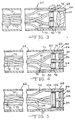
- Fig. 3 is a cross-sectional view with parts broken away of the distal end of one embodiment of a stereoscopic endoscope according to the present invention.
- Fig. 4 is a cross-sectional view with parts broken away of the distal end of another embodiment of a stereoscopic endoscope according to the present invention.
- Fig. 5 is a cross-sectional view with parts broken away of the distal end of still another embodiment of a stereoscopic endoscope according to the present invention.
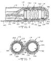
- Fig. 6 is a cross-sectional view of the distal end of a further embodiment of a stereoscopic endoscope having a hinged end cap in a closed position.
- Fig. 7 is an end view of the stereoscopic endoscopic shown in Fig. 6 with the hinged end cap in an opened position.
- Figs. 1 and 2 show a battery powered, sterilizable video endoscope 10 according to one embodiment of the present invention.
- the endoscope 10 comprises a conduit housing 12 having a tubular shape.
- the tubular housing 12 is preferably made of metal and it can be rigid, as shown, or the housing can be flexible and constructed by pivotally connecting the mutually facing ends of a plurality of juxtaposed rings, as is well known to those skilled in the art.
- a proximal end 14 of the housing 12 is joined to a T-shaped connector 16 having a light guide post 18 through which optical glass fibers 20 are disposed.
- An adaptor 22 is joined to the connector 16 opposite the tubular housing 12.
- the adaptor 22 serves to detachably mount a battery 24 for supplying electrical power to the various electronic components of the endoscope 10, as will be explained in detail hereinafter.
- Adaptor 22 is an extensidn of the proximal end 14 of housing 12.
- Objective optics comprising a lens system 26 are housed in a cylindrically shaped optics fitting 28 disposed inside the distal end 30 of the tubular housing 12.
- the optical glass fibers 20 begin in the T-shaped connector 16 at the guide post 18 and extend the length of the tubular housing 12 to the distal end 30 thereof. There, they are positioned in a tightly packed manner circumferentially around the optics fitting 28 to confine the optics fitting 28 centered inside the tubular housing 12.
- a fiber optic light cable 32 attaches to guide post 18 and supplies light from a remote white light source 34 to the optical glass fibers 20 which in turn transmits the light to the distal end 30 of the tubular housing 12 from which the light is directed onto the site under investigation.
- a visual image is then reflected from the investigation site through the lens system 26 and to an associated charge coupled device 36, also known as a CCD, for sensing the image.
- the CCD 36 converts the visual image into electrical signals that are transmitted through electrical leads 38 via an electronic package 40 to a pair of radio frequency transceiver components 42 located in the adaptor 22.
- the light source 34 is a relatively compact component that is positionable closely adjacent to the investigation site. In that manner, the light cable 32 does not act as a hinderance to movement of the physician about the operating theater.
- the electrical power is supplied from the battery 24 to the endoscope 10 including the transceivers 42 through electronic interface circuits on boards 44, some of which are mounted on an end wall 46 of the adaptor 22.
- the electrical signals containing information on images of the investigation site are transmitted by the transceivers 42 as electromagnetic radio waves to a remote video processor 48.
- the radio waves are converted to a video image viewable on a TV monitor 50 connected to the processor 48.
- the monitor 50 may include a VCR for recording the video image.
- the video processor 48 also transmits electromagnetic radio waves back to the transceivers 42 as telemetry control signals for controlling the operation thereof in a known manner.
- the battery 24 is preferably detachable from the endoscope 10 for replacement at such time as its energy capacity has been depleted to an extent where it is no longer safe for use during the investigation or operative procedure.
- the battery 24 is sterilizable in a steam autoclave (not shown) along with the endoscope 10. For that reason, both the endoscope 10 and battery 24 are constructed to remain hermetically sealed over a broad range from about -70 cm Hg to about 2 to 3 atmospheres, and at autoclave temperatures as high as about 135°C.
- a suitable autoclavable battery is manufactured by Wilson Greatbatch Ltd., Clarence, New York under Model No. HTS C/D.
- optical fibers 20 are of the type commercially available from Fiber Optic Technologies located in Connectic.ut under the designation White Light Fiber
- lens system 26 and optics fitting 28 are custom configured and commercially available from P.O.C. located in Massachusetts
- charge coupled device 36 is commercially available from Panasonic under the designation KS 152
- the transceivers 40 are commercially available from Motorola.
- the circuit components on boards 44 are either selected to withstand the autoclave sterilizations or are encapsulated within a potting compound which can withstand such temperatures.
- a first embodiment of a battery powered, sterilizable stereoscopic endoscope 60 having a tubular conduit housing 62 preferably made of metal.
- the housing 62 for the stereoscopic endoscope 60 can be rigid, as shown, or the housing can be flexible.
- Objective optics comprising a lens system 64 are housed in a cylindrically shaped optics fitting 66 disposed inside the distal end 68 of the tubular housing 62.
- Optical glass fibers 70 are positioned in a tightly packed manner circumferentially around the optics fitting 66 to confine the optics fitting centered inside the tubular housing. While not shown in Fig.
- the proximal end of the optical glass fibers 70 extend the length of the tubular housing 62 to a guide post attachable to a fiber optic light cable that supplies light from the remote white light source 34 (Fig. 1), in a similar manner as previously described with respect to the endoscope 10.
- the light is directed from the optical glass fibers 70 onto the site under investigation and a visual image is then reflected from the investigation site through the lens system 64 and to a pair of side-by-side CCDs 72, 74.
- the CCDs 72, 74 are separated and retained in place by a metal spacer 76 disposed therebetween.
- the CCDs convert the visual image into electrical signals that are transmitted through electrical leads 78 via respective electronic packages 80, 82 to the previously described radio frequency transceiver components 42 (Fig. 2).
- the pair of CCDs 72, 74 serve to divide the reflected image, and the electronic packages 80, 82 and transceivers in turn transmit electromagnetic radio waves to the remote video processor 48 related to the two portions of the divided reflected image.
- the video processor 48 also transmits electromagnetic radio waves back to the transceivers as telemetry control signals for controlling-the operation thereof in a known manner. That way, the stereoscopic endoscope 60 provides the physician with a clear and well defined three-dimensional view of the investigation site on the TV monitor 50.
- a battery such as battery 24 (Figs. 1 and 2)
- the battery for the stereoscopic endoscope 60 is preferably detachable therefrom for replacement and so that it can be sterilized separate from the endoscope 60.
- the components comprising the stereoscopic endoscope 60 are selected to be sterilizable, preferably by steam or heat sterilization.
- Fig. 4 shows the distal end of another embodiment of a battery powered, sterilizable stereoscopic endoscope 90 according to the present invention.
- This stereoscopic endoscope differs from the stereoscopic endoscope 60 shown in Fig. 3 in that the visual image reflected from the investigation site is returned to objective optics comprising a pair of side-by-side lens systems 92, 94.
- the reflected light passes through the side-by-side lens systems 92, 94 to the pair of dedicated side-by-side CCDs 72, 74 that convert the respective received visual images into electrical signals that are transmitted through electrical leads 78 via the associated electronic packages 80, 82 to radio frequency transceivers 42 (Fig. 2).
- the lens systems 92, 94 serve to divide the reflected image into two portions which the CCDs 72, 72 and the electronic packages 80, 82 in conjunction with the transceivers transmit as electromagnetic radio waves to the remote video processor 48 to provide the physician with a three-dimensional view of the investigation site on the TV monitor 50.
- the video processor 48 also transmits electromagnetic radio waves to the transceivers for telemetry control.
- the lens systems 92, 94, the CCDs 72, 74 and the associated electronic packages 80, 82 are separated and retained in place by a metal spacer 96 disposed therebetween.
- a detachable battery (not shown) is provided for powering the stereoscopic endoscope 90.
- the battery and the various components comprising the endoscope 90 are selected to be sterilizable such as in a steam autoclave.
- Fig. 5 shows the distal end of still another embodiment of a battery powered, sterilizable stereoscopic endoscope 100 according to the present invention.
- the visual image reflected from the investigation site is returned and reflected through objective optics comprising the pair of side-by-side lens systems 92, 94 and a single dedicated CCD 102.
- the lens systems 92, 94 are separated and retained in place by a metal spacer 104 disposed therebetween.
- the CCD 102 is configured to convert the visual image from the lens system pair 92, 94 into electrical signals that are transmitted as discrete data packets related to that portion of the reflected image captured by each lens system 92, 94 through electrical leads 104 via an electronics package 106 to the radio frequency transceiver components 42 (Fig. 2).
- the transceivers 42 then transmit electromagnetic radio waves of the visual images from the lens systems 92, 94 to the remote video processor 48 to permit the physician to view a three-dimensional representation of the investigation site on the TV monitor 50.
- Control telemetry is also transmitted from the processor 48 to the transceivers 42.
- a detachable and autoclavable sterilizable battery (not shown) is provided to power the stereoscopic endoscope 100 whose components are selected to be heat or steam sterilizable.
- Figs. 6 and 7 show a further embodiment of the distal end of a battery powered, sterilizable stereoscopic endoscope 110 according to the present invention.
- Stereoscopic endoscopic 110 includes a tubular conduit housing 112, preferably made of metal, having an end cap 114 pivotally attached by a hinge 116 to the distal end thereof.
- the hinge 116 is normally biased into an opened position by means of a coil spring (not shown) extending around hinge 116.
- a first objective optics comprising a lens system 118 is positioned inside a cylindrically shaped optics fitting 120 disposed inside the distal end of the tubular housing.
- Optical glass fibers 122 are positioned circumferentially around the optics fitting 120 to help confine the optics fitting coaxially positioned inside the tubular housing 112.
- a first CCD 124 is mounted inside the fitting 120 just behind the lens system 118 to receive the light passing through the lens system 118 and to convert this light into electrical signals that are transmitted through electrical leads 126 via an electronic package 128 to the previously described radio frequency transceivers 42 (Fig. 2).
- a second objective optics comprising a second lens system 130 is positioned inside a cylindrically shaped optics fitting 132 disposed inside the end cap 114.
- the second lens system 130 has an associated CCD 134 positioned inside the fitting 132 to receive the light passing therethrough and to convert it into electrical signals.
- the electrical signals from the second CCD 134 are transmitted via a second electronic package 136 by electrical leads 138 which extend through the end cap 114, past hinge 116 and along the length of the tubular housing 112 to the radio frequency transceivers 42.
- the transceivers 42 then transmit electromagnetic radio waves to the remote video processor 48 corresponding to the electrical signals from both the first lens system 118 located in the distal end of tubular housing 112 and the second lens system 130 located in the end cap 114 hinged to the housing 112. Control telemetry is also transmitted from the processor 48 to the transceivers for both CCDs 124, 134 associated with the first and second lens systems 118, 130.
- the first and second lens systems 118, 130 are in a face-to-face relationship when the end cap 114 is in a closed position on the distal end of the tubular housing 112.
- a locking rod 140 is mounted for sliding movement through a channel 142 extending within and along the length of the tubular housing 112.
- the locking rod 140 has a distal end that extends into a sleeve 144 in end cap 114 with a friction fit sufficient to retain end cap 114 in the closed position against the force of the coil spring extending around the hinge 116.
- optical glass fibers 122 are positioned in a tightly packed configuration around the first optics fitting 120 for the purpose of retaining the fitting in place and for illuminating the investigation site at such time as the end cap 114 is in the opened position (Fig. 7). Additional optical glass fibers 146 extend beyond the first optics fitting 120 adjacent to the hinge 116 to the dome portion 148 of end cap 114 where they double back and fan out in a tightly packed manner along and around the second optics fitting 132 to the open end of end cap to further illuminate the investigation site with the end cap 114 in the opened position.
- Suitable potting material 150 is provided proximate the optical glass fibers 122, 146 adjacent to the first and second optics fittings 120, 132 to prevent circumferential movement of the optical fibers 122, 146 and the electrical leads 138 for the second electronic package 136 while providing for a sufficient amount of play in the optical fibers 146 and the leads 138 as the end cap 114 is moved between the opened and the closed positions.
- Electrical power for the stereoscopic endoscope 110 is supplied from a battery, such as battery 24 (Figs. 1 and 2).
- a battery such as battery 24 (Figs. 1 and 2).
- the battery is preferably detachable therefrom and both the battery and the endoscope are selected to be sterilizable such as in a steam autoclave.
- the stereoscopic endoscope 110 is inserted to the operative site and the locking rod 140 is withdrawn from the sleeve 144 so that the end cap 114 pivots about hinge 116 to the opened position shown in Fig. 7.
- This arrangement creates a parallax wherein lens system 118 and associated CCD 124 and electronic package 128 lie along a first axis parallel to the longitudinal axis of the tubular housing 112 and the second lens system 130 and associated CCD 134 and electronic package 136 lie along a second axis parallel to the first axis.
- the resulting image seen by the physician on the TV monitor 50 is a wide-angle three dimensional view of the investigation site.
- the end cap 114 When it is desired to withdraw the stereoscopic endoscope 110 from the operation site, the end cap 114 is pushed to the closed position by engagement with the end of a trocar (not shown) through which the endoscope has been introduced into the body. Alternatively, the end cap 114 is pushed to the closed position by engagement with a body passageway through which the endoscope has been introduced to the operation site.
- the present invention provides all the advantages of an endoscope that is heat sterilizable so that the endoscope is reusable without serving as a source of infection and as a carrier of disease from a one patient to the next. Additionally, radio transmission of the electrical image signals of the investigation site eliminates the need for a transmission cable connected between the CCD electronics and the remote video processor. This is a significant improvement in helping free the physician for unteathered movement about the operating theater when using the present endoscope.
Landscapes
- Health & Medical Sciences (AREA)
- Life Sciences & Earth Sciences (AREA)
- Surgery (AREA)
- Engineering & Computer Science (AREA)
- General Health & Medical Sciences (AREA)
- Molecular Biology (AREA)
- Pathology (AREA)
- Veterinary Medicine (AREA)
- Public Health (AREA)
- Biophysics (AREA)
- Biomedical Technology (AREA)
- Heart & Thoracic Surgery (AREA)
- Medical Informatics (AREA)
- Physics & Mathematics (AREA)
- Animal Behavior & Ethology (AREA)
- Optics & Photonics (AREA)
- Nuclear Medicine, Radiotherapy & Molecular Imaging (AREA)
- Radiology & Medical Imaging (AREA)
- Computer Networks & Wireless Communication (AREA)
- Instruments For Viewing The Inside Of Hollow Bodies (AREA)
- Endoscopes (AREA)
Applications Claiming Priority (2)
| Application Number | Priority Date | Filing Date | Title |
|---|---|---|---|
| US560903 | 1983-12-14 | ||
| US56090395A | 1995-11-20 | 1995-11-20 |
Publications (1)
| Publication Number | Publication Date |
|---|---|
| EP0774231A1 true EP0774231A1 (de) | 1997-05-21 |
Family
ID=24239835
Family Applications (1)
| Application Number | Title | Priority Date | Filing Date |
|---|---|---|---|
| EP96307070A Withdrawn EP0774231A1 (de) | 1995-11-20 | 1996-09-27 | Batteriegespeistes elektronisches Videoendoskop |
Country Status (2)
| Country | Link |
|---|---|
| EP (1) | EP0774231A1 (de) |
| JP (1) | JPH09266879A (de) |
Cited By (10)
| Publication number | Priority date | Publication date | Assignee | Title |
|---|---|---|---|---|
| DE10056438A1 (de) * | 2000-11-14 | 2002-05-23 | Forschungszentrum Fuer Medizin | Endoskopisches Gerätesystem |
| US6712760B2 (en) | 2000-04-10 | 2004-03-30 | Pentax Corporation | Television device of portable endoscope |
| WO2004030526A1 (en) * | 2002-09-30 | 2004-04-15 | Power Medical Interventions, Inc. | Self-contained sterilizable surgical system |
| WO2006073186A1 (ja) | 2005-01-07 | 2006-07-13 | Olympus Medical Systems Corp. | 内視鏡用挿入部 |
| DE10108406B4 (de) * | 2000-02-21 | 2007-01-18 | Pentax Corp. | Endoskopsystem und Videokamera hierfür |
| US7751870B2 (en) | 2002-01-30 | 2010-07-06 | Power Medical Interventions, Llc | Surgical imaging device |
| WO2011128610A1 (en) * | 2010-04-15 | 2011-10-20 | Smiths Medical International Limited | Video apparatus |
| EP2412290A1 (de) * | 2010-07-30 | 2012-02-01 | Stephan Flegler | Endoskop und Endoskopsystem |
| US8262560B2 (en) | 2001-04-20 | 2012-09-11 | Tyco Healthcare Group Lp | Imaging device for use with a surgical device |
| EP3613331A1 (de) * | 2018-08-24 | 2020-02-26 | Karl Storz SE & Co. KG | Endoskop mit einem bewegbaren bauteil |
Families Citing this family (3)
| Publication number | Priority date | Publication date | Assignee | Title |
|---|---|---|---|---|
| JP4772286B2 (ja) * | 2004-02-23 | 2011-09-14 | オリンパス株式会社 | バッテリ装置 |
| WO2011062287A1 (ja) * | 2009-11-20 | 2011-05-26 | 国立大学法人東北大学 | 挿入器具および内視鏡 |
| JP6223056B2 (ja) * | 2013-08-13 | 2017-11-01 | オリンパス株式会社 | 3次元画像システム |
Citations (7)
| Publication number | Priority date | Publication date | Assignee | Title |
|---|---|---|---|---|
| EP0018125A1 (de) * | 1979-04-02 | 1980-10-29 | Olympus Optical Co., Ltd. | Kamera für die Verwendung mit einem Endoskop |
| JPH04109927A (ja) * | 1990-08-31 | 1992-04-10 | Toshiba Corp | 電子内視鏡装置 |
| US5188094A (en) * | 1991-09-30 | 1993-02-23 | Adair Edwin Lloyd | Heat sterilizable electronic video endoscope |
| US5381784A (en) * | 1992-09-30 | 1995-01-17 | Adair; Edwin L. | Stereoscopic endoscope |
| EP0677272A1 (de) * | 1994-03-24 | 1995-10-18 | Sightline Technologies Ltd | Gerät zur Abbildung des Inneren des Dickdarms |
| JPH07327922A (ja) * | 1994-06-03 | 1995-12-19 | Asahi Optical Co Ltd | 電子内視鏡装置 |
| JPH08150114A (ja) * | 1994-11-29 | 1996-06-11 | Fukuda Denshi Co Ltd | 内視鏡システム |
-
1996
- 1996-09-27 EP EP96307070A patent/EP0774231A1/de not_active Withdrawn
- 1996-10-29 JP JP8324521A patent/JPH09266879A/ja active Pending
Patent Citations (7)
| Publication number | Priority date | Publication date | Assignee | Title |
|---|---|---|---|---|
| EP0018125A1 (de) * | 1979-04-02 | 1980-10-29 | Olympus Optical Co., Ltd. | Kamera für die Verwendung mit einem Endoskop |
| JPH04109927A (ja) * | 1990-08-31 | 1992-04-10 | Toshiba Corp | 電子内視鏡装置 |
| US5188094A (en) * | 1991-09-30 | 1993-02-23 | Adair Edwin Lloyd | Heat sterilizable electronic video endoscope |
| US5381784A (en) * | 1992-09-30 | 1995-01-17 | Adair; Edwin L. | Stereoscopic endoscope |
| EP0677272A1 (de) * | 1994-03-24 | 1995-10-18 | Sightline Technologies Ltd | Gerät zur Abbildung des Inneren des Dickdarms |
| JPH07327922A (ja) * | 1994-06-03 | 1995-12-19 | Asahi Optical Co Ltd | 電子内視鏡装置 |
| JPH08150114A (ja) * | 1994-11-29 | 1996-06-11 | Fukuda Denshi Co Ltd | 内視鏡システム |
Non-Patent Citations (3)
| Title |
|---|
| PATENT ABSTRACTS OF JAPAN vol. 016, no. 356 (C - 0969) 31 July 1992 (1992-07-31) * |
| PATENT ABSTRACTS OF JAPAN vol. 96, no. 10 31 October 1996 (1996-10-31) * |
| PATENT ABSTRACTS OF JAPAN vol. 96, no. 4 30 April 1996 (1996-04-30) * |
Cited By (17)
| Publication number | Priority date | Publication date | Assignee | Title |
|---|---|---|---|---|
| DE10108406B4 (de) * | 2000-02-21 | 2007-01-18 | Pentax Corp. | Endoskopsystem und Videokamera hierfür |
| US6712760B2 (en) | 2000-04-10 | 2004-03-30 | Pentax Corporation | Television device of portable endoscope |
| DE10056438A1 (de) * | 2000-11-14 | 2002-05-23 | Forschungszentrum Fuer Medizin | Endoskopisches Gerätesystem |
| US8262560B2 (en) | 2001-04-20 | 2012-09-11 | Tyco Healthcare Group Lp | Imaging device for use with a surgical device |
| US7751870B2 (en) | 2002-01-30 | 2010-07-06 | Power Medical Interventions, Llc | Surgical imaging device |
| US9867523B2 (en) | 2002-01-30 | 2018-01-16 | Covidien Lp | Surgical imaging device |
| US8812086B2 (en) | 2002-01-30 | 2014-08-19 | Covidien Lp | Surgical imaging device |
| CN101904734B (zh) * | 2002-09-30 | 2013-01-02 | Tyco医疗健康集团 | 整装的可灭菌外科系统 |
| EP2186465A1 (de) * | 2002-09-30 | 2010-05-19 | Power Medical Interventions, LLC | Unabhängiges sterilisierbares chirurgisches System |
| US8696552B2 (en) | 2002-09-30 | 2014-04-15 | Covidien Lp | Self-contained sterilizable surgical system |
| WO2004030526A1 (en) * | 2002-09-30 | 2004-04-15 | Power Medical Interventions, Inc. | Self-contained sterilizable surgical system |
| US8033990B2 (en) | 2005-01-07 | 2011-10-11 | Olympus Medical Systems Corp. | Endoscope insertion portion |
| EP1834575A4 (de) * | 2005-01-07 | 2009-05-27 | Olympus Medical Systems Corp | Einsatzeinheit zur verwendung mit einem endoskop |
| WO2006073186A1 (ja) | 2005-01-07 | 2006-07-13 | Olympus Medical Systems Corp. | 内視鏡用挿入部 |
| WO2011128610A1 (en) * | 2010-04-15 | 2011-10-20 | Smiths Medical International Limited | Video apparatus |
| EP2412290A1 (de) * | 2010-07-30 | 2012-02-01 | Stephan Flegler | Endoskop und Endoskopsystem |
| EP3613331A1 (de) * | 2018-08-24 | 2020-02-26 | Karl Storz SE & Co. KG | Endoskop mit einem bewegbaren bauteil |
Also Published As
| Publication number | Publication date |
|---|---|
| JPH09266879A (ja) | 1997-10-14 |
Similar Documents
| Publication | Publication Date | Title |
|---|---|---|
| US12226075B2 (en) | Endoscope with variable profile tip | |
| US5817005A (en) | Apparatus and method for simultaneously retracting and viewing bodily tissues | |
| US5630782A (en) | Sterilizable endoscope with separable auxiliary assembly | |
| KR101541988B1 (ko) | 복강경 시스템 | |
| EP0316244B1 (de) | Endoskop in Kanülenform mit Video-Einrichtung | |
| US4651201A (en) | Stereoscopic endoscope arrangement | |
| EP1423042B1 (de) | Endoskopisches system mit festkörperlichtquelle | |
| US5402768A (en) | Endoscope with reusable core and disposable sheath with passageways | |
| TW201031383A (en) | Disposable sheath for use with an imaging system | |
| US20140221740A1 (en) | Wireless endoscopic surgical device | |
| CA2206862A1 (en) | A fog-free endoscope | |
| AU2012202301B2 (en) | Twin camera endoscope | |
| WO1994009694A1 (en) | Electronic endoscope | |
| JPH09266879A (ja) | 内視鏡 | |
| CN112788976B (zh) | 用于执行医疗程序的摄像机和器械定位系统、方法和设备 | |
| WO2012101549A1 (en) | Endoscope with wireless lens module add-on | |
| JPH03275030A (ja) | 内視鏡装置 |
Legal Events
| Date | Code | Title | Description |
|---|---|---|---|
| PUAI | Public reference made under article 153(3) epc to a published international application that has entered the european phase |
Free format text: ORIGINAL CODE: 0009012 |
|
| AK | Designated contracting states |
Kind code of ref document: A1 Designated state(s): DE FR GB |
|
| STAA | Information on the status of an ep patent application or granted ep patent |
Free format text: STATUS: THE APPLICATION IS DEEMED TO BE WITHDRAWN |
|
| 18D | Application deemed to be withdrawn |
Effective date: 19971122 |