EP0774356A2 - Tintenstrahldruckkopf, Tintenstrahldruckvorrichtung und Verfahren zur Wartung eines Tintenstrahldruckkopfes - Google Patents
Tintenstrahldruckkopf, Tintenstrahldruckvorrichtung und Verfahren zur Wartung eines Tintenstrahldruckkopfes Download PDFInfo
- Publication number
- EP0774356A2 EP0774356A2 EP96118185A EP96118185A EP0774356A2 EP 0774356 A2 EP0774356 A2 EP 0774356A2 EP 96118185 A EP96118185 A EP 96118185A EP 96118185 A EP96118185 A EP 96118185A EP 0774356 A2 EP0774356 A2 EP 0774356A2
- Authority
- EP
- European Patent Office
- Prior art keywords
- ink
- ink jet
- print head
- jet print
- gas hold
- Prior art date
- Legal status (The legal status is an assumption and is not a legal conclusion. Google has not performed a legal analysis and makes no representation as to the accuracy of the status listed.)
- Granted
Links
Images




Classifications
-
- B—PERFORMING OPERATIONS; TRANSPORTING
- B41—PRINTING; LINING MACHINES; TYPEWRITERS; STAMPS
- B41J—TYPEWRITERS; SELECTIVE PRINTING MECHANISMS, i.e. MECHANISMS PRINTING OTHERWISE THAN FROM A FORME; CORRECTION OF TYPOGRAPHICAL ERRORS
- B41J2/00—Typewriters or selective printing mechanisms characterised by the printing or marking process for which they are designed
- B41J2/005—Typewriters or selective printing mechanisms characterised by the printing or marking process for which they are designed characterised by bringing liquid or particles selectively into contact with a printing material
- B41J2/01—Ink jet
- B41J2/17—Ink jet characterised by ink handling
- B41J2/1707—Conditioning of the inside of ink supply circuits, e.g. flushing during start-up or shut-down
-
- B—PERFORMING OPERATIONS; TRANSPORTING
- B41—PRINTING; LINING MACHINES; TYPEWRITERS; STAMPS
- B41J—TYPEWRITERS; SELECTIVE PRINTING MECHANISMS, i.e. MECHANISMS PRINTING OTHERWISE THAN FROM A FORME; CORRECTION OF TYPOGRAPHICAL ERRORS
- B41J2/00—Typewriters or selective printing mechanisms characterised by the printing or marking process for which they are designed
- B41J2/005—Typewriters or selective printing mechanisms characterised by the printing or marking process for which they are designed characterised by bringing liquid or particles selectively into contact with a printing material
- B41J2/01—Ink jet
- B41J2/135—Nozzles
- B41J2/14—Structure thereof only for on-demand ink jet heads
- B41J2/14016—Structure of bubble jet print heads
- B41J2/14145—Structure of the manifold
-
- B—PERFORMING OPERATIONS; TRANSPORTING
- B41—PRINTING; LINING MACHINES; TYPEWRITERS; STAMPS
- B41J—TYPEWRITERS; SELECTIVE PRINTING MECHANISMS, i.e. MECHANISMS PRINTING OTHERWISE THAN FROM A FORME; CORRECTION OF TYPOGRAPHICAL ERRORS
- B41J2/00—Typewriters or selective printing mechanisms characterised by the printing or marking process for which they are designed
- B41J2/005—Typewriters or selective printing mechanisms characterised by the printing or marking process for which they are designed characterised by bringing liquid or particles selectively into contact with a printing material
- B41J2/01—Ink jet
- B41J2/135—Nozzles
- B41J2/14—Structure thereof only for on-demand ink jet heads
- B41J2002/14379—Edge shooter
Definitions
- the present invention relates to an ink jet print head which jets out ink from an ink jet port to thereby form an image on a recording medium, an on-demand type of ink jet printer including such ink jet print head, and a maintenance method for maintaining such ink jet print head.
- an ink jet printer using an ink jet print head of a piezoelectric type that a pressure chamber is mechanically deformed by means of piezoelectric material and the resultant pressure is used to jet out ink from its ink jet port
- an ink jet printer using a thermal ink jet print head structured such that a heater disposed in an ink flow passage is electrically energized to vaporize ink and the pressure of the vaporized ink is used to jet out ink from its ink jet port.
- the ink jet printers has been developed to increase the number of nozzles which are used to jet out ink in order to improve the quality of a printed image and increase the printing speed thereof.
- the number of nozzles is increased, then there is increased the pressure that is transmitted from a pressure generation source to a common ink chamber with which a plurality of nozzles are in communication in common.
- Such increased pressure causes an unstable ink jetting condition, or impedes the ink supply to thereby make it impossible to jet out ink.
- Fig. 19 is a graphical representation which shows an example of pressure variations in a common ink chamber used in a conventional ink jet printer. For example, if printing a pattern having a high coverage is started, then pressure for jetting out ink is generated in all of the nozzles. The pressures generated in the respective nozzles are all transmitted to the common ink chamber and, therefore, as a whole, a large pressure is temporarily applied from the nozzles to the common ink chamber. After then, in order to carry out next printing, ink is supplied from the common ink chamber to the nozzles. In such ink supply, due to the flow of the ink, pressure is applied from the common ink chamber to the nozzles.
- Figs. 20A and 20B are explanatory views of a printed state of the conventional ink jet printer obtained when the image quality thereof is poor. If printing is carried out in such an unstable jetting condition as mentioned above, for example, when a large pressure is applied in a direction to go from the common ink chamber to the nozzles, as shown in Fig. 20A, not only dots are printed by normal ink droplets, but also there occurs a phenomenon that small ink droplets are jetted at a timing different from the normal print timing to thereby increase the density of the printed dots partially.
- Unexamined Japanese Patent Publication (kokai) No. Hei. 1-308644 discloses that a pressure-volume converter is provided within an ink chamber. In this structure, since no air is used, there can be obtained a stable pressure relieving function. However, use of a new part, that is, the pressure-volume converter, increases not only the number of steps to produce it but also the cost thereof.
- an ink jet print head for jetting out ink from a plurality of nozzles to thereby form an image, is comprised of: a plurality of energy generator for causing the ink to be jetted out from the nozzles; a plurality of ink flow passages respectively which is disposed to individually correspond to the energy generator for supplying ink to the energy generator; an ink jet head including an ink reservoir with which the plurality of ink flow passages communicate in common; and an ink supply member including an ink supply passage for supplying ink to the ink reservoir of the ink jet head, the ink supply member further including a plurality of gas hold portions which are respectively in communication with only the ink reservoir and are respectively capable of holding gas therein.
- the present invention due to the compression/expansion of gas to be held within a plurality of gas hold portions, pressure transmission within an ink tank and a common reservoir due to the flow of ink in printing can be controlled, so that ink can be always jetted out stably, and thus high image quality can be realized without producing unprinted area or density variations. Also, since the gas hold portions are respectively in communication with the portions of the common reservoir where ink flows only a little, there is eliminated the possibility that the gas within the gas hold portions can be made to flow out therefrom due to the flow of the ink, which can always realize a stable pressure adjust function. Further, because the gas hold portions are formed in the ink supply member, no new parts are necessary and the ink jet print head can be manufactured with no special process, while the size of the print head remains unchanged.
- FIG. 1 is a perspective view
- Fig. 2 is a section view taken along the line A-A'
- Fig. 3 is a section view taken along the line B-B'
- Fig. 4 is a section view taken along the line D-D'
- Fig. 5 is a section view taken along the line C-C'.
- reference numeral 1 designates a heater substrate; 2, a channel substrate; 3, a nozzle; 4, a heating element; 5, an ink flow passage; 6, a common reservoir; 7, recessed portions; 11, an ink supply member; 12, an ink supply passage; and 13, a gas hold portion.
- the channel substrate 2 includes a plurality of ink flow passages 5 which are respectively so formed as to correspond to a plurality of nozzles 3, and further includes the common reservoir 6 which is so provided as to communicate in common with the ink flow passages 5.
- the common reservoir 6 is formed to extend through the channel plate 2.
- a single common reservoir 6 is formed to communicate in common with all of the ink flow passages 5.
- this is not limitative but, instead of a single common reservoir 6, a plurality of common reservoirs may also be formed.
- a plurality of heating elements 4 are provided to respectively correspond to the ink flow passages 5, and as shown in Figs. 2 and 3, a plurality of recessed portions 7 are formed to respectively extend from the upper portions of the heating elements 4 to communicate the ink flow passages 5 with common reservoir 6.
- Each of the recessed portions 7, as shown in Fig. 5, is formed narrow in part and the wall surface of the recessed portion 7 on the common reservoir 6 side thereof is formed in an arc shape. Such shape of the recessed portion 7 makes it difficult to transmit the pressure generated on the heating element 4 to the common reservoir 6.
- the heater substrate 1 and channel substrate 2 are bonded to each other, a flow passage for ink extending from the common reservoir 6 through the recessed portions 7 to the ink flow passages 5 is formed.
- the heater substrate 1 and channel substrate 2 are respectively provided in large number on a wafer and are bonded to each other and, thereafter, they are separated by dicing or the like. While they are bonded, the end portions of the ink flow passages 5 and the through opening of the common reservoir 6 are exposed. In this state, the end portions of the ink flow passages 5 respectively provide the nozzles 3.
- the ink supply member 11 is mounted on the through opening of the common reservoir 6.
- an ink supply passage 12 and a plurality of gas hold portion 13 are formed.
- the ink supply passage 12 is used to supply ink from an ink tank (not shown) to the common reservoir 6, and a plurality of gas hold portions 13 are respectively capable of holding gas therein.
- Each of the gas hold portions 13, as shown in Fig. 3, is formed in a substantially circular hole which is in communication with only the common reservoir 6 but does not extend through the ink supply member 11. After ink is charged, variations in the pressure within the common reservoir 6 can be relieved by the gas retained within the gas hold portions 13. Actually, as shown in Fig. 4, such gas hold portions 13 are arranged at almost equal intervals together with the ink supply passage 12. Since the gas hold portions 13 can be formed together with the ink supply passage 12 when the ink supply member 11 is molded, there is no possibility that formation of the gas hold portions 13 can complicate the manufacturing process of the ink jet print head.
- Ink is guided from an ink tank (not shown) through the ink supply passages 12 in the ink supply member 11 to the common reservoir 6.
- the ink that is guided to the common reservoir 6 is charged into the common reservoir 6 as well as the respective ink flow passages 5 are filled with the thus charged ink.
- the ink is pulled simultaneously by not only a negative pressure generated within the ink tank but also a surface tension which is generated in the interfaces of the ink in the respective ink flow passages 5, there is no possibility that the ink can leak while printing is not in operation. Also, when the ink is fully loaded into the common reservoir 6, gas is retained within the respective gas hold portions 13.
- a maintenance operation is carried out to stabilize the respective parts of the ink jet print head.
- the maintenance operation is carried out after the initial loading of the ink, or after ink is replaced, or after an ink suction maintenance operation is executed when trouble occurs.
- a concrete maintenance operation for example, after the ink jet print head is heated to, for example, about 60°C, ink is sucked from the nozzle 3 side.
- gas held within the gas hold portions 13 is expanded as the temperature rises. Then, since the amount of the gas that is expanded due to the temperature rising is discharged into the common reservoir 6, the thus discharged gas is then discharged externally by means of suction of the ink.
- the heating elements 4 which are respectively disposed in the ink flow passages 5 corresponding to the respective nozzles 3 from which ink is jetted out are electrically energized so as to be heated.
- the ink is jetted out from the nozzles 3 and is flown onto a recording medium to execute recording.
- the pressure of the air bubbles is also transmitted to the rear portion of the recessed portion 7 and is further transmitted to the common reservoir 6.
- the pressure is a force which goes in a direction from the ink flow passages 5 to the common reservoir 6.
- the air bubbles are extinguished as well as the ink is in short supply on the heating elements 4. Therefore, a force in a direction from the common reservoir 6 to the ink flow passages 5 is applied, so that ink is supplied from the common reservoir 6 to the ink flow passages 5.
- the ink flows in a direction from the ink supply passages 12 to the recessed portions 7 corresponding to the respective ink flow passages 5. Therefore, a position where the gas hold portion 13 communicates with the common reservoir 6 is a portion where ink flow a little. This makes it possible to restrict the outflow of the gas within the gas hold-portions 13 due to the flow of the ink which occurs in the conventional print head. Accordingly, the pressure variations within the common reservoir 6 can be controlled stably.
- Fig. 6 is a graphical representation to show an example of the pressure variations produced in the common reservoir employed in the above embodiment of an ink jet print head according to the present invention.
- the pressure variations within the common reservoir 6 can be restricted by the gas hold portions 13, even when printing is executed under the same condition as the case shown in Fig. 13, as shown in Fig. 6, there cannot be found large pressure variations and thus the printing can also be executed normally.
- Figs. 7 and 8 there is shown a first modification of the above embodiment of the ink jet print head according to the invention.
- Fig. 7 is a section view taken along the line B-B' shown in Fig. 1
- Fig. 8 is a section view taken along the line D-D' shown in Fig. 1.
- the section area of the gas hold portion 13 is increased. If the section area of the gas hold portion 13 is increased in this manner, then the volume of the gas hold portion 13 can be increased and thus the amount of gas to be held within the gas hold portion 13 can be increased. This makes it possible to increase the function to restrict the variations in the pressure within the common reservoir 6. Also, when a sufficient length cannot be secured in the gas hold portion 13, if the section area of the gas hold portion 13 is increased in this manner, then the amount of the gas to be held within the gas hold portion 13 can be secured.
- Figs. 9 and 10 show a second modification of the above embodiment of the ink jet print head according to the invention.
- Fig. 9 is a section view taken along the line B-B' shown in Fig. 1
- Fig. 10 is a section view taken along the line D-D' shown in Fig. 1.
- the position of each of the gas hold portions 13 is displaced.
- the section areas of the communication portions between the respective gas hold portions 13 and the common reservoir 6 are reduced, it is possible to further restrict the inflow of the ink to the gas hold portions 13 as well as the outflow of the gas therefrom, which in turn makes it possible to restrict the pressure variations within the common reservoir 6 more stably.
- each gas hold portion 13 since the position of each gas hold portion 13 is displaced on the opposite side to its corresponding nozzle 3, for example, even in a ink jet printer of a type that the nozzle 3 faces downward and ink droplets are flown downward, the gas within the gas hold portion 13 is prevented from flowing out therefrom and the pressure variations within the common reservoir 6 can be restricted properly.
- Figs. 11 and 12 show a third modification of the above embodiment of the ink jet print head of the invention.
- Fig. 11 is a section view taken along the line B-B' shown in Fig. 1
- Fig. 12 is a section view taken along the line D-D' shown in Fig. 1.
- each of the gas hold portions 13 is formed to extend obliquely backward.
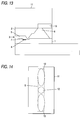
- Fig. 13 is a section view taken along the line B-B' shown in Fig. 1, and shows a fourth modification of the above embodiment of the ink jet print head of the invention.
- the present modification in the surface of the ink supply member 11, a groove which serves as the gas hold portion 13 is formed and the ink supply member 11 is bonded to the channel substrate 2.
- one surface of the gas hold portion 13 provides the surface of the channel substrate 2.
- the present modification is effective especially when the ink droplets are jetted out downward.
- the channel substrate 2 since the surface of the channel substrate 2 is used as part of the gas hold portion 13, the channel substrate 2 requires a length which extends backwardly of the common reservoir 6, and also the bonded portion must be airtight.
- the gas hold portion 13 can be formed to be bent in the ink supply member 11.
- Fig. 14 is a section view taken along the line D-D' shown in Fig. 1 and shows a fifth modification of the above embodiment of the ink jet print head of the invention.
- the gas hold portion 13 has a section shape which extends along an opening formed in the common reservoir 6. That is, since the area of the communication portion between the gas hold portion 13 and the common reservoir 6 is increased, the pressure that is transmitted to the interior of the common reservoir 6 can be received in a wide range and can be thereby dampened. Also, since the capacity of the gas hold portion 13 can be increased, the effect to restrict the pressure variations within the common reservoir 6 can be enhanced.
- the gas hold portion 13 can also be formed in other shape, for example, it may be formed in a rectangular shape or in a triangular shape.
- the shape and position of the gas hold portion 13 can be set freely, provided that they extend along the opening of the common reservoir 6. Further, it is also possible to combine together two or more of the above-mentioned embodiment and modifications thereof.
- an ink jet print head including a flow passage structure which communicates the ink flow passages 5 with the common reservoir 6 by means of the recessed portions 7.
- the invention is not limited to this flow passage structure but, for example, it is also possible to employ other various flow passage structures such as a structure including a common slit formed in part thereof or the like, provided that the ink jet print head includes the common reservoir 6.
- ink jet print head if the above-mentioned type of ink jet print head is incorporated into a printer, it is possible to structure an ink jet printer which can prevent unprinted (missing) areas or density variations to thereby be able to obtain printed images of high quality.
- Fig. 15 is an explanatory view of Examples which was conducted in connection with the above embodiment of an ink jet print head according to the invention. Also, Figs. 16 to 18 are explanatory views of the positions and shapes of gas hold portions provided in the examples.
- an ink jet print head was used in which 125 pieces of nozzles were arranged, and the capacity of the ink droplets to be jetted out from each of the nozzles was 80 pl, while the ink jet print head was driven at a print frequency of 7 KHz.
- the through opening of the common reservoir 6 had a width of 0.5 mm and a length of 10.4 mm.
- Fig. 15 there are shown the amounts of gas per ink jet amount which are respectively obtained when the total amounts of gas within a plurality of gas hold portions 13 are divided by the maximum flow amount of ink.
- head numbers in Fig. 15 identify the ink jet print heads that are employed in the Examples.
- An ink jet print head designated by the head No. 0 represents a conventional head in which the gas hold portion 13 is not provided. In this head, as described above, there were produced such density variations or unprinted area as shown in Fig. 20.
- An ink jet print head, head No. 1 is an ink jet print head in which there are formed four gas hold portions 13 each having a diameter of 0.4 mm and a depth of 2 mm.
- the gas hold portions 13 are formed two in the neighborhood of each of the two ends of the through opening of the common reservoir 6.
- this print head although there were not found such density variations or unprinted area as in the head No. 0, slight density variations were generated in the neighborhood of the central portion of the present print head in which no gas hold portion 13 is formed.
- An ink jet print head, head No. 2 is an ink jet print head in which there are formed eight gas hold portions 13 each having a diameter of 0.4 mm and a depth of 2 mm.
- the eight gas hold portions 13 are arranged almost uniformly in the through opening of the common reservoir 6. In this case, no unprinted area or density variations were produced but excellent image quality could be obtained.
- head Nos. 0 to 2 by forming the gas hold portion 13, it is possible to reduce the unprinted area or density variations that have been generated in the prior art print heads. Also, comparison between the print heads, head Nos. 1 and 2, shows that, if the gas hold portions 13 are arranged almost uniformly in the through opening of the common reservoir 6, then the unprinted area or density variations can be eliminated over the whole head width and thus excellent image quality can be obtained.
- An ink jet print head, head No. 3 is an ink jet print head in which six gas hold portions are formed, each gas hold portion having a diameter of 0.7 mm and a depth of 2 mm.
- the present ink jet print head corresponds to the above-mentioned first modification of the embodiment of the invention and, as shown in Fig. 18, the six gas hold portions 13 each having a diameter larger than the width of the common reservoir 6 are arranged almost uniformly in the through opening of the common reservoir 6. In this case as well, no unprinted area or density variations were generated but fine image quality could be obtained.
- An ink jet print head, head No. 4 is an ink jet print head in which eight gas hold portions each having a diameter of 0.5 mm and a depth of 2 mm are formed, while they are inclined at an angle of 30°C.
- the present ink jet print head corresponds to the above-mentioned third modification of the embodiment of the invention. In this case as well, no unprinted area or density variations were generated but fine image quality could be obtained.
- Head Nos. 5 to 7 respectively show the results that were obtained when the amounts of gas retained within the gas hold portions 13 of the ink jet print head, head No. 3, were adjusted and the variations thereof were then examined.
- the interior of the print head No. 3 is made to produce a vacuum therein and ink is then loaded into the vacuum print head, while the total amount of gas retained in the respective gas hold portions 13 is 0.415 mm 3 .
- the head No. 6 after the gas within the print head is sucked a little, ink is loaded into the print head, while the total amount of gas retained in the respective gas hold portions 13 is 2.05 mm 3 .
- the head No. 8 similarly to the head Nos. 5 to 7, after the ink jet print head No. 2 is made to produce a vacuum therein, ink is loaded into the vacuous print head, while the total amount of gas retained within the respective gas hold portions 13 is 0.0025 mm 3 . In this case, that is, in a condition that gas is little present within the gas hold portions 13, similarly to the conventional print head in which no gas hold portion 13 is formed, the density variations were generated.
Landscapes
- Particle Formation And Scattering Control In Inkjet Printers (AREA)
- Ink Jet (AREA)
Applications Claiming Priority (3)
| Application Number | Priority Date | Filing Date | Title |
|---|---|---|---|
| JP29546795 | 1995-11-14 | ||
| JP29546795A JP3102324B2 (ja) | 1995-11-14 | 1995-11-14 | インクジェットプリントヘッド、インクジェットプリンタおよびインクジェットプリントヘッドのメンテナンス方法 |
| JP295467/95 | 1995-11-14 |
Publications (3)
| Publication Number | Publication Date |
|---|---|
| EP0774356A2 true EP0774356A2 (de) | 1997-05-21 |
| EP0774356A3 EP0774356A3 (de) | 1997-10-01 |
| EP0774356B1 EP0774356B1 (de) | 2002-05-02 |
Family
ID=17820980
Family Applications (1)
| Application Number | Title | Priority Date | Filing Date |
|---|---|---|---|
| EP19960118185 Expired - Lifetime EP0774356B1 (de) | 1995-11-14 | 1996-11-13 | Tintenstrahldruckkopf, Tintenstrahldruckvorrichtung und Verfahren zur Wartung eines Tintenstrahldruckkopfes |
Country Status (3)
| Country | Link |
|---|---|
| EP (1) | EP0774356B1 (de) |
| JP (1) | JP3102324B2 (de) |
| DE (1) | DE69620979T2 (de) |
Cited By (6)
| Publication number | Priority date | Publication date | Assignee | Title |
|---|---|---|---|---|
| EP1078760A3 (de) * | 1999-08-24 | 2001-05-16 | Canon Kabushiki Kaisha | Druckkopf und Tintenstrahldruckvorrichtung |
| EP1362703A3 (de) * | 2002-05-17 | 2004-05-06 | Canon Kabushiki Kaisha | Tintenstrahlaufzeichnungskopf und Verfahren zu seiner Herstellung |
| EP1361062A3 (de) * | 2002-05-07 | 2004-05-12 | Brother Kogyo Kabushiki Kaisha | Tintenstrahlkopf |
| EP1658978A1 (de) * | 2004-11-17 | 2006-05-24 | Brother Kogyo Kabushiki Kaisha | Tintenstrahlkopf |
| CN101927607A (zh) * | 2009-06-22 | 2010-12-29 | 兄弟工业株式会社 | 液体喷射设备 |
| US10071553B2 (en) | 2015-09-08 | 2018-09-11 | Brother Kogyo Kabushiki Kaisha | Liquid ejection device |
Families Citing this family (5)
| Publication number | Priority date | Publication date | Assignee | Title |
|---|---|---|---|---|
| TW449670B (en) | 1996-05-15 | 2001-08-11 | Seiko Epson Corp | Method for making thin film device with coating film, liquid crystal panel and electronic device |
| DE60036449T2 (de) | 1999-03-30 | 2008-06-19 | Seiko Epson Corp. | Verfahren zur hestellung eines dünnschichtfeldeffekttransistors |
| JP2002036557A (ja) | 2000-07-24 | 2002-02-05 | Fuji Xerox Co Ltd | インクジェット記録ヘッドカートリッジおよびインクジェット記録装置 |
| JP2009202499A (ja) * | 2008-02-28 | 2009-09-10 | Seiko Epson Corp | 液体噴射ヘッド及び液体噴射装置 |
| CN102171048B (zh) | 2008-10-08 | 2014-03-12 | 柯尼卡美能达喷墨技术株式会社 | 喷墨记录装置 |
Citations (3)
| Publication number | Priority date | Publication date | Assignee | Title |
|---|---|---|---|---|
| JPS63128947A (ja) | 1986-11-19 | 1988-06-01 | Canon Inc | インクジェット装置 |
| JPH01308644A (ja) | 1988-06-07 | 1989-12-13 | Canon Inc | インクジェット記録ヘッド |
| JPH06344558A (ja) | 1992-10-20 | 1994-12-20 | Canon Inc | インクジェットヘッド、該ヘッドの製造方法およびインクジェットヘッドを用いたインクジェット装置 |
Family Cites Families (2)
| Publication number | Priority date | Publication date | Assignee | Title |
|---|---|---|---|---|
| EP0921000B1 (de) * | 1992-10-09 | 2004-04-07 | Canon Kabushiki Kaisha | Tintenstrahldrukkopf und damit versehene Druckvorrichtung |
| DE69529586T2 (de) * | 1994-05-27 | 2003-11-20 | Canon K.K., Tokio/Tokyo | Tintenstrahlkopf, Tintenstrahlgerät und Verfahren zur Füllen einer Puffenkammer mit Blasen |
-
1995
- 1995-11-14 JP JP29546795A patent/JP3102324B2/ja not_active Expired - Fee Related
-
1996
- 1996-11-13 DE DE1996620979 patent/DE69620979T2/de not_active Expired - Lifetime
- 1996-11-13 EP EP19960118185 patent/EP0774356B1/de not_active Expired - Lifetime
Patent Citations (3)
| Publication number | Priority date | Publication date | Assignee | Title |
|---|---|---|---|---|
| JPS63128947A (ja) | 1986-11-19 | 1988-06-01 | Canon Inc | インクジェット装置 |
| JPH01308644A (ja) | 1988-06-07 | 1989-12-13 | Canon Inc | インクジェット記録ヘッド |
| JPH06344558A (ja) | 1992-10-20 | 1994-12-20 | Canon Inc | インクジェットヘッド、該ヘッドの製造方法およびインクジェットヘッドを用いたインクジェット装置 |
Cited By (14)
| Publication number | Priority date | Publication date | Assignee | Title |
|---|---|---|---|---|
| US6752492B2 (en) | 1999-08-24 | 2004-06-22 | Canon Kabushiki Kaisha | Print head and ink jet printing apparatus |
| US6557989B1 (en) | 1999-08-24 | 2003-05-06 | Canon Kabushiki Kaisha | Print head and ink jet printing apparatus |
| EP1078760A3 (de) * | 1999-08-24 | 2001-05-16 | Canon Kabushiki Kaisha | Druckkopf und Tintenstrahldruckvorrichtung |
| US6979078B2 (en) | 2002-05-07 | 2005-12-27 | Brother Kogyo Kabushiki Kaisha | Ink-jet head with ink blockage prevention device |
| EP1361062A3 (de) * | 2002-05-07 | 2004-05-12 | Brother Kogyo Kabushiki Kaisha | Tintenstrahlkopf |
| US7401905B2 (en) | 2002-05-07 | 2008-07-22 | Brother Kogyo Kabushiki Kaisha | Ink-jet head with ink blockage prevention device |
| US6808252B2 (en) | 2002-05-17 | 2004-10-26 | Canon Kabushiki Kaisha | Ink jet recording head and manufacturing method therefor |
| EP1362703A3 (de) * | 2002-05-17 | 2004-05-06 | Canon Kabushiki Kaisha | Tintenstrahlaufzeichnungskopf und Verfahren zu seiner Herstellung |
| EP1658978A1 (de) * | 2004-11-17 | 2006-05-24 | Brother Kogyo Kabushiki Kaisha | Tintenstrahlkopf |
| US7862142B2 (en) | 2004-11-17 | 2011-01-04 | Brother Kogyo Kabushiki Kaisha | Ink jet head |
| CN101927607A (zh) * | 2009-06-22 | 2010-12-29 | 兄弟工业株式会社 | 液体喷射设备 |
| CN101927607B (zh) * | 2009-06-22 | 2012-12-05 | 兄弟工业株式会社 | 液体喷射设备 |
| US10071553B2 (en) | 2015-09-08 | 2018-09-11 | Brother Kogyo Kabushiki Kaisha | Liquid ejection device |
| US10744767B2 (en) | 2015-09-08 | 2020-08-18 | Brother Kogyo Kabushiki Kaisha | Liquid ejection device |
Also Published As
| Publication number | Publication date |
|---|---|
| JPH09136415A (ja) | 1997-05-27 |
| EP0774356B1 (de) | 2002-05-02 |
| EP0774356A3 (de) | 1997-10-01 |
| JP3102324B2 (ja) | 2000-10-23 |
| DE69620979D1 (de) | 2002-06-06 |
| DE69620979T2 (de) | 2002-10-10 |
Similar Documents
| Publication | Publication Date | Title |
|---|---|---|
| KR100408270B1 (ko) | 버블 젯 방식의 잉크 젯 프린트 헤드 | |
| KR100408269B1 (ko) | 잉크제트 프린트헤드 | |
| US4897674A (en) | Liquid jet recording head | |
| EP0684134B1 (de) | Tintenstrahlkopf, Tintenstrahlgerät und Verfahren zur Füllen einer Puffenkammer mit Blasen | |
| US6260962B1 (en) | Liquid jetting device having a mechanism for introducing a bubble into a liquid chamber and recording apparatus using the device | |
| JPS59207264A (ja) | インクジエツト・プリンタ | |
| US5355158A (en) | Ink jet apparatus and method of recovering ink jet head | |
| US5940096A (en) | Ink jet printhead assembly with non-emitting orifices | |
| EP0774356B1 (de) | Tintenstrahldruckkopf, Tintenstrahldruckvorrichtung und Verfahren zur Wartung eines Tintenstrahldruckkopfes | |
| EP1213146B1 (de) | Mit Bläschen angetriebener Druckkopf | |
| KR100553623B1 (ko) | 잉크 제트 기록 헤드 | |
| JP4593063B2 (ja) | インクジェット式記録装置 | |
| JP3490402B2 (ja) | 電気−熱変換方式のインクジェットプリントヘッド | |
| US6652077B2 (en) | High-density ink-jet printhead having a multi-arrayed structure | |
| JPH06191030A (ja) | インクジェット記録ヘッドおよびインクジェット記録装置 | |
| EP0465071A2 (de) | Tintenstrahldruckkopf | |
| JPH0820111A (ja) | 液体噴射記録ヘッドおよびこれを搭載する液体噴射記録装置 | |
| JP2801424B2 (ja) | インクジェット記録装置および該装置における吐出回復方法 | |
| JPH10315458A (ja) | プリンタヘッド | |
| JP3229465B2 (ja) | インクジェットヘッドおよび記録装置 | |
| JP3571929B2 (ja) | 液体吐出ヘッドおよび液体吐出装置 | |
| JP3459803B2 (ja) | 回復方法、および液体吐出ヘッド | |
| JPH05220952A (ja) | インクジェット式印字ヘッド | |
| JP2000211143A (ja) | インクジェット記録ヘッドおよびインクジェット記録装置、並びにインクジェット記録方法 | |
| JPS63246252A (ja) | オンデマンド型インクジエツトヘツド |
Legal Events
| Date | Code | Title | Description |
|---|---|---|---|
| PUAI | Public reference made under article 153(3) epc to a published international application that has entered the european phase |
Free format text: ORIGINAL CODE: 0009012 |
|
| AK | Designated contracting states |
Kind code of ref document: A2 Designated state(s): DE FR GB |
|
| PUAL | Search report despatched |
Free format text: ORIGINAL CODE: 0009013 |
|
| AK | Designated contracting states |
Kind code of ref document: A3 Designated state(s): DE FR GB |
|
| 17P | Request for examination filed |
Effective date: 19971128 |
|
| 17Q | First examination report despatched |
Effective date: 19981027 |
|
| GRAG | Despatch of communication of intention to grant |
Free format text: ORIGINAL CODE: EPIDOS AGRA |
|
| GRAG | Despatch of communication of intention to grant |
Free format text: ORIGINAL CODE: EPIDOS AGRA |
|
| GRAH | Despatch of communication of intention to grant a patent |
Free format text: ORIGINAL CODE: EPIDOS IGRA |
|
| GRAH | Despatch of communication of intention to grant a patent |
Free format text: ORIGINAL CODE: EPIDOS IGRA |
|
| REG | Reference to a national code |
Ref country code: GB Ref legal event code: IF02 |
|
| GRAA | (expected) grant |
Free format text: ORIGINAL CODE: 0009210 |
|
| AK | Designated contracting states |
Kind code of ref document: B1 Designated state(s): DE FR GB |
|
| REG | Reference to a national code |
Ref country code: GB Ref legal event code: FG4D |
|
| REF | Corresponds to: |
Ref document number: 69620979 Country of ref document: DE Date of ref document: 20020606 |
|
| ET | Fr: translation filed | ||
| PLBE | No opposition filed within time limit |
Free format text: ORIGINAL CODE: 0009261 |
|
| STAA | Information on the status of an ep patent application or granted ep patent |
Free format text: STATUS: NO OPPOSITION FILED WITHIN TIME LIMIT |
|
| 26N | No opposition filed |
Effective date: 20030204 |
|
| PGFP | Annual fee paid to national office [announced via postgrant information from national office to epo] |
Ref country code: GB Payment date: 20131113 Year of fee payment: 18 Ref country code: FR Payment date: 20131108 Year of fee payment: 18 Ref country code: DE Payment date: 20131106 Year of fee payment: 18 |
|
| REG | Reference to a national code |
Ref country code: DE Ref legal event code: R119 Ref document number: 69620979 Country of ref document: DE |
|
| GBPC | Gb: european patent ceased through non-payment of renewal fee |
Effective date: 20141113 |
|
| REG | Reference to a national code |
Ref country code: FR Ref legal event code: ST Effective date: 20150731 |
|
| PG25 | Lapsed in a contracting state [announced via postgrant information from national office to epo] |
Ref country code: GB Free format text: LAPSE BECAUSE OF NON-PAYMENT OF DUE FEES Effective date: 20141113 Ref country code: DE Free format text: LAPSE BECAUSE OF NON-PAYMENT OF DUE FEES Effective date: 20150602 |
|
| PG25 | Lapsed in a contracting state [announced via postgrant information from national office to epo] |
Ref country code: FR Free format text: LAPSE BECAUSE OF NON-PAYMENT OF DUE FEES Effective date: 20141201 |