EP0774376A2 - Véhicule automobile à banquette arrière - Google Patents
Véhicule automobile à banquette arrière Download PDFInfo
- Publication number
- EP0774376A2 EP0774376A2 EP96113881A EP96113881A EP0774376A2 EP 0774376 A2 EP0774376 A2 EP 0774376A2 EP 96113881 A EP96113881 A EP 96113881A EP 96113881 A EP96113881 A EP 96113881A EP 0774376 A2 EP0774376 A2 EP 0774376A2
- Authority
- EP
- European Patent Office
- Prior art keywords
- motor vehicle
- backrest
- vehicle according
- bracket
- deformation
- Prior art date
- Legal status (The legal status is an assumption and is not a legal conclusion. Google has not performed a legal analysis and makes no representation as to the accuracy of the status listed.)
- Granted
Links
Images


Classifications
-
- B—PERFORMING OPERATIONS; TRANSPORTING
- B60—VEHICLES IN GENERAL
- B60N—SEATS SPECIALLY ADAPTED FOR VEHICLES; VEHICLE PASSENGER ACCOMMODATION NOT OTHERWISE PROVIDED FOR
- B60N2/00—Seats specially adapted for vehicles; Arrangement or mounting of seats in vehicles
- B60N2/24—Seats specially adapted for vehicles; Arrangement or mounting of seats in vehicles for particular purposes or particular vehicles
- B60N2/42—Seats specially adapted for vehicles; Arrangement or mounting of seats in vehicles for particular purposes or particular vehicles the seat constructed to protect the occupant from the effect of abnormal g-forces, e.g. crash or safety seats
- B60N2/433—Safety locks for back-rests, e.g. with locking bars activated by inertia
-
- B—PERFORMING OPERATIONS; TRANSPORTING
- B60—VEHICLES IN GENERAL
- B60N—SEATS SPECIALLY ADAPTED FOR VEHICLES; VEHICLE PASSENGER ACCOMMODATION NOT OTHERWISE PROVIDED FOR
- B60N2/00—Seats specially adapted for vehicles; Arrangement or mounting of seats in vehicles
- B60N2/24—Seats specially adapted for vehicles; Arrangement or mounting of seats in vehicles for particular purposes or particular vehicles
- B60N2/30—Non-dismountable or dismountable seats storable in a non-use position, e.g. foldable spare seats
- B60N2/3002—Non-dismountable or dismountable seats storable in a non-use position, e.g. foldable spare seats back-rest movements
- B60N2/3004—Non-dismountable or dismountable seats storable in a non-use position, e.g. foldable spare seats back-rest movements by rotation only
- B60N2/3009—Non-dismountable or dismountable seats storable in a non-use position, e.g. foldable spare seats back-rest movements by rotation only about transversal axis
- B60N2/3013—Non-dismountable or dismountable seats storable in a non-use position, e.g. foldable spare seats back-rest movements by rotation only about transversal axis the back-rest being hinged on the vehicle frame
-
- B—PERFORMING OPERATIONS; TRANSPORTING
- B60—VEHICLES IN GENERAL
- B60N—SEATS SPECIALLY ADAPTED FOR VEHICLES; VEHICLE PASSENGER ACCOMMODATION NOT OTHERWISE PROVIDED FOR
- B60N2/00—Seats specially adapted for vehicles; Arrangement or mounting of seats in vehicles
- B60N2/24—Seats specially adapted for vehicles; Arrangement or mounting of seats in vehicles for particular purposes or particular vehicles
- B60N2/30—Non-dismountable or dismountable seats storable in a non-use position, e.g. foldable spare seats
- B60N2/3038—Cushion movements
- B60N2/304—Cushion movements by rotation only
- B60N2/3045—Cushion movements by rotation only about transversal axis
- B60N2/305—Cushion movements by rotation only about transversal axis the cushion being hinged on the vehicle frame
-
- B—PERFORMING OPERATIONS; TRANSPORTING
- B60—VEHICLES IN GENERAL
- B60N—SEATS SPECIALLY ADAPTED FOR VEHICLES; VEHICLE PASSENGER ACCOMMODATION NOT OTHERWISE PROVIDED FOR
- B60N2/00—Seats specially adapted for vehicles; Arrangement or mounting of seats in vehicles
- B60N2/24—Seats specially adapted for vehicles; Arrangement or mounting of seats in vehicles for particular purposes or particular vehicles
- B60N2/32—Seats specially adapted for vehicles; Arrangement or mounting of seats in vehicles for particular purposes or particular vehicles convertible for other use
- B60N2/36—Seats specially adapted for vehicles; Arrangement or mounting of seats in vehicles for particular purposes or particular vehicles convertible for other use into a loading platform
Definitions
- the invention relates to a motor vehicle with a rear seat bench, which has a fully or partially foldable backrest which is pivotally connected via at least one pivot bearing to a seat part of the rear seat bench or a body of the motor vehicle and detachably connected to the body via at least one lock above.
- the rear seat bench has a foldable backrest that can be folded forward to enlarge the luggage space if necessary.
- the backrest is either attached to the seat part of the rear seat bench, the pivot bearing being located between the seat part and the backrest, so that they fold onto the seat part and, if necessary, fold upright together with the seat part around its front edge into a vertical end position leaves, or the backrest is pivotally mounted on its underside in a body-mounted swivel bearing and can be folded forward after the seat part of the rear seat bench has been folded up, usually occupying a horizontal end position in which its rear is arranged in an extension of the luggage compartment floor.
- the backrest In some passenger car models, only half of the backrest can be folded down, while in other models, half or the entire backrest can optionally be folded down. In order to keep the foldable backrests in their upright sitting position, they usually have a lock on both sides at their upper end for locking the backrests with a body-mounted securing bolt.
- Fold-down backrests are very practical, as this allows the luggage compartment volume to be increased considerably, which enables the transport of bulky items.
- the pivot bearings and / or the locks can tear out, which in some cases has resulted in very serious injuries to vehicle occupants (cf. ADAC motorwelt 11/95, p. 50 - 53 and ADAC motorwelt 7/92, pp . 38 to 43). So far because of these consequences of the accident Measures were taken to the motor vehicle manufacturers, these consisted in increasing the stability of the swivel bearings and / or locks by a larger dimensioning of their elements or brackets in order to meet the requirements in Germany by DIN 75410-2.
- this DIN standard provides for a test of the backrests with a test weight of 2 x 18 kg and a braking acceleration of 20 g over 30 milliseconds corresponding to an impact speed of around 40 km / h cannot be ruled out even if the DIN standard is met that there are accidents at higher impact speeds and / or heavier luggage space loading, in which the swivel bearings and / or locks tear out in whole or in part due to the impact of transport objects against the back of the upright backrest and thus result in injuries to the vehicle occupants, as they do are described in the aforementioned magazine articles.
- the invention has for its object to improve motor vehicles of the type mentioned in such a way that serious injuries to the vehicle occupants due to tearing out of pivot bearings and / or locks when transport objects hit the backrest can be avoided with simple means.
- the locks and / or pivot bearings contain a deformation element, which deliberately plastically deforms when energy exceeds a predetermined force on the backrest.
- the invention is based on the idea of preventing the pivot bearings or locks from being torn out by increasing the stability but by deliberately reducing the kinetic energy of the transport objects hitting the backrest. This takes place according to the invention in that the kinetic energy in the deformation elements is converted into work of deformation.
- the deformation element can in each case be one of the elements of the pivot bearings or locks which are in the pivoting or locking engagement itself or form part of the holders of these elements, by means of which they are rigidly attached either to the backrest or to the body or to the seat part.
- the plastic deformation of the deformation element takes place in such a way that the connection between the backrest on the one hand and the body and / or the seat part on the other hand is maintained, although depending on the arrangement of the deformation element, ie in the pivoted position or lock itself or in its mounts the functionality of the pivot bearing or lock no longer needs to be present, at least in the former case.
- the plastic deformation of the deformation element is also preferably carried out in such a way that the upper and / or lower end of the backrest moves forward in relation to the body and / or the seat part in the direction of travel in order to increase the braking distance and thus the braking acceleration and the acting forces to decrease.
- a further preferred embodiment of the invention provides that the deformation element is designed such that it forms the weakest link among the elements of the pivot bearing and / or lock.
- the dimensioning of the deformation element is preferably selected such that other elements of the pivot bearing or lock are only deformed when the deformation element has already completely or at least largely deformed.
- Another preferred embodiment of the invention provides that the force required for a deformation of the deformation element increases with increasing deformation of the deformation element.
- the deformation element comprises a blowing or zigzag-shaped element which is stretched by the forces acting on the backrest in the event of an impact of transport objects, straightening the wave or zigzag shape.
- the deformation of the deformation element takes place almost exclusively at the beginning by bending and / or stretching, the lever arm of the force application points of the forces causing the bending gradually becoming smaller, so that the bending deformation is opposed by an increasingly greater resistance.
- the wave-shaped or zigzag-shaped element can preferably be a bracket with legs bent in a wave-shaped or zigzag-shaped manner, which has in the area of its yoke a receiving opening formed by the yoke and the legs for a pivot bolt of the pivot bearing or a locking element of the lock, thereby making it possible Deform element directly as part of the pivot bearing or lock.
- the wavy or zigzag element can also Area of a bracket to be arranged, which connects the pivot bearing or the lock with the backrest, the seat part or the body.
- the deformation element can have at least one slot into which an expansion body engages, the dimensions of which are larger in the direction of the width of the slot than the latter, the expansion body and a part of the deformation element provided with the slot being displaceable relative to one another.
- An increase in the force required to widen the slot as a function of the deformation that has already occurred can be achieved here, for example, by the slot tapering slightly in the direction of movement of the expanding body, so that the edges of the slot have to be pressed further apart for the expanding body to pass through.
- the edges of the slot in the direction of movement of the expanding body could also have an increasing bending moment.
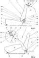
- the rear seat systems 1 shown in Figures 1 and 2 both have a foldable backrest 2.
- this is pivotally mounted in a pivot bearing 4 arranged between the backrest 2 and a seat part 3, so that it faces forward Folded seat part 3 and then optionally together with it about the pivot axis 6 of a second pivot bearing 7 arranged on the lower front edge of the seat part 3 can be pivoted upwards and placed upright in order to enlarge a luggage space 9 arranged behind the rear seat bench 1.
- a pivot bearing 4 arranged between the backrest 2 and a seat part 3
- a pivot bearing 10 is arranged between the backrest 2 and a part 12 of the body in order to fold the backrest 2 forward relative to the body part 12, so that its rear 13 forms an extension of the luggage compartment floor 14 after previously the seat part 3 of the rear seat bench 1 has also been folded forward and placed upright in a second pivot bearing 16 arranged on the lower front edge of the seat part 3.
- the backrest 2 can also be folded forward onto the fixed seat part 3.
- the backrest 2 can be of split design in both exemplary embodiments, in this case in the middle or in the region of the division of the rear seat system 1, a further pivot bearing between the backrest 2 and the seat part 3 (FIG. 1) or between the backrest 2 and the body part 12 (Fig. 2) is arranged to enable a separate folding of the two backrest parts (not shown).
- Two locks 18 are used to lock the backrest 2 in their upright sitting position, which are attached to the opposite outer sides of the backrest 2 and each comprise a locking mechanism 20 integrated in the backrest 2.
- the locking mechanism 20 has a movable locking element 21, which can be locked with a securing element 22, 23, which is firmly connected to the body in the area of one of the two spring strut domes 24 of the motor vehicle.
- a reverse arrangement with a locking mechanism fixed to the body and a securing element integrated into the backrests 2 is, however, also conceivable.
- both the locks 18 and the pivot bearings 4, 10 have deformation elements 25, 26, 27, 28, 29.
- the swivel bearing with the deformation element can also be connected on the body side in the region of the backrest division.
- the outer pivot bearings are then rigid, i. H. designed without energy absorption element.
- the deformation elements 25, 26, 27, 28, 29 are designed such that they plastically deform in a predictable manner when a force acting on the backrest 2 from behind exceeds a predetermined value.
- the deformation elements 25, 26, 27, 28, 29 are plastically deformed, the kinetic energy of the transport objects is at least partially converted into deformation work.
- the deformation elements 25, 26, 27, 28, 29 are arranged so that the backrest 2 moves a little in the direction of travel when they are deformed. The objects to be braked are therefore less abrupt, i.e. with a lower braking acceleration, which results in a reduction in the forces acting on the locks 18 and the pivot bearings 4, 10.
- the deformation element 25, 26, 27, 28 each comprises one or two wave-shaped or zigzag-shaped partial areas which, when a predetermined force is exceeded, are stretched to the rear 13 of the backrest 2 with straightening, whereby the material becomes plastic deformed.
- Fig. 1 shows in the area of the lock 18 a deformation element 25 in the form of a sheet metal strip 30 which is waved in a wave shape transversely to its broad side surface, the flat rear end of which is bent back and down in such a way that it is welded to the upper side of the suspension strut dome 24.
- the front end is also flattened and has a vertical passage opening into which the hook-shaped locking element 21 of the locking mechanism 20 engages in the locked state, as shown.
- the dimensions, the structural design and the material properties of the locking element 21, the locking mechanism 20, as well as all other elements of the lock 18 are selected so that the metal strip 30 forms the weak link in the chain, so to speak, and deforms under stretch before one of the others Elements breaks or tears.
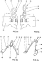
- the deformation element 26 is formed by a wire bracket 32, the two legs 34 of which also have an undulating shape. While the parallel rear ends of the legs 34 are welded to an extension 35 projecting beyond the seat part 3, the bracket 32 is shaped in the region of its yoke so that it encloses an essentially circular receiving opening 36 together with a respective first bending of the legs 34, in which a pivot pin 38 is rotatably mounted.
- the possibly also tubular swivel pin 38 is rigidly connected to a forwardly bent arm 40 of a non-visible cross member running horizontally within the backrest 2 via the rear side 13 thereof and projects laterally beyond the backrest 2.
- the legs 34 are bent twice inwards and once outwards, abutting against one another at the vertices of the inward bends. In principle, however, a different number of wave or zigzag bends can also be provided.
- the deformation element 27 of the pivot bearing 10 also consists of a bracket 33 with wavy legs 34 which are bent in the area of the yoke so that they have an almost closed receiving opening 36 for the over Form backrest 2 protruding pivot pin 38.
- the bracket 33 consists of a sheet metal strip, the ends of which are widened and have through openings 42 for fastening screws. Instead of being fixed by means of fastening screws, there is also a fixing on a body part by means of CO 2 or spot welding or a similar thermal joining process.
- FIG. 3 also shows a deformation element 28 in the form of a wire bracket 35, the legs 34 are bent towards and away from each other in a wave-shaped manner, whereby they are brought together behind the yoke, so that between the yoke and the merging a receiving opening 36 for the free end of the curved locking element 21 of the locking mechanism 20 is formed.
- the locking element 21 can be pivoted against the force of a spring 46 in a vertical plane to release the locking with the aid of a handle knob 45 of the locking mechanism 20 projecting upwards over the backrest 2, while the receiving opening 36 enclosed by the bracket 35 lies essentially in a horizontal plane , so that the free end of the locking element 21 can be pivoted from above into the receiving opening 36 and out of this.
- the parallel rear ends of the legs 34 are welded to the top of the strut dome, possibly also with a separate bearing bolt 24.
- 5b shows the bracket 35 after a frontal impact of the motor vehicle in the course of a dynamic test of the backrest 2 in accordance with DIN 75410, but at a higher impact speed of approximately 50 km / h.
- the legs 34 of the bracket 35 were stretched by the test weight bouncing against the backrest 2, straightening the undulating bends, however, engagement of the locking element 21 (not shown in Fig. 5) is maintained in the yoke.
- the plastic deformation of the deformation element 28 in the exemplary embodiment shown in FIGS. 7 to 9 does not take place by stretching the same, but rather by widening an elongated slot 50 in part of the deformation element 28, with two opposite edges 52 of the slot 50 are pressed apart by a widening body 53 with plastic deformation.
- the deformation element 28 here, too, is not arranged directly in the lock 18 itself, but forms part of the holder of the securing element 23 fixed to the body, which, in contrast to the exemplary embodiment in FIG. 1, is designed as a bolt.
- the bolt 23 projects horizontally over a strip-shaped piece of sheet metal 54, which is displaceably mounted in its longitudinal direction in an elongated receiving holder 56.
- the receptacle bracket 56 is welded to the strut dome 24 at its rearward-facing end and has an essentially C-shaped profile, with its two inwardly bent legs 58 encompassing the sheet metal piece 54 on its long sides.
- the elongated slot 50 is formed in the sheet-metal piece 54 and is provided at its lock-side end with an extension 60 through which the cylindrical expansion body 53, which is rigidly connected to the receiving holder 56, extends.
- the diameter of the expansion body 53 is greater than the width of the slot 50 behind the extension, so that the slot 50 is expanded by the expansion body 53 when the sheet metal piece 54 is displaced longitudinally in the direction of travel as a result of a force acting on the back of the backrest 2, which preferably consists of a harder steel.
- the piece of sheet metal 54 is pressed apart on both sides of the slot 50 with plastic deformation and against the legs 58, which can also be bent slightly.
- the plastic deformation of the edges 52 of the slot 50 and the legs 58 of the receptacle holder 56 causes a conversion of the kinetic energy of the transport objects into deformation work.
- the braking distance of the objects to be transported is also increased, and thus the action of force is reduced.
- the slot 50 can taper somewhat in the direction of the strut mandrel 54, so that the force required for expansion increases as the piece of sheet metal 54 moves.
Landscapes
- Engineering & Computer Science (AREA)
- Aviation & Aerospace Engineering (AREA)
- Transportation (AREA)
- Mechanical Engineering (AREA)
- Seats For Vehicles (AREA)
Priority Applications (1)
| Application Number | Priority Date | Filing Date | Title |
|---|---|---|---|
| DE29623932U DE29623932U1 (de) | 1995-11-20 | 1996-08-30 | Kraftfahrzeug mit einer Rücksitzbank |
Applications Claiming Priority (2)
| Application Number | Priority Date | Filing Date | Title |
|---|---|---|---|
| DE19543173 | 1995-11-20 | ||
| DE19543173 | 1995-11-20 |
Publications (3)
| Publication Number | Publication Date |
|---|---|
| EP0774376A2 true EP0774376A2 (fr) | 1997-05-21 |
| EP0774376A3 EP0774376A3 (fr) | 1998-09-02 |
| EP0774376B1 EP0774376B1 (fr) | 2001-11-07 |
Family
ID=7777887
Family Applications (1)
| Application Number | Title | Priority Date | Filing Date |
|---|---|---|---|
| EP96113881A Expired - Lifetime EP0774376B1 (fr) | 1995-11-20 | 1996-08-30 | Véhicule automobile à banquette arrière |
Country Status (3)
| Country | Link |
|---|---|
| EP (1) | EP0774376B1 (fr) |
| DE (1) | DE59608133D1 (fr) |
| ES (1) | ES2167497T3 (fr) |
Cited By (6)
| Publication number | Priority date | Publication date | Assignee | Title |
|---|---|---|---|---|
| EP0927659A2 (fr) | 1998-01-02 | 1999-07-07 | Volkswagen Aktiengesellschaft | Système de retenue pour un siège d'enfant emporté dans un véhicule automobile |
| EP1258390A1 (fr) * | 2001-05-15 | 2002-11-20 | Bayerische Motoren Werke Aktiengesellschaft | Dossier pour véhicule automobile |
| FR2871865A1 (fr) * | 2004-06-22 | 2005-12-23 | Renault Sas | Dispositif d'articulation en rotation de deux pieces d'un vehicule automobile |
| WO2006063871A1 (fr) * | 2004-06-16 | 2006-06-22 | Johnson Controls Gmbh | Element de vehicule et procede pour empecher, en cas de collision, l'ouverture d'un composant pivotant |
| FR2940936A1 (fr) * | 2009-01-09 | 2010-07-16 | Rehau Sa | Liaison d'absorption d'energie entre un dossier de siege arriere d'un vehicule et son point d'ancrage a la carrosserie |
| DE102012214393A1 (de) * | 2012-06-14 | 2013-12-19 | Keiper Gmbh & Co. Kg | Verriegelungsvorrichtung für eine klappbare Sitzlehne eines Fahrzeugs |
Family Cites Families (7)
| Publication number | Priority date | Publication date | Assignee | Title |
|---|---|---|---|---|
| FR1371788A (fr) * | 1963-04-04 | 1964-09-11 | Dispositif absorbeur de choc et d'énergie d'impact pour véhicules | |
| US3578376A (en) * | 1968-09-20 | 1971-05-11 | Toyota Motor Co Ltd | Seat construction of a vehicle |
| US3730586A (en) * | 1971-11-24 | 1973-05-01 | Budd Co | Decelerating apparatus |
| DE3930137A1 (de) * | 1989-09-09 | 1991-03-21 | Bayer Ag | Stossdaempfer in form eines schockabsorbers |
| GB9225001D0 (en) * | 1992-11-30 | 1993-01-20 | Aircraft Furnishing Ltd | Energy absorber |
| US5639144A (en) * | 1994-06-27 | 1997-06-17 | Ford Motor Company | Energy absorbing child seat fastener |
| FR2728205B1 (fr) * | 1994-12-19 | 1997-02-21 | Faure Bertrand Equipements Sa | Dossier antichoc pour siege de vehicule |
-
1996
- 1996-08-30 ES ES96113881T patent/ES2167497T3/es not_active Expired - Lifetime
- 1996-08-30 DE DE59608133T patent/DE59608133D1/de not_active Expired - Lifetime
- 1996-08-30 EP EP96113881A patent/EP0774376B1/fr not_active Expired - Lifetime
Cited By (8)
| Publication number | Priority date | Publication date | Assignee | Title |
|---|---|---|---|---|
| EP0927659A2 (fr) | 1998-01-02 | 1999-07-07 | Volkswagen Aktiengesellschaft | Système de retenue pour un siège d'enfant emporté dans un véhicule automobile |
| EP1258390A1 (fr) * | 2001-05-15 | 2002-11-20 | Bayerische Motoren Werke Aktiengesellschaft | Dossier pour véhicule automobile |
| WO2006063871A1 (fr) * | 2004-06-16 | 2006-06-22 | Johnson Controls Gmbh | Element de vehicule et procede pour empecher, en cas de collision, l'ouverture d'un composant pivotant |
| FR2871865A1 (fr) * | 2004-06-22 | 2005-12-23 | Renault Sas | Dispositif d'articulation en rotation de deux pieces d'un vehicule automobile |
| EP1630432A1 (fr) * | 2004-06-22 | 2006-03-01 | Renault s.a.s. | Dispositif d'articulation en rotation de deux pièces d'un vehicule automobile |
| FR2940936A1 (fr) * | 2009-01-09 | 2010-07-16 | Rehau Sa | Liaison d'absorption d'energie entre un dossier de siege arriere d'un vehicule et son point d'ancrage a la carrosserie |
| DE102012214393A1 (de) * | 2012-06-14 | 2013-12-19 | Keiper Gmbh & Co. Kg | Verriegelungsvorrichtung für eine klappbare Sitzlehne eines Fahrzeugs |
| DE102012214393B4 (de) * | 2012-06-14 | 2020-09-17 | Adient Luxembourg Holding S.À R.L. | Verriegelungsvorrichtung für eine klappbare Sitzlehne eines Fahrzeugs |
Also Published As
| Publication number | Publication date |
|---|---|
| EP0774376B1 (fr) | 2001-11-07 |
| EP0774376A3 (fr) | 1998-09-02 |
| ES2167497T3 (es) | 2002-05-16 |
| DE59608133D1 (de) | 2001-12-13 |
Similar Documents
| Publication | Publication Date | Title |
|---|---|---|
| DE3544248C1 (de) | Aufblasbares Aufprallschutzkissen | |
| DE10163890B4 (de) | Kopfstützenanordnung | |
| DE60207921T2 (de) | Sitzrückenlehnenrahmen für Fahrzeugsitz | |
| DE60223751T2 (de) | Vorderwagenaufbau für ein Fahrzeug | |
| DE69811639T2 (de) | Unterfahrschutzvorrichtung in fahrzeugen | |
| DE19938937A1 (de) | Karosserieaufbau eines Kraftfahrzeugs mit kontrollierter Reaktionslast | |
| DE2825460A1 (de) | Energieabsorber, insbesondere fuer motorfahrzeuge | |
| EP0927659B1 (fr) | Système de retenue pour un siège d'enfant emporté dans un véhicule automobile | |
| DE19635285A1 (de) | Seitenrahmenstruktur für Fahrzeuge | |
| DE2166310A1 (de) | Ueberrollschutzanordnung fuer fahrzeuge, insbesondere kraftfahrzeuge | |
| DE19613506A1 (de) | Schienenpaar für längseinstellbare Fahrzeugsitze | |
| WO2020002287A1 (fr) | Coussin gonflable pour un système de sécurité pour véhicule d'un véhicule à moteur et module de coussin gonflable | |
| DE2460598A1 (de) | Stossdaempfungsvorrichtung | |
| EP0774376B1 (fr) | Véhicule automobile à banquette arrière | |
| DE69814836T2 (de) | Verstärkungselemente für ein fahrzeug | |
| DE4421946A1 (de) | Rückenlehne eines Kraftfahrzeugsitzes, die aus einem Rückenlehnengestell und einem Polsterteil aufgebaut ist | |
| DE102007062361A1 (de) | Fahrzeugsitz | |
| DE29623932U1 (de) | Kraftfahrzeug mit einer Rücksitzbank | |
| EP1612096A2 (fr) | Agencement de sièges dans un véhicule automobile et sytème de protection des passagers dudit véhicule | |
| DE10145240A1 (de) | Kopfstütze für Fahrzeugsitze | |
| DE102005014401B4 (de) | Lagerung eines kippbaren Fahrerhauses | |
| EP1893471B1 (fr) | Automobile | |
| DE19505160C2 (de) | Fondsitzbank für einen Kombi-Personenkraftwagen | |
| DE4127652A1 (de) | Nach dem stuelpprinzig arbeitendes deformationselement | |
| DE19860674C1 (de) | Lagerung zur drehbeweglichen Anlenkung von Rücksitzlehnen in Kraftfahrzeugen |
Legal Events
| Date | Code | Title | Description |
|---|---|---|---|
| PUAI | Public reference made under article 153(3) epc to a published international application that has entered the european phase |
Free format text: ORIGINAL CODE: 0009012 |
|
| AK | Designated contracting states |
Kind code of ref document: A2 Designated state(s): DE ES FR GB IT |
|
| PUAL | Search report despatched |
Free format text: ORIGINAL CODE: 0009013 |
|
| AK | Designated contracting states |
Kind code of ref document: A3 Designated state(s): DE ES FR GB IT |
|
| 17P | Request for examination filed |
Effective date: 19990302 |
|
| 17Q | First examination report despatched |
Effective date: 20000128 |
|
| GRAG | Despatch of communication of intention to grant |
Free format text: ORIGINAL CODE: EPIDOS AGRA |
|
| GRAG | Despatch of communication of intention to grant |
Free format text: ORIGINAL CODE: EPIDOS AGRA |
|
| GRAG | Despatch of communication of intention to grant |
Free format text: ORIGINAL CODE: EPIDOS AGRA |
|
| GRAH | Despatch of communication of intention to grant a patent |
Free format text: ORIGINAL CODE: EPIDOS IGRA |
|
| GRAH | Despatch of communication of intention to grant a patent |
Free format text: ORIGINAL CODE: EPIDOS IGRA |
|
| GRAA | (expected) grant |
Free format text: ORIGINAL CODE: 0009210 |
|
| AK | Designated contracting states |
Kind code of ref document: B1 Designated state(s): DE ES FR GB IT |
|
| REF | Corresponds to: |
Ref document number: 59608133 Country of ref document: DE Date of ref document: 20011213 |
|
| REG | Reference to a national code |
Ref country code: GB Ref legal event code: IF02 |
|
| ET | Fr: translation filed | ||
| GBT | Gb: translation of ep patent filed (gb section 77(6)(a)/1977) |
Effective date: 20020131 |
|
| REG | Reference to a national code |
Ref country code: ES Ref legal event code: FG2A Ref document number: 2167497 Country of ref document: ES Kind code of ref document: T3 |
|
| PLBE | No opposition filed within time limit |
Free format text: ORIGINAL CODE: 0009261 |
|
| STAA | Information on the status of an ep patent application or granted ep patent |
Free format text: STATUS: NO OPPOSITION FILED WITHIN TIME LIMIT |
|
| 26N | No opposition filed | ||
| PGFP | Annual fee paid to national office [announced via postgrant information from national office to epo] |
Ref country code: DE Payment date: 20140831 Year of fee payment: 19 |
|
| PGFP | Annual fee paid to national office [announced via postgrant information from national office to epo] |
Ref country code: GB Payment date: 20140829 Year of fee payment: 19 Ref country code: ES Payment date: 20140926 Year of fee payment: 19 Ref country code: FR Payment date: 20140827 Year of fee payment: 19 |
|
| PGFP | Annual fee paid to national office [announced via postgrant information from national office to epo] |
Ref country code: IT Payment date: 20140826 Year of fee payment: 19 |
|
| REG | Reference to a national code |
Ref country code: DE Ref legal event code: R119 Ref document number: 59608133 Country of ref document: DE |
|
| GBPC | Gb: european patent ceased through non-payment of renewal fee |
Effective date: 20150830 |
|
| PG25 | Lapsed in a contracting state [announced via postgrant information from national office to epo] |
Ref country code: IT Free format text: LAPSE BECAUSE OF NON-PAYMENT OF DUE FEES Effective date: 20150830 |
|
| REG | Reference to a national code |
Ref country code: FR Ref legal event code: ST Effective date: 20160429 |
|
| PG25 | Lapsed in a contracting state [announced via postgrant information from national office to epo] |
Ref country code: DE Free format text: LAPSE BECAUSE OF NON-PAYMENT OF DUE FEES Effective date: 20160301 Ref country code: GB Free format text: LAPSE BECAUSE OF NON-PAYMENT OF DUE FEES Effective date: 20150830 |
|
| PG25 | Lapsed in a contracting state [announced via postgrant information from national office to epo] |
Ref country code: FR Free format text: LAPSE BECAUSE OF NON-PAYMENT OF DUE FEES Effective date: 20150831 |
|
| REG | Reference to a national code |
Ref country code: ES Ref legal event code: FD2A Effective date: 20160926 |
|
| PG25 | Lapsed in a contracting state [announced via postgrant information from national office to epo] |
Ref country code: ES Free format text: LAPSE BECAUSE OF NON-PAYMENT OF DUE FEES Effective date: 20150831 |