EP0774625A2 - Circuit de commande de combustion d'un appareil à combustion - Google Patents
Circuit de commande de combustion d'un appareil à combustion Download PDFInfo
- Publication number
- EP0774625A2 EP0774625A2 EP96307887A EP96307887A EP0774625A2 EP 0774625 A2 EP0774625 A2 EP 0774625A2 EP 96307887 A EP96307887 A EP 96307887A EP 96307887 A EP96307887 A EP 96307887A EP 0774625 A2 EP0774625 A2 EP 0774625A2
- Authority
- EP
- European Patent Office
- Prior art keywords
- combustion
- signal
- output signal
- state
- exhaust fan
- Prior art date
- Legal status (The legal status is an assumption and is not a legal conclusion. Google has not performed a legal analysis and makes no representation as to the accuracy of the status listed.)
- Withdrawn
Links
- 238000002485 combustion reaction Methods 0.000 title claims abstract description 119
- XLYOFNOQVPJJNP-UHFFFAOYSA-N water Substances O XLYOFNOQVPJJNP-UHFFFAOYSA-N 0.000 claims description 34
- 230000001276 controlling effect Effects 0.000 claims 4
- 238000010438 heat treatment Methods 0.000 claims 3
- 239000000446 fuel Substances 0.000 claims 1
- 239000008236 heating water Substances 0.000 claims 1
- 238000000034 method Methods 0.000 claims 1
- 230000001105 regulatory effect Effects 0.000 claims 1
- 238000010586 diagram Methods 0.000 description 3
- 238000007796 conventional method Methods 0.000 description 2
- 239000000203 mixture Substances 0.000 description 2
- 238000012986 modification Methods 0.000 description 2
- 230000004048 modification Effects 0.000 description 2
- 238000010420 art technique Methods 0.000 description 1
- 230000002939 deleterious effect Effects 0.000 description 1
- 238000002474 experimental method Methods 0.000 description 1
Images

Classifications
-
- F—MECHANICAL ENGINEERING; LIGHTING; HEATING; WEAPONS; BLASTING
- F24—HEATING; RANGES; VENTILATING
- F24H—FLUID HEATERS, e.g. WATER OR AIR HEATERS, HAVING HEAT-GENERATING MEANS, e.g. HEAT PUMPS, IN GENERAL
- F24H1/00—Water heaters, e.g. boilers, continuous-flow heaters or water-storage heaters
-
- F—MECHANICAL ENGINEERING; LIGHTING; HEATING; WEAPONS; BLASTING
- F23—COMBUSTION APPARATUS; COMBUSTION PROCESSES
- F23N—REGULATING OR CONTROLLING COMBUSTION
- F23N5/00—Systems for controlling combustion
- F23N5/02—Systems for controlling combustion using devices responsive to thermal changes or to thermal expansion of a medium
- F23N5/10—Systems for controlling combustion using devices responsive to thermal changes or to thermal expansion of a medium using thermocouples
- F23N5/102—Systems for controlling combustion using devices responsive to thermal changes or to thermal expansion of a medium using thermocouples using electronic means
-
- F—MECHANICAL ENGINEERING; LIGHTING; HEATING; WEAPONS; BLASTING
- F23—COMBUSTION APPARATUS; COMBUSTION PROCESSES
- F23N—REGULATING OR CONTROLLING COMBUSTION
- F23N1/00—Regulating fuel supply
- F23N1/06—Regulating fuel supply conjointly with draught
- F23N1/062—Regulating fuel supply conjointly with draught using electronic means
-
- F—MECHANICAL ENGINEERING; LIGHTING; HEATING; WEAPONS; BLASTING
- F23—COMBUSTION APPARATUS; COMBUSTION PROCESSES
- F23N—REGULATING OR CONTROLLING COMBUSTION
- F23N1/00—Regulating fuel supply
- F23N1/08—Regulating fuel supply conjointly with another medium, e.g. boiler water
- F23N1/10—Regulating fuel supply conjointly with another medium, e.g. boiler water and with air supply or draught
- F23N1/102—Regulating fuel supply conjointly with another medium, e.g. boiler water and with air supply or draught using electronic means
-
- F—MECHANICAL ENGINEERING; LIGHTING; HEATING; WEAPONS; BLASTING
- F23—COMBUSTION APPARATUS; COMBUSTION PROCESSES
- F23N—REGULATING OR CONTROLLING COMBUSTION
- F23N2225/00—Measuring
- F23N2225/08—Measuring temperature
- F23N2225/18—Measuring temperature feedwater temperature
-
- F—MECHANICAL ENGINEERING; LIGHTING; HEATING; WEAPONS; BLASTING
- F23—COMBUSTION APPARATUS; COMBUSTION PROCESSES
- F23N—REGULATING OR CONTROLLING COMBUSTION
- F23N2233/00—Ventilators
- F23N2233/02—Ventilators in stacks
- F23N2233/04—Ventilators in stacks with variable speed
-
- F—MECHANICAL ENGINEERING; LIGHTING; HEATING; WEAPONS; BLASTING
- F23—COMBUSTION APPARATUS; COMBUSTION PROCESSES
- F23N—REGULATING OR CONTROLLING COMBUSTION
- F23N2235/00—Valves, nozzles or pumps
- F23N2235/12—Fuel valves
- F23N2235/16—Fuel valves variable flow or proportional valves
-
- F—MECHANICAL ENGINEERING; LIGHTING; HEATING; WEAPONS; BLASTING
- F23—COMBUSTION APPARATUS; COMBUSTION PROCESSES
- F23N—REGULATING OR CONTROLLING COMBUSTION
- F23N2241/00—Applications
- F23N2241/04—Heating water
-
- F—MECHANICAL ENGINEERING; LIGHTING; HEATING; WEAPONS; BLASTING
- F23—COMBUSTION APPARATUS; COMBUSTION PROCESSES
- F23N—REGULATING OR CONTROLLING COMBUSTION
- F23N5/00—Systems for controlling combustion
- F23N5/18—Systems for controlling combustion using detectors sensitive to rate of flow of air or fuel
Definitions
- the present invention relates to a combustion control circuit of a combustion apparatus used for a boiler, an instant hot-water supply equipment and the like. More particularly, it relates to such a combustion control circuit of a combustion apparatus that may be capable of controlling an exhaust fan and a gas valve by detecting the actual state of combustion within its combustion chamber for the purpose of compensating for a difference between the actual state of combustion and its reference state.
- a combustion apparatus that allows gas to burn to produce heat is generally included in a boiler, an instant hot-water supply equipment and the like.
- the heat produced by the combustion apparatus is used to heat up water for a hot-water boiler or a hot-water supply equipment.
- the calorific power of the combustion apparatus is controlled by changing the amount of gas and air supplied to the combustion apparatus.
- the amount of gas and air supplied to the combustion apparatus should be increased to enhance the calorific power of the combustion apparatus in such a manner that the temperature of water is raised.
- the amount of gas and air supplied to the combustion apparatus is reduced to decrease the calorific power of the combustion apparatus.
- the mixture ratio of applied gas and air should be controlled to make the combustion state optimum. The mixture ratio of gas and air for optimal combustion is determined through experiments.
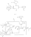
- a conventional combustion control circuit of a combustion apparatus includes, as shown in Fig. 1, a controller 1 that controls the overall circuit, a temperature sensor 2 that senses the temperature of water to produce to the controller 1 an electrical signal corresponding to the temperature of water, and a flow sensor 3 that senses a flow of water to produce to the controller 1 an electrical signal corresponding to the flow of water.
- the conventional combustion control circuit also includes an exhaust fan 4 that is actuated by the controller 1 to provide air whose amount is adequate to the combustion apparatus, and a gas valve 5 that is operated by the controller 1 to provide gas whose amount is adequate to the combustion apparatus.
- the temperature sensor 2 and the flow sensor 3 are provided to the hot-water pipe to sense the temperature of hot water and the flow of water, and the exhaust fan 4 installed in a discharge path of exhaust gas allows the exhaust gas to escape from the combustion apparatus and, at the same time, provides air to the combustion apparatus.
- the gas valve 5 is supplied to a gas pipe connected to the combustion apparatus so as to control the amount of gas.
- the controller 1 receives electrical signals corresponding to the temperature of water and a flow of it from the temperature sensor 2 and the flow sensor 3. Subsequently, the controller 1 allows the exhaust fan 4 and the gas valve 5 to operate in response to the electrical signals produced from the temperature sensor 2 and the flow sensor 3.
- the exhaust fan 4 and the gas valve 5 are controlled according to the difference between the set temperature of water and its actual one that the temperature sensor 2 measures and the flow of water that the flow sensor 3 finds.
- This conventional combustion control circuit controls the exhaust fan 4 and the gas valve 5 without regard to the actual state of combustion that occurs within the combustion chamber, and it is difficult to control the temperature of water to a set point.
- the conventional combustion control circuit has the condition of combustion varied with a change in the condition of using a boiler or hot-water supplier. Thus, the conventional combustion control circuit cannot provide optimum combustion that results in gas deleterious to a human body due to imperfect combustion.
- the present invention relates to a combustion control circuit of a combustion apparatus that substantially obviates one or more of the problems due to limitations and disadvantages of the related art.
- the inventive combustion control circuit of a combustion apparatus having a driving signal generator for producing a driving signal for an exhaust fan and a gas valve in response to each output signal of a temperature sensor and a flow sensor, an exhaust fan controller for outputting a control signal for the exhaust fan in response to the output signal of the driving signal generator, and a gas valve controller for producing a control signal for the gas valve in response to the output signal of the driving signal generator.
- the inventive combustion control circuit includes a combustion state detector for detecting the state of combustion occurring within a combustion chamber according to an output signal of a flame sensor installed in the combustion chamber and for producing a signal corresponding to the state of combustion; a reference signal generator for producing a reference signal in response to each output signal of the temperature sensor and the flow sensor; a comparator for comparing the output signal of the combustion state detector with the output signal of the reference signal generator, and for outputting a signal corresponding to a difference therebetween; and an adder for adding the output signal of the comparator to the output signal of the driving signal generator, and for respectively applying an output to each one of the exhaust fan controller and the gas valve controller.
- a combustion control circuit of a combustion apparatus of the present invention includes driving signal generating means 11 producing a driving signal for an exhaust fan 4 and a gas valve 5 in response to each output signal of a temperature sensor 2 and a flow sensor 3, exhaust fan controlling means 12 outputting a control signal for the exhaust fan 4 in response to the output signal of the driving signal generating means 11, and gas valve controlling means 13 producing a control signal for the gas valve 5 in response to the output signal of the driving signal generating means 11.
- the combustion control circuit of the present invention further comprises combustion state detecting means 14 for detecting the state of combustion occurring within a combustion chamber according to an output signal of a flame sensor 6 installed in the combustion chamber, and for producing a signal corresponding to the state of combustion; reference signal generating means 15 for producing a reference signal in response to each one of the output signals of the temperature sensor 2 and the flow sensor 3; comparing means 16 for comparing the output signal of the combustion state detecting means 14 with the output signal of the reference signal generating means 15, and for outputting a signal corresponding to a difference therebetween; and adding means 17 for adding the output signal of the comparing means to the output signal of the driving signal generating means 11 and for respectively applying an output to each one of the exhaust fan controlling means 12 and the gas valve controlling means 13.
- the combustion control circuit of the present invention constructed as above operates as below.
- Driving signal generator 11 produces a driving signal for controlling exhaust fan 4 and gas valve 5 in response to signals generated from temperature sensor 2 and flow sensor 3, like that of a conventional art technique.
- the driving signal is not directly applied to exhaust fan controller 12 and gas valve controller 13 but is compensated according to the state of combustion to be input to the exhaust fan controller 12 and the gas valve controller 13.
- Combustion state detector 14 detects a signal corresponding to the combustion of state in response to a signal produced from flame sensor 6, and the better the state of combustion is, the higher a voltage signal generated by the combustion state detector 14 becomes in level.
- Reference signal generator 15 produces a reference signal in response to each signal produced from the temperature sensor 2 and the flow sensor 3. The higher each level of the signals generated from the temperature sensor 2 and the flow sensor 3 is (a voltage signal produced from the temperature sensor attains a high level in inverse proportion to the temperature of water), the higher a voltage of the reference signal produced from the reference signal generator 15 becomes.
- Comparator 16 compares an output signal of the combustion state detector 14 with that of the reference signal generator 15, and produces a signal corresponding to the difference therebetween. If the signal of the combustion state detector 14 is higher in level than that of the reference signal generator 15, the comparator 16 generates a signal attaining a negative level, and if the signal of the combustion state detector 14 is lower in level than that of the reference signal generator 15, the comparator 16 generates a signal that attains a positive level.
- Adder 17 adds a signal produced from the driving signal generator 11 to that from the comparator 16, and produces an output to each one of the exhaust fan controller 12 and the gas valve controller 13.
- the state of combustion is too good ((violent)
- the signal produced from the comparator 16 attains a negative level
- the adder 17 controls the output signal of the driving signal generator 11 to a low level.
- the state of combustion is not good (weak)
- the signal produced from the comparator 16 attains a positive level
- the adder 17 controls the output signal of the driving signal generator 11 to a high level.
- the present invention when the state of combustion within the combustion chamber is too good, the present invention reduces the amount of air and gas that are respectively supplied by the exhaust fan 4 and the gas valve 5, and when the state of combustion within the combustion chamber is not good, the present invention increases the amount of air and gas that are respectively supplied by the exhaust fan 4 and the gas valve 5 so that the combustion apparatus can have an adequate calorific value.
- the present invention detects the actual state of combustion, and controls the exhaust fan 4 and the gas valve 5 so as to compensate for a difference between a reference combustion state and the actual state thereof, which makes possible exactly controlling the temperature of water to a set point.
Landscapes
- Engineering & Computer Science (AREA)
- Chemical & Material Sciences (AREA)
- Combustion & Propulsion (AREA)
- Mechanical Engineering (AREA)
- General Engineering & Computer Science (AREA)
- Physics & Mathematics (AREA)
- Thermal Sciences (AREA)
- Control Of Combustion (AREA)
- Regulation And Control Of Combustion (AREA)
- Feeding And Controlling Fuel (AREA)
- Fluidized-Bed Combustion And Resonant Combustion (AREA)
Applications Claiming Priority (2)
| Application Number | Priority Date | Filing Date | Title |
|---|---|---|---|
| KR1019950042316A KR0167837B1 (ko) | 1995-11-20 | 1995-11-20 | 연소기기의 연소제어회로 |
| KR9542316 | 1995-11-20 |
Publications (2)
| Publication Number | Publication Date |
|---|---|
| EP0774625A2 true EP0774625A2 (fr) | 1997-05-21 |
| EP0774625A3 EP0774625A3 (fr) | 1998-04-22 |
Family
ID=19434749
Family Applications (1)
| Application Number | Title | Priority Date | Filing Date |
|---|---|---|---|
| EP96307887A Withdrawn EP0774625A3 (fr) | 1995-11-20 | 1996-10-31 | Circuit de commande de combustion d'un appareil à combustion |
Country Status (5)
| Country | Link |
|---|---|
| US (1) | US5775236A (fr) |
| EP (1) | EP0774625A3 (fr) |
| JP (1) | JPH09170756A (fr) |
| KR (1) | KR0167837B1 (fr) |
| AU (1) | AU680798B2 (fr) |
Families Citing this family (2)
| Publication number | Priority date | Publication date | Assignee | Title |
|---|---|---|---|---|
| US10612795B2 (en) | 2016-09-14 | 2020-04-07 | Lochinvar, Llc | Methods and system for demand-based control of a combination boiler |
| KR102907463B1 (ko) | 2023-11-27 | 2026-01-08 | (주)에스앤테크 | 가스 감지기의 가스 감지 방법 |
Family Cites Families (16)
| Publication number | Priority date | Publication date | Assignee | Title |
|---|---|---|---|---|
| US4133629A (en) * | 1977-08-02 | 1979-01-09 | Phillips Petroleum Company | Combustion system control |
| JPS6021294B2 (ja) * | 1979-03-07 | 1985-05-27 | 株式会社日立製作所 | 燃焼制御回路 |
| US4375950A (en) * | 1981-04-01 | 1983-03-08 | Durley Iii Benton A | Automatic combustion control method and apparatus |
| US4588372A (en) * | 1982-09-23 | 1986-05-13 | Honeywell Inc. | Flame ionization control of a partially premixed gas burner with regulated secondary air |
| NL8403840A (nl) * | 1984-12-18 | 1986-07-16 | Tno | Inrichting voor het regelen van de gasbrandstof-luchtverhouding in een brander van een gasgestookte ketel. |
| JP2531230B2 (ja) * | 1988-02-26 | 1996-09-04 | 株式会社ノーリツ | 比例制御バ―ナの空燃比制御装置 |
| JPH01256717A (ja) * | 1988-04-04 | 1989-10-13 | Yamatake Honeywell Co Ltd | 燃焼制御装置 |
| FR2638819A1 (fr) * | 1988-11-10 | 1990-05-11 | Vaillant Sarl | Procede et un dispositif pour la preparation d'un melange combustible-air destine a une combustion |
| JPH033795U (fr) * | 1989-06-02 | 1991-01-16 | ||
| JPH0721790Y2 (ja) * | 1989-06-29 | 1995-05-17 | タキゲン製造株式会社 | 扉用ハンドル装置 |
| JPH03156209A (ja) * | 1989-11-10 | 1991-07-04 | Toshiba Corp | 燃焼制御装置 |
| JPH0814369B2 (ja) * | 1991-03-26 | 1996-02-14 | 川崎重工業株式会社 | 石炭燃焼炉の燃焼制御装置 |
| JPH04347410A (ja) * | 1991-05-24 | 1992-12-02 | Matsushita Electric Ind Co Ltd | 燃焼器の着火制御装置 |
| JP3345964B2 (ja) * | 1993-06-11 | 2002-11-18 | 松下電器産業株式会社 | 燃焼装置 |
| US5526776A (en) * | 1995-03-30 | 1996-06-18 | Frontier, Inc. | Gas quick water heater |
| US5503183A (en) * | 1995-06-07 | 1996-04-02 | Frontier, Inc. | Hot-water thermoregulating valve |
-
1995
- 1995-11-20 KR KR1019950042316A patent/KR0167837B1/ko not_active Expired - Fee Related
-
1996
- 1996-10-31 EP EP96307887A patent/EP0774625A3/fr not_active Withdrawn
- 1996-11-01 AU AU70545/96A patent/AU680798B2/en not_active Ceased
- 1996-11-12 US US08/745,703 patent/US5775236A/en not_active Expired - Fee Related
- 1996-11-20 JP JP8309254A patent/JPH09170756A/ja active Pending
Non-Patent Citations (1)
| Title |
|---|
| None |
Also Published As
| Publication number | Publication date |
|---|---|
| EP0774625A3 (fr) | 1998-04-22 |
| KR0167837B1 (ko) | 1998-12-15 |
| KR970028228A (ko) | 1997-06-24 |
| AU7054596A (en) | 1997-05-29 |
| JPH09170756A (ja) | 1997-06-30 |
| US5775236A (en) | 1998-07-07 |
| AU680798B2 (en) | 1997-08-07 |
Similar Documents
| Publication | Publication Date | Title |
|---|---|---|
| US6257870B1 (en) | Gas furnace with variable speed draft inducer | |
| US4852797A (en) | Process for operating a fuel-operated heater and control arrangement for performing the process | |
| US5713515A (en) | Method and system in a fluid heating apparatus for efficiently controlling combustion | |
| US5775236A (en) | Combustion control circuit of combustion apparatus | |
| JPH10267265A (ja) | ガスボイラーの空気対ガス比制御装置及びその方法 | |
| JPS634096B2 (fr) | ||
| KR910002734B1 (ko) | 연소제어장치 | |
| US6050807A (en) | Method and apparatus for controlling an amount of air of a gas boiler | |
| KR100243899B1 (ko) | 가스보일러의 연소제어방법 | |
| JP2933876B2 (ja) | 多缶設置ボイラの運転制御方法 | |
| KR930005461B1 (ko) | 고출력 가스보일러에서의 난방작동시 연소 제어방법 및 그 장치 | |
| JP3769660B2 (ja) | 給湯器 | |
| JPH0692837B2 (ja) | 給湯器の燃焼制御装置 | |
| JP2960607B2 (ja) | 熱電併給装置 | |
| JP2600915B2 (ja) | 給湯装置 | |
| KR940004177B1 (ko) | 가열 제어장치 | |
| KR100345610B1 (ko) | 보일러의 연소 제어 방법 | |
| JP3091781B2 (ja) | 給湯器のための湯温制御装置 | |
| JPH0747994B2 (ja) | 比例制御弁の制御装置 | |
| JP2593575B2 (ja) | 熱電併給装置 | |
| KR19990002327A (ko) | 온수유량에 따른 온수온도제어방법 | |
| JPH06180102A (ja) | ボイラの給水量制御装置 | |
| RU1802261C (ru) | Способ регулировани уровн в регенеративном подогревателе паровой турбины | |
| JP3122525B2 (ja) | 燃焼装置およびその燃焼制御方法 | |
| JPH0449478Y2 (fr) |
Legal Events
| Date | Code | Title | Description |
|---|---|---|---|
| PUAI | Public reference made under article 153(3) epc to a published international application that has entered the european phase |
Free format text: ORIGINAL CODE: 0009012 |
|
| AK | Designated contracting states |
Kind code of ref document: A2 Designated state(s): DE FR GB IT |
|
| PUAL | Search report despatched |
Free format text: ORIGINAL CODE: 0009013 |
|
| AK | Designated contracting states |
Kind code of ref document: A3 Designated state(s): DE FR GB IT |
|
| STAA | Information on the status of an ep patent application or granted ep patent |
Free format text: STATUS: THE APPLICATION IS DEEMED TO BE WITHDRAWN |
|
| 18D | Application deemed to be withdrawn |
Effective date: 19981023 |