EP0775302B1 - Verfahren und vorrichtung zum messen des drehmomentes eines thermischen internen verbrennungsmotors - Google Patents
Verfahren und vorrichtung zum messen des drehmomentes eines thermischen internen verbrennungsmotors Download PDFInfo
- Publication number
- EP0775302B1 EP0775302B1 EP96922077A EP96922077A EP0775302B1 EP 0775302 B1 EP0775302 B1 EP 0775302B1 EP 96922077 A EP96922077 A EP 96922077A EP 96922077 A EP96922077 A EP 96922077A EP 0775302 B1 EP0775302 B1 EP 0775302B1
- Authority
- EP
- European Patent Office
- Prior art keywords
- engine
- durations
- markers
- packets
- term
- Prior art date
- Legal status (The legal status is an assumption and is not a legal conclusion. Google has not performed a legal analysis and makes no representation as to the accuracy of the status listed.)
- Expired - Lifetime
Links
- 238000002485 combustion reaction Methods 0.000 title claims description 76
- 238000005259 measurement Methods 0.000 title claims description 75
- 238000000034 method Methods 0.000 title claims description 36
- 238000004364 calculation method Methods 0.000 claims description 60
- 238000004458 analytical method Methods 0.000 claims description 26
- 238000004880 explosion Methods 0.000 claims description 19
- 238000012937 correction Methods 0.000 claims description 17
- 230000004044 response Effects 0.000 claims description 17
- 239000000203 mixture Substances 0.000 claims description 11
- 238000005086 pumping Methods 0.000 claims description 10
- 230000000694 effects Effects 0.000 claims description 6
- 238000004519 manufacturing process Methods 0.000 claims description 5
- 238000012545 processing Methods 0.000 claims description 4
- 239000000470 constituent Substances 0.000 claims description 3
- 239000003550 marker Substances 0.000 claims description 3
- 230000000717 retained effect Effects 0.000 claims 3
- 239000007789 gas Substances 0.000 description 31
- 230000006835 compression Effects 0.000 description 13
- 238000007906 compression Methods 0.000 description 13
- 238000012546 transfer Methods 0.000 description 6
- 241000897276 Termes Species 0.000 description 5
- 230000008901 benefit Effects 0.000 description 4
- 230000008569 process Effects 0.000 description 4
- 238000007493 shaping process Methods 0.000 description 4
- 239000007787 solid Substances 0.000 description 4
- 238000010586 diagram Methods 0.000 description 3
- 230000010355 oscillation Effects 0.000 description 3
- 230000001052 transient effect Effects 0.000 description 3
- 238000009530 blood pressure measurement Methods 0.000 description 2
- 230000007423 decrease Effects 0.000 description 2
- 230000001419 dependent effect Effects 0.000 description 2
- 238000002360 preparation method Methods 0.000 description 2
- 239000010453 quartz Substances 0.000 description 2
- VYPSYNLAJGMNEJ-UHFFFAOYSA-N silicon dioxide Inorganic materials O=[Si]=O VYPSYNLAJGMNEJ-UHFFFAOYSA-N 0.000 description 2
- 230000007704 transition Effects 0.000 description 2
- XUIMIQQOPSSXEZ-UHFFFAOYSA-N Silicon Chemical compound [Si] XUIMIQQOPSSXEZ-UHFFFAOYSA-N 0.000 description 1
- 241001080024 Telles Species 0.000 description 1
- 230000001133 acceleration Effects 0.000 description 1
- 238000013459 approach Methods 0.000 description 1
- 230000005540 biological transmission Effects 0.000 description 1
- 150000001875 compounds Chemical class 0.000 description 1
- 239000013256 coordination polymer Substances 0.000 description 1
- 230000003247 decreasing effect Effects 0.000 description 1
- 238000006073 displacement reaction Methods 0.000 description 1
- 239000000446 fuel Substances 0.000 description 1
- 230000006870 function Effects 0.000 description 1
- 239000008246 gaseous mixture Substances 0.000 description 1
- 238000002347 injection Methods 0.000 description 1
- 239000007924 injection Substances 0.000 description 1
- 238000000691 measurement method Methods 0.000 description 1
- 238000012986 modification Methods 0.000 description 1
- 230000004048 modification Effects 0.000 description 1
- 239000007800 oxidant agent Substances 0.000 description 1
- 230000002040 relaxant effect Effects 0.000 description 1
- 229910052710 silicon Inorganic materials 0.000 description 1
- 239000010703 silicon Substances 0.000 description 1
- 230000009897 systematic effect Effects 0.000 description 1
Images


Classifications
-
- G—PHYSICS
- G01—MEASURING; TESTING
- G01M—TESTING STATIC OR DYNAMIC BALANCE OF MACHINES OR STRUCTURES; TESTING OF STRUCTURES OR APPARATUS, NOT OTHERWISE PROVIDED FOR
- G01M15/00—Testing of engines
- G01M15/04—Testing internal-combustion engines
- G01M15/042—Testing internal-combustion engines by monitoring a single specific parameter not covered by groups G01M15/06 - G01M15/12
- G01M15/046—Testing internal-combustion engines by monitoring a single specific parameter not covered by groups G01M15/06 - G01M15/12 by monitoring revolutions
-
- G—PHYSICS
- G01—MEASURING; TESTING
- G01L—MEASURING FORCE, STRESS, TORQUE, WORK, MECHANICAL POWER, MECHANICAL EFFICIENCY, OR FLUID PRESSURE
- G01L3/00—Measuring torque, work, mechanical power, or mechanical efficiency, in general
-
- G—PHYSICS
- G01—MEASURING; TESTING
- G01M—TESTING STATIC OR DYNAMIC BALANCE OF MACHINES OR STRUCTURES; TESTING OF STRUCTURES OR APPARATUS, NOT OTHERWISE PROVIDED FOR
- G01M15/00—Testing of engines
- G01M15/04—Testing internal-combustion engines
- G01M15/11—Testing internal-combustion engines by detecting misfire
-
- F—MECHANICAL ENGINEERING; LIGHTING; HEATING; WEAPONS; BLASTING
- F02—COMBUSTION ENGINES; HOT-GAS OR COMBUSTION-PRODUCT ENGINE PLANTS
- F02D—CONTROLLING COMBUSTION ENGINES
- F02D2200/00—Input parameters for engine control
- F02D2200/02—Input parameters for engine control the parameters being related to the engine
- F02D2200/10—Parameters related to the engine output, e.g. engine torque or engine speed
- F02D2200/1002—Output torque
-
- F—MECHANICAL ENGINEERING; LIGHTING; HEATING; WEAPONS; BLASTING
- F02—COMBUSTION ENGINES; HOT-GAS OR COMBUSTION-PRODUCT ENGINE PLANTS
- F02D—CONTROLLING COMBUSTION ENGINES
- F02D2200/00—Input parameters for engine control
- F02D2200/02—Input parameters for engine control the parameters being related to the engine
- F02D2200/10—Parameters related to the engine output, e.g. engine torque or engine speed
- F02D2200/1015—Engines misfires
Definitions
- the invention relates to a method and a device. for measuring the torque of a combustion engine internal and more specifically to improvements to method and device for measuring such a torque described in French patent N ° 91 11273 filed by the plaintiff.
- this same patent proposes, for decrease computation times, group n marks of an angular interval of combustions in three or four packets and calculate the term D referred higher from the scrolling times of these packets in front of the sensor.
- a first object of the invention is to propose a simplified term calculation method and device D, using a small number of packets of benchmarks and producing a result noticeably identical to that provided by the initial calculation method, while dramatically decreasing the numbers of mathematical operations performed.
- a second object of the invention is to propose a additional process and device either basic process described in the patent referred to above, either the method and the device according to the first object of the present invention, to measure variations in low frequency of the resistive torque applied to the motor to allow a quality factor to be assigned to the torque measurement performed.
- a third object of the invention relates to a method and a device derived from the previous ones, to correct the low frequency disturbances suffered by the engine torque, especially those provided by vehicle oscillations or by modifications sudden load.
- a fourth object of the invention is to propose a method and device for performing a new correction integrating the effects of the wealth of the mixture of exhaust gas recirculation rate and transient engine speeds.
- This new correction may or may not be combined with above-mentioned corrections.
- the value obtained for the term D is substantially identical to that initially obtained and this although the number of arithmetic operations to be performed has been reduced to four. This greatly reduces the specifications of the microprocessor used for the realization of calculations. Furthermore, it will be noted now that the practical forms of implementing the processes according to invention are determined by analysis systematic mathematical equivalents of the initial relation which defines D.
- This second form has the advantage of better discerning the late combustions of engine misfires.
- the ends of this horizon correspond to dead centers for all the cylinders.
- the torque exerted on the crankshaft by the pressure prevailing in the cylinders is therefore zero since the lever arms are zero at this instant.
- the load applied to the crankshaft can then be calculated by measuring the acceleration of the flywheel around these dead centers.
- the corrected mean gas torque Cg c calculated from the corrected term Q c is insensitive to low frequency variations of the resisting torque as long as the approximation of this torque by a parabola remains valid at inside the measurement horizon.
- the term ⁇ Cg can obviously be produced independently of the term D. In this case, it constitutes a negative factor of quality of the couple Cg, whatever the way in which this couple is calculated.
- H n ' - ⁇ .R NOT (Pc n'-2 + Pc n'-1 ) + ⁇ . (Pc n'-2 - Pa).
- the torque exerted by the gas pressure on the crankshaft is the compound of the torque exerted by the cylinder in relaxation and the torque exerted by the cylinder in compression.
- the two couples relaxing and compression are adiabatic, therefore identical to a factor k near (k increases when the energy of combustion, therefore wealth increases).
- the gas torque is the sum of the expansion torque, the compression torque (negative because resistant) and the pumping torque.
- Pc being the pressure in the intake manifold and Pa the atmospheric pressure, we can consider that the pumping torque is proportional to (Pc - Pa).
- the compression torque C comp can be calculated from the mass of air introduced into the cylinder, which can be deduced either from a flow measurement or from a pressure measurement.
- the torque C comp is the compression torque of the cylinder which will be in expansion at the time of the measurement (pressure Pc (n-2) ) while for Cg the measured gas torque, the torque is measured C comp of the cylinder in compression at the time of measurement (pressure Pc (n-1) ).
- the filling coefficient can be the same for the two cylinders because the engine speed varies little.
- R N .Pc represents the mass of air introduced into the cylinder. It can therefore be replaced by another estimator Da / N, with Da the mass flow rate of air in the manifold and N the number of revolutions per second of the crankshaft.
- the term (Pc - Pa) can be replaced by (DT - M 0 ) with M 0 , the mass of air introduced into a cylinder for a butterfly at full opening.
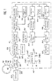
- FIG. 1 there is shown a circuit 10 for measuring the average gas torque Cg c , corrected for low frequency disturbances produced by each combustion of the gas mixture in a four-stroke, four-cylinder thermal engine, equipped with a measuring crown. toothed 12 secured to the flywheel of an electronic ignition engine.
- the crown 12 has on its periphery fifty-six identical regularly spaced teeth such as that formed by the solid 14 and the hollow 16, distributed in two series of twenty-eight teeth separated by two diametrically opposite reference teeth, such as that formed by the solid 18 and the hollow 20, which have a width twice that of the other teeth.
- the two broad diametrically opposite teeth serve as a reference or origin of indexing in order to allow the numbering of each of the teeth and in particular to identify the tooth d o which will be defined below.
- a fixed sensor 22 by example with variable reluctance, suitable for delivering a alternating signal 24 of frequency proportional to the running speed of the teeth of the crown, i.e. proportional to the instantaneous speed of the wheel.
- the angular position of this sensor 22 relative to the indexing teeth 18 at the time when the piston of a cylinder is in top dead center is known or noted. This makes it possible to identify the tooth d o as being that which passes in front of the sensor during the passage of the piston of the cylinder concerned to its top dead center of combustion.
- the signal delivered by the sensor 22 is applied to the input of a shaping circuit 26 adapted to deliver signals 28 with steep sides, of period equal to the instantaneous period d i of the incident signals 24, the indicated i varying from 0 to 29 as the teeth pass in front of the sensor.
- Each period d i of the signal thus produced corresponds to the duration of passage of a tooth, ie a full and a hollow, in front of the sensor 22.
- the setting circuit in form 26 transforms them in the same way into a signal with steep sides, of duration exactly double that of the signals relating to the other teeth.
- the signals 28 are applied to a stage 30 for measuring and calculating the instantaneous periods d i of movement of the real and virtual teeth of the measuring crown 12 in front of the sensor 22.
- the measurement and calculation stage 30 comprises counting circuits which receive high frequency chronometric pulses (10 MHz for example) produced by a quartz clock 32 and it outputs digital values representative of the pulses d clock counted between two hollow-full transitions of the signals with steep sides produced by the shaping stage 26.
- high frequency chronometric pulses (10 MHz for example
- quartz clock 32 outputs digital values representative of the pulses d clock counted between two hollow-full transitions of the signals with steep sides produced by the shaping stage 26.
- the buffer memory 34 is connected to a computation stage 36 adapted to group together in packs of five the thirty instantaneous durations d i comprised between two reference teeth. In this way, the stage 36 successively produces six running times of packets of five reference teeth, respectively numbered 0 , ..., 5 as they are produced. These six durations and their six rank numbers are represented in line I of FIG. 3. These durations and these numbers are then transmitted to a buffer memory 38 placed under the control of a transfer control stage 40 adapted moreover to receive the durations of 0 , ..., of 5 and identify the rank of the duration of 0 .
- the buffer memory 38 is adapted to contain three successive sequences of six durations of reference packets: a central series which defines the measurement horizon being analyzed, a front series which precedes this central series in time and a series rear following it.
- the transfer control stage 40 On the arrival of a new duration of 0 , the transfer control stage 40 is adapted to transfer to the following stages the six durations referenced from 0 , ..., 5 of the central suite as well as, under the reference from -1 , the duration of the 5 of the last packet of the previous sequence and under the reference of +1 , the duration of the 0 of the first packet of the sequence which has just arrived. This is shown in line II of Figure 3.
- a first calculation stage 42 which receives these eight successive durations is programmed to select the six durations referenced from 0 , ... to 5 and to calculate the sum thereof, which is the instantaneous period T of an angular interval of combustions. Each new value T thus calculated is sent to a buffer memory 44 where it replaces the previously calculated value.
- the terms Q and q thus calculated are sent to a buffer memory 48 in which they remain until the arrival of new values of Q and q.
- this value Cg c thus calculated is only valid for engines with two or four cylinders, in which the top or bottom dead centers occur every revolution or every crankshaft U-turns depending on whether they are two-stroke or four-stroke.
- the corrected mean gas torque Cg c Q + q
- the frequency response of the term D, obtained by the simplified calculation mode has maxima of amplitude much higher than those of the term D obtained by the initial calculation mode. This means that disturbances at high frequencies are taken into account more by the simplified calculation mode than by the initial mode.
- This second form has the advantage of better discerning the late combustions of engine misfires.
- the invention is not limited to the embodiment described with reference to FIG. 1 and to lines I and II of FIG. 3. Indeed, it is possible to replace the eight weighted durations of the reference packets of the line II of FIG. 3 by the other eight weighted durations of line III of this same figure.
- the durations not taken into account in the calculation of Q ' c', namely 1 and 4 concern six teeth and the other durations, seven teeth.
- the durations of 0 and 5 each relate to two teeth within the angular interval separating two consecutive top dead centers and five teeth outside this interval.
- the preparation of the quantities necessary for the calculation of the angular period T of the engine combustions will be modified to take into account the fact that the measurement horizon overflows on both sides. other the angular interval concerned.
- This preparation will consist in calculating in addition to the durations necessary for the calculation of Q 'and Q' c ' durations of 0t and 5t (for the example of line III) or 3t (for that of line IV) which are durations of 0 , 5 or 3 truncated limited to only the teeth included in this angular interval.
- the stage 36 for measuring the durations of the packets and for identifying their ranks described above will additionally calculate these truncated durations and assign them an adequate identification.
- the stage 42 for calculating the period T will be programmed accordingly.
- the angular interval defining the width of the packets of rank 0 and n ' determines the precision of the measurement of ⁇ Cg. When this interval is relatively small, this precision decreases. When it becomes relatively large, the measurement becomes sensitive to the pressures in the cylinders. This is because the lever arms of the connecting rods are no longer negligible and, in this case, the packet of rank n 'of the measurement horizon previously analyzed (its duration is referenced from -1 ) and that of rank 0 from the next horizon (its duration is referenced by +1 ) are significantly distant from the two consecutive high dead centers which determine the theoretical boundaries of the measurement horizon being analyzed.
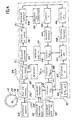
- FIG. 4 there is shown a circuit 10 for measuring the average gas torque corrected first of all at low and high frequency disturbances produced by each combustion of the gas mixture in a four-stroke and four-cylinder thermal engine operating at low and high speed (Cg c1 ) and, secondly, disturbances affecting the measurement due to the specific conditions of combustion in the engine (Cg c2 ).
- a toothed measuring crown 12 is mounted integral with the flywheel of an electronic ignition engine.
- the crown 12 has on its periphery fifty-six identical regularly spaced teeth, such as that formed by the solid 14 and the hollow 16, distributed in two series of twenty-eight teeth separated by two diametrically opposite reference teeth , such as that formed by the solid 18 and the hollow 20, which have a width twice that of the other teeth.
- the two broad diametrically opposite teeth serve as a reference or origin of indexing in order to allow the numbering of each of the teeth and in particular to identify the tooth d o which will be defined below.
- a fixed sensor 22 by example with variable reluctance, suitable for delivering a alternating signal 24 of frequency proportional to the running speed of the teeth of the crown, i.e. proportional to the instantaneous speed of the wheel.
- the angular position of this sensor 22 relative to the indexing teeth 18 at the time when the piston of a cylinder is in top dead center is known or noted. This makes it possible to identify the tooth d o as being that which passes in front of the sensor during the passage of the piston of the cylinder concerned to its top dead center of combustion.
- the signal delivered by the sensor 22 is applied to the input of a shaping circuit 26 adapted to deliver signals 28 with steep sides, of duration equal to the instantaneous period d i of the incident signals 24, the index i varying from 0 to 29 as the teeth pass in front of the sensor.
- Each period d i of the signal thus produced corresponds to the duration of passage of a tooth, ie a full and a hollow, in front of the sensor 22.
- the setting circuit in form 26 transforms them in the same way into a signal with steep sides, of duration exactly double that of the signals relating to the other teeth.
- the signals 28 are applied to a stage 30 for measuring and calculating the instantaneous periods d i of movement of the real and virtual teeth of the measuring crown 12 in front of the sensor 22.
- the measurement and calculation stage 30 comprises counting circuits which receive high frequency chronometric pulses (10 MHz for example) produced by a quartz clock 32 and it outputs digital values representative of the pulses d clock counted between two hollow-full transitions of the signals with steep sides produced by the shaping stage 26.
- high frequency chronometric pulses (10 MHz for example
- quartz clock 32 outputs digital values representative of the pulses d clock counted between two hollow-full transitions of the signals with steep sides produced by the shaping stage 26.
- the buffer memory 34 is connected to a computation stage 36 adapted to group together in packs of five the thirty instantaneous durations d i comprised between two reference teeth.
- the stage 36 successively produces six running times of packets of five reference teeth, respectively numbered 0 , ..., 5 as they are produced, the angular value of each packet being ⁇ / 6, these durations and these numbers are then transmitted to a buffer memory 38 placed under the control of a transfer control stage 40 adapted moreover to receive the durations of 0 .
- the buffer memory 38 is adapted to contain three successive sequences of six durations of reference packets: a central series which defines the measurement horizon being analyzed, a front series which precedes this central series in time and a series rear following it.
- the transfer control stage 40 On the arrival of a new duration of 0 , the transfer control stage 40 is adapted to transfer to the following stages the six durations referenced from 0 , ..., 5 of the central suite as well as, under the reference from -1 , the duration of the 5 of the last packet in the suite before and under the reference of +1 , the duration of the 0 of the first packet of the suite that has just arrived.
- a first calculation stage 42 which receives these eight successive durations is programmed to select the six durations referenced from 0 , ... to 5 and to calculate the sum thereof, which is the instantaneous period T of an angular interval of combustions. Each new value T thus calculated is sent to a buffer memory 44 where it replaces the previously calculated value.
- a second calculation stage 46 which receives these eight successive durations (from -1 , 0 , ..., 5 , +1 ) is programmed to select the following six durations: from -1 , from 0 , from 2 , of 3 , 5 and +1 and to combine them according to the relation: Q vs : 2of 0 - of -1 - of 2 + 2of 5 - of 3 - of +1 .
- the term Q c thus calculated is sent to a buffer memory 48 in which it remains until the arrival of a new value of Q c .
- the embodiment shown in FIG. 4 further comprises an atmospheric pressure sensor 58 Pa, a pressure sensor 60 Pc in the air intake manifold, and a buffer memory 62 to which are applied the data produced by the pressure sensors 58-60.
- These two pressure sensors will, for example, be of the type with strain gauges diffused in a silicon wafer. They first produce an analog quantity representative of the pressure measured. This quantity is then converted into a digital value by an incorporated analog / digital converter before being applied to the buffer memory 62.
- This buffer memory 62 is adapted to hold at any time three successive measurements of the pressure Pc, made at during three successive combustion intervals.
- a last calculation stage 68 receives, on the one hand, the value Cg c1 produced by the calculation stage 54 and, on the other hand, the value of the term H n ' calculated by the calculation stage 64 as well as a constant h also stored in the memory 66.
- the quantity Cg cn'2 thus obtained is the fully corrected numerical value of the torque of an internal combustion engine, of the four-stroke, four-cylinder and injection type, which operates at low and high revs, this value being, in fact, further corrected for low frequency disturbances affecting the engine as well as errors caused by the specific conditions of combustion in the engine (exhaust gas recirculation rate, residual gas rate, excess oxidizer and transient regimes).
- the invention can be implemented from a measurement of air flow in the manifold, instead of a pressure measurement. The particular means of implementing this variant are shown in FIG. 5.
- a mass flow sensor 70 is placed in the air intake manifold.
- This sensor 70 will, for example, be of the hot wire or elastic blade type embedded at one end.
- the sensitive elements of these sensors are mounted in a bridge, so as to first produce an analog signal which an incorporated analog / digital converter then transforms into digital magnitude.
- This digital quantity is applied to a buffer memory 72, which is adapted to hold at any time three data D n ' , D n'-1 and D n'-2 representative respectively of the air flows in the intake manifold , during the combustion interval of rank n 'being analyzed and of the two combustion intervals preceding it in time.
- the data stored in the buffer memory 72 are applied to a calculation stage 74 also receiving from the buffer memory 44, the period T of the combustion interval being analyzed (this period is practically constant during the three successive periods concerned).
- the data D n'-2 stored in the buffer memory 72 is applied to a calculation stage 78 adapted to calculate (D n'-2 .T - M 0 ) from D n'-2 and from M 0 , the mass of air introduced into a cylinder for a fully open throttle valve, which is a measured constant, stored in a permanent memory 80.
- the term (D n'-2 .T - M 0 ) thus calculated is CP (n'-2) . This term is then applied to a buffer memory 82.
- a permanent memory 84 are stored the constant terms ⁇ , ⁇ and h defined above.
- the terms (D n'-1 .T) and D n'-2 .T) stored in the buffer memory 76, the term (D n'-2 .T - M 0 ) stored in the buffer memory 82 and the constants ⁇ and ⁇ stored in the permanent memory 84 are applied to the computation stage 86 adapted to develop the term H n referred to above.
Landscapes
- Physics & Mathematics (AREA)
- General Physics & Mathematics (AREA)
- Chemical & Material Sciences (AREA)
- Engineering & Computer Science (AREA)
- Combustion & Propulsion (AREA)
- Testing Of Engines (AREA)
- Combined Controls Of Internal Combustion Engines (AREA)
Claims (20)
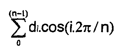
- Verfahren zur Erzeugung eines numerischen Werts Cg, der repräsentativ ist für das mittlere Gasmoment, das von jeder Verbrennung des Gasgemisches in den Zylindern einer Wärmekraftmaschine erzeugt wird, umfassend:Messmarkierungen (14, 16), die an einem Kranz (12) angeordnet sind, der fest mit dem Schwungrad des Motors oder seiner Kurbelwelle verbunden ist;Mittel (18, 20), um mindestens eine Referenz zur Indexierung der Markierungen zu definieren;einen Sensor (22) für das Vorbeilaufen der Markierungen (14, 16), der fix in der Nähe des Kranzes (12) montiert ist;wobei das Verfahren darin besteht:einen primären numerischen Wert di zu erzeugen (26, 30), der repräsentativ ist für die momentane Zeitspanne des Vorbeilaufens jeder Markierung (14, 16) vor dem Sensor (22);ausgehend von den primären numerischen Werten di einen ersten sekundären numerischen Wert T zu ermitteln (42), der repräsentativ ist für die Gesamtdauer des Vorbeilaufens vor dem Sensor (22) jeder Serie von n Markierungen, die das Winkelintervall der Verbrennungen im Motor definieren;einen zweiten sekundären numerischen Wert D zu ermitteln (46), der repräsentativ ist für die Projektion auf die Phasenreferenzlinie der Markierungen (18, 20), entsprechend dem Nullpunkt der Winkelperioden der Verbrennungen, der Amplitude der alternierenden Komponente der momentanen Zeitspannen di des Vorbeilaufens der Markierungen (14, 16) vor dem Sensor (22) bei der Frequenz der Verbrennungen im Motor;den gesuchten numerischen Wert Cg ausgehend von der Beziehung Cg = A.D/T3 + B/T2 zu ermitteln (54), wobei A und B (56) experimentell bestimmte Konstanten sind;wobei das Verfahren dadurch gekennzeichnet ist, dass es darüber hinaus darin besteht,einen Vermessungshorizont zu erstellen (36), der mindestens gleich ist dem Winkelintervall zwischen zwei aufeinanderfolgenden Explosionen im Motor;die momentanen Zeitspannen di des Vorbeilaufens der in diesem Vermessungshorizont enthaltenen Markierungen in eine relativ kleine Anzahl von Zeitspannen du0, ..., dun des Vorbeilaufens von Markierungspaketen zu gruppieren (36) und diese Zeitspannen du durch ihren Rang 0 ... n in jedem gerade analysierten Vermessungshorizont zu identifizieren;durch Addition und Subtraktion (46), eventuell gewichtet, eine gegebene Anzahl von Zeitspannen mit bestimmten Rängen miteinander zu kombinieren, um eine Größe Q zu erzeugen, die bei der Analysefrequenz der Explosionen des Motors einen Mittelwert von null und eine Frequenzcharakteristik von nicht null aufweist;eine solche Gewichtungskonstante p zu bestimmen, dass der Term D = p.Q, der durch eine vereinfachte Berechnung erzielt wird, zumindest für die Analysefrequenz und für die Kombination der Zeitspannen; die verwendet wurde, um Q auszudrücken, eine Frequenzcharakteristik aufweist, die annähernd identisch ist mit jener, die für folgenden Term erzielt wird:

- Verfahren gemäß Anspruch 1, dadurch gekennzeichnet, dassdie Zahl der Pakete, die in einem Vermessungshorizont enthalten sind, eine gerade Zahl ist;die Winkellängen dieser Pakete gleich sind;die Zahl der Zeitspannen von Paketen, die kombiniert werden, um Q zu erzeugen, eine gerade Zahl von mindestens gleich vier ist.
- Verfahren nach Anspruch 1 oder 2, dadurch gekennzeichnet, dass die Frequenzcharakteristik des Terms D = p.Q bis zu vier Mal die Analysefrequenz annähernd identisch mit der ursprünglich erhaltenen ist.
- Verfahren nach einem der vorhergehenden Ansprüche, dadurch gekennzeichnet, dass der Vermessungshorizont außer dem Winkelintervall, das zwei aufeinanderfolgende Explosionen im Motor trennt, eine kleine Zahl von Markierungen umfasst, die zu beiden Seiten dieses Intervalls angeordnet sind.
- Verfahren nach einem der Ansprüche 1, 3, 4, dadurch gekennzeichnet, dass die Markierungspakete eines Vermessungshorizonts nicht von exakt identischen Längen sind.
- Verfahren nach den Ansprüchen 1 und 2, dadurch gekennzeichnet, dassder Vermessungshorizont exakt definiert wird durch das Winkelintervall, das zwei Explosionen im Motor trennt;die Anzahl der Markierungspakete sechs ist und die sechs gemessenen Zeitspannen mit du0, ..., du5 bezeichnet werden;die Größe Q = (du0 - du2 - du3 + du5) und die Gewichtungskonstante p = π/2
- Verfahren nach Anspruch 1, dadurch gekennzeichnet, dass:das Intervall zwischen zwei aufeinanderfolgenden Explosionen in sechs Pakete von identischer Winkellänge unterteilt ist;der Vermessungshorizont gleich sieben aufeinanderfolgenden Paketen ist, die mit du0, ..., du6 bezeichnet werden;für die Größe Q gilt: Q = du0 - du3 + 3/2.(du6 - du4).
- Verfahren zur Erzeugung eines ersten numerischen Werts Cg, der repräsentativ ist für das mittlere Gasmoment, das durch jede Verbrennung des Gasgemisches in den Zylindem einer Wärmekraftmaschine erzeugt wird, nach einem der Ansprüche 1 bis 7, und eines zweiten numerischen Werts δCg, der repräsentativ ist für die Schwankungen des auf einen Motor mit zwei oder vier Zylindern einwirkenden Widerstandsmoments, wobei das Verfahren zur Erzeugung des zweiten Werts δCg dadurch gekennzeichnet ist, dass es darin besteht:einen Vermessungshorizont zu erstellen (36), der mindestens gleich ist dem Winkelintervall zwischen zwei aufeinanderfolgenden Explosionen im Motor;die momentanen Zeitspannen di des Vorbeilaufens der in diesem Vermessungshorizont enthaltenen Markierungen in eine relativ kleine Anzahl von Zeitspannen du0, ..., dun' des Vorbeilaufens von Markierungspaketen zu gruppieren (36) und diese Zeitspannen du durch ihren Rang 0 ... n' in jedem gerade analysierten Vermessungshorizont zu identifizieren, wobei die Winkelwerte der Pakete der Zeitspannen mit den Rängen 0 und n' gleich sind;der Zeitspanne des letzten Markierungspakets des letzten, vorher analysierten Vermessungshorizonts das Bezugszeichen du-1 und der Zeitspanne des ersten Markierungspakets des nächsten analysierten Vermessungshorizonts das Bezugszeichen du+1 zuzuweisen (38-40);vier dieser Zeitspannen du gemäß einer Beziehung q = (du0 - du-1 + dun' - du+1) zu kombinieren (47);den gesuchten Term δCg gemäß der Beziehung δCg = a.q.A/T3 zu ermitteln (55), wobei a eine neue Konstante ist, die vom Winkelwert der vier betroffenen Markierungspakete abhängt.
- Verfahren nach Anspruch 8, dadurch gekennzeichnet, dass:der Vermessungshorizont exakt definiert wird durch das Winkelintervall, das zwei Explosionen im Motor trennt;die Zahl der Markierungspakete im Vermessungshorizont sechs ist und der Winkelwert jedes Pakets π/6 ist;die Konstante a = π/2
- Verfahren nach Anspruch 8, dadurch gekennzeichnet, dass, da das Winkelintervall der Markierungspakete mit den Zeitspannen, die mit du0 und dun' bezeichnet werden, relativ groß ist, um einen genaueren Term δCg zu erzeugen, die Vermessungshorizonte eine leichte Phasenvorverschiebung gegenüber den Intervallen der oberen Totpunkte des Motors aufweisen.
- Verfahren nach den Ansprüchen 6 und 8, dadurch gekennzeichnet, dass zur Erzeugung eines Terms Q, der um die niederfrequenten Störungen berichtigt ist, die durch die Schwankungen des Widerstandsmoments erzeugt werden, das auf den Motor einwirkt, dieser Term gemäß folgender Beziehung berechnet (50) wird:
- Verfahren zur Erzeugung eines numerischen Werts Cgc, der repräsentativ ist für das mittlere Gasmoment, das durch jede Verbrennung des Gasgemisches in den vier Zylindern einer Wärmekraftmaschine erzeugt wird, gemäß einem der Ansprüche 1 bis 11, und berichtigt um die Einflüsse der besonderen Bedingungen dieser Verbrennungen, wobei das Verfahren dadurch gekennzeichnet ist, dass es auch darin besteht:insbesondere im Luftansaugkrümmer des Motors die physikalischen Parameter zu messen (58 - 60 - 70), die es ermöglichen, die Luftmasse M (64 - 74), die im Lauf der Verbrennungsperiode eines anderen Zylinders in einen Zylinder gepumpt wird, sowie das zu diesem Zweck erforderliche Pumpmoment Cp (64 - 78) zu bestimmen;die Werte dieser physikalischen Parameter oder jene der Größen M und Cp während der zwei folgenden Verbrennungsperioden zu speichern (62 - 72);die auf diese Weise gespeicherten Daten zu kombinieren (68 - 86), um einen Term Hn' zur Korrektur des Moments Cgn' zu erzeugen, das zur Verbrennungsperiode des Rangs n gehört, und zwar gemäß der Beziehung Hn' = -δ.(Mn'-2 + Mn'-1) + α.Cp(n'-2), wobei δ und α vom Motortyp abhängende Konstanten sind;das korrigierte mittlere Gasmoment zu berechnen (68), das im Lauf der Verbrennungsperiode des Rangs n erzeugt wird, und zwar gemäß der Beziehung Cgcn' = h,Cgn' + Hn', wobei h eine vom Motortyp abhängende Eichkonstante ist.
- Verfahren nach Anspruch 12, dadurch gekennzeichnet, dass:die Bestimmung der Luftmasse M darin besteht, den Druck Pc im Luftansaugkrümmer des Motors zu messen (60) und M gemäß der Beziehung M = Pc.RN zu berechnen (64), wobei RN der Füllungsgrad der Zylinder des Motors ist, der in Abhängigkeit von der Geschwindigkeit N des Motors annähernd konstant ist;die Bestimmung des Pumpmoments Cp darin besteht, den Luftdruck Pa zu messen (58) und Cp gemäß der Beziehung Cp = (Pc - Pa) zu berechnen (64).
- Verfahren nach Anspruch 12, dadurch gekennzeichnet, dass:die Bestimmung der Luftmasse M darin besteht, den Massendurchsatz Da der Luft im Krümmer zu messen (70) und M gemäß der Beziehung M = Da.T zu berechnen (74), wobei T die Periode der Verbrennungen ist;die Bestimmung des Pumpmoments Cp dann besteht, Cp gemäß der Beziehung Cp = (Da.T - M0) zu berechnen (78), wobei M0 die Luftmasse ist, die in einen Zylinder bei voll geöffneter Drosselklappe eingeführt wird.
- Verfahren nach einem der Ansprüche 12, 13, 14, dadurch gekennzeichnet, dass der Term D der Beziehung, die Cg definiert, durch die Anwendung folgender Schritte erzielt wird:einen Vermessungshorizont erstellen, der mindestens gleich ist dem Winkelintervall zwischen zwei aufeinanderfolgenden Explosionen im Motor, und diesen Vermessungshorizont in eine relativ kleine Anzahl von Markierungspaketen teilen;die Zeitspannen des Vorbeilaufens jedes dieser Pakete vor dem Sensor (22) berechnen (36) und ihnen einen Rang in jedem Vermessungshorizont zuweisen;durch Addition und Subtraktion (46) eine gegebene Anzahl von Zeitspannen mit bestimmten Rängen miteinander kombinieren, so dass eine Größe Q erzeugt wird, die bei der Analysefrequenz der Explosionen des Motors einen Mittelwert von null und eine Frequenzcharakteristik von nicht null aufweist;eine solche Gewichtungskonstante p bestimmen, dass der Term D = p.Q, der durch eine vereinfachte Berechnung erzielt wird, zumindest für die Analysefrequenz und für die Kombination der Zeitspannen, die verwendet wurde, um Q auszudrücken, eine Frequenzcharakteristik aufweist, die annähernd identisch ist mit jener, die für folgenden Term erzielt wird:

- Verfahren nach Anspruch 15, dadurch gekennzeichnet, dass der Winkelwert jedes Markierungspaktes π/6 ist.
- Verfahren nach Anspruch 15, dadurch gekennzeichnet, dass zur Erzeugung eines Terms Dc = p.Qc, der um die niederfrequenten Störungen berichtigt ist, die auf den Motor einwirken, jedes Markierungspaket π/6 misst, die Konstante p gleich π/2
- Vorrichtung zur Erzeugung eines numerischen Werts Cg, der repräsentativ ist für das mittlere Gasmoment, das durch jede Verbrennung des Gasgemisches in den Zylindern einer Wärmekraftmaschine erzeugt wird, die mit niedriger Drehzahl betrieben wird,wobei der Motor umfasst:Messmarkierungen (14, 16), die an einem Kranz (12) angeordnet sind, der fest mit dem Schwungrad oder der Kurbelwelle verbunden ist;Mittel (18, 20), um mindestens eine Referenz zur Indexierung der Markierungen zu definieren;einen Sensor (22) für das Vorbeilaufen der Markierungen (14, 16), der fix in der Nähe des Kranzes (12) montiert ist;wobei die Vorrichtung umfasst:Rechenmittel (30), um einen primären numerischen Wert di zu erzeugen, der repräsentativ ist für die momentane Zeitspanne des Vorbeilaufens jeder Markierung (14, 16) vor dem Sensor (22);Rechenmittel (42), um ausgehend von den primären numerischen Werten di einen ersten sekundären numerischen Wert T zu ermitteln, der repräsentativ ist für die Gesamtdauer des Vorbeilaufens vor dem Sensor (22) jeder Serie von n Markierungen, die das Winkelintervall definiert, das zwei aufeinanderfolgende Verbrennungen im Motor trennt;Rechenmittel (46), um einen zweiten sekundären numerischen Wert D zu ermitteln, der repräsentativ ist für die Projektion auf die Phasenreferenzlinie der Markierungen (18, 20), entsprechend dem Nullpunkt der Winkelperioden der Verbrennungen, der Amplitude der alternierenden Komponente der momentanen Zeitspannen di des Vorbeilaufens der Markierungen (14, 16) vor dem Sensor (22) bei der Frequenz der Verbrennungen im Motor;Rechenmittel (54), um den gesuchten numerischen Wert Cg ausgehend von der Beziehung Cg = A.D/T3 + B/T2 zu ermitteln, wobei A und B experimentell bestimmte Konstanten sind, die in einem Speicher (56) enthalten sind;wobei die Vorrichtung dadurch gekennzeichnet ist, dass sie auch umfasst:Verarbeitungs- und Rechenmittel (36), um einen Vermessungshorizont zu erstellen, der mindestens gleich ist dem genannten Winkelintervall, um die momentanen Zeitspannen di des Vorbeilaufens der in diesem Vermessungshorizont enthaltenen Markierungen in eine relativ kleine Anzahl von Zeitspannen du0, ..., dun des Vorbeilaufens von Markierungspaketen zu gruppieren und um diese Zeitspannen du durch ihren Rang (0 ... n) in jedem Vermessungshorizont zu identifizieren;Rechenmittel (46), um durch Addition und Subtraktion eine gegebene Anzahl von Zeitspannen von Paketen mit bestimmten Rängen miteinander zu kombinieren, um eine Größe Q zu erzeugen, die bei der Analysefrequenz der Explosionen des Motors einen Mittelwert von null und eine Frequenzcharakteristik von nicht null aufweist;Rechenmittel (50), um einen Term D = p.Q ausgehend vom vorher berechneten Wert Q und von einem Gewichtungskoeffizienten p zu erzeugen, der experimentell bestimmt und in einem Speicher (52) gespeichert ist, wobei der Wert von p und die Kombination der Zeitspannen, die verwendet wurde, um Q auszudrücken, so bestimmt wurden, dass der Term D, der auf diese Weise durch eine vereinfachte Berechnung erzielt wird, zumindest für die Analysefrequenz eine Frequenzcharakteristik aufweist, die identisch ist mit jener, die für folgenden Term erzielt wird:
- Vorrichtung nach Anspruch 18 zur Erzeugung eines ersten numerischen Werts Cg, der repräsentativ ist für das mittlere Gasmoment, das durch jede Verbrennung des Gasgemisches in den Zylindern einer Wärmekraftmaschine erzeugt wird, die mit niedriger Drehzahl betrieben wird, und eines zweiten numerischen Werts δCg, der repräsentativ ist für die Schwankungen des auf einen derartigen Motor mit zwei oder vier Zylindern einwirkenden Widerstandsmoments, wobei die Vorrichtung zur Erzeugung des zweiten Werts δCg dadurch gekennzeichnet ist, dass sie auch umfasst:Verarbeitungs- und Rechenmittel (36), um einen Vermessungshorizont zu erstellen, der mindestens gleich ist dem Winkelintervall zwischen zwei aufeinanderfolgenden Explosionen im Motor, um die momentanen Zeitspannen di des Vorbeilaufens der in diesem Vermessungshorizont enthaltenen Markierungen in eine relativ kleine Anzahl von Zeitspannen du0, ..., dun' des Vorbeilaufens von Markierungspaketen zu gruppieren und um diese Zeitspannen du durch ihren Rang 0 ... n' in jedem gerade analysierten Vermessungshorizont zu identifizieren, wobei die Winkelwerte der Markierungspakete mit den Zeitspannen der Ränge 0 und n' gleich sind;Mittel (38) zum Speichern der Zeitspannen du0, ..., dun' sowie einerseits der Zeitspanne des letzten Markierungspakets des letzten, vorher analysierten Vermessungshorizonts, wobei diesem das Bezugszeichen du-1 zugewiesen wird, und andererseits der Zeitspanne des ersten Markierungspakets des nächsten analysierten Vermessungshorizonts, wobei diesem das Bezugszeichen du+1 zugewiesen wird;Mittel (47), um einen Term q gemäß der Beziehung q = (du0 - du-1 + dun' - du+1) zu kombinieren;Mittel (55), um den gesuchten Term δCg gemäß der Beziehung δCg = a.q.A/T3 zu ermitteln, wobei a eine neue Konstante ist, die vom Winkelwert der vier betroffenen Markierungspakete abhängt.
- Vorrichtung nach einem der Ansprüche 18 bis 19 zur Erzeugung eines numerischen Werts Cg, der repräsentativ ist für das mittlere Gasmoment, das durch jede Verbrennung des Gasgemisches in den Zylindern einer Wärmekraftmaschine mit vier Takten erzeugt wird, die mit niedriger Drehzahl betrieben wird, wobei der Wert um die Einflüsse der besonderen Bedingungen dieser Verbrennungen berichtigt ist, dadurch gekennzeichnet, dass sie auch umfasst:Mittel (60 - 62 - 64 oder 70 - 72 - 74), die Sensoren (60 - 70) einschließen, die im Luftansaugkrümmer installiert sind, um die Luftmasse M zu bestimmen, die im Lauf der Verbrennungsperiode eines anderen Zylinders in einen Zylinder gepumpt wird;Mittel (58 - 60 - 62 - 64 oder 70 - 72 - 78), um das zu diesem Zweck notwendige Pumpmoment Cp zu bestimmen;Mittel (62 oder 72-76-82), um die Daten M und Cp oder die konstituierenden Elemente dieser Daten während der beiden folgenden Verbrennungsperioden zu speichern;Mittel (64 oder 86), um diese Daten oder deren konstituierende Elemente zu kombinieren, um einen Term Hn' zur Korrektur des Moments Cgn' zu erzeugen, das zur Verbrennungsperiode des Rangs n' gehört, und zwar gemäß der Beziehung:
Hn' = -δ.(Mn'-2 + Mn'-1) + α.Cp(n'-2), wobei δ und α vom Motortyp abhängende Konstantensind;Rechenmittel (68), um das korrigierte mittlere Gasmoment zu berechnen, das im Lauf der Verbrennungsperiode des Rangs n' erzeugt wurde, und zwar gemäß der Beziehung:
Cgcn' = h.Cgn' + Hn', wobei h eine vom Motortyp abhängende Eichkonstante ist,wobei die Konstanten δ, α und h in einem Permanentspeicher (66 oder 84) gespeichert sind.
Applications Claiming Priority (5)
| Application Number | Priority Date | Filing Date | Title |
|---|---|---|---|
| FR9506780A FR2735232B1 (fr) | 1995-06-08 | 1995-06-08 | Procede et dispositif de mesure du couple d'un moteur thermique a combustion interne |
| FR9506780 | 1995-06-08 | ||
| FR9506781 | 1995-06-08 | ||
| FR9506781A FR2735233B1 (fr) | 1995-06-08 | 1995-06-08 | Procede et dispositif de mesure du couple d'un moteur thermique a combustion interne prenant en compte les conditions particulieres de combustion |
| PCT/FR1996/000864 WO1996042002A1 (fr) | 1995-06-08 | 1996-06-07 | Procede et dispositif de mesure du couple d'un moteur thermique a combustion interne |
Publications (2)
| Publication Number | Publication Date |
|---|---|
| EP0775302A1 EP0775302A1 (de) | 1997-05-28 |
| EP0775302B1 true EP0775302B1 (de) | 2002-12-18 |
Family
ID=26232014
Family Applications (1)
| Application Number | Title | Priority Date | Filing Date |
|---|---|---|---|
| EP96922077A Expired - Lifetime EP0775302B1 (de) | 1995-06-08 | 1996-06-07 | Verfahren und vorrichtung zum messen des drehmomentes eines thermischen internen verbrennungsmotors |
Country Status (5)
| Country | Link |
|---|---|
| US (1) | US5771483A (de) |
| EP (1) | EP0775302B1 (de) |
| JP (1) | JP3672316B2 (de) |
| DE (1) | DE69625451T2 (de) |
| WO (1) | WO1996042002A1 (de) |
Families Citing this family (13)
| Publication number | Priority date | Publication date | Assignee | Title |
|---|---|---|---|---|
| DE19725233B4 (de) * | 1997-06-14 | 2005-03-24 | Volkswagen Ag | Verfahren zur Anpassung der Einspritzmenge einer Brennkraftmaschine zur Laufruheregelung |
| JP2003512603A (ja) * | 1999-10-05 | 2003-04-02 | テクノロジィ ファイナンス コーポレイション(プロプライエタリー) リミテッド | 回転軸におけるトルクによるねじれの測定 |
| US6336070B1 (en) * | 2000-03-01 | 2002-01-01 | Ford Global Technologies, Inc. | Apparatus and method for engine crankshaft torque ripple control in a hybrid electric vehicle |
| SE521998C2 (sv) * | 2001-06-13 | 2004-01-07 | Abb Ab | Metod för att bestämma övre dödpunkten i en förbränningsmotor |
| JP4220454B2 (ja) * | 2004-10-14 | 2009-02-04 | 本田技研工業株式会社 | エンジンの仕事量を算出する装置 |
| US7047125B1 (en) | 2005-02-25 | 2006-05-16 | Caterpillar Inc. | Internal combustion engine performance calibration systems |
| DE102006061579A1 (de) * | 2006-12-27 | 2008-07-03 | Robert Bosch Gmbh | Verfahren zur Bestimmung eines Drehzahlwertes |
| RU174174U1 (ru) * | 2017-01-31 | 2017-10-05 | Федеральное государственное казенное военное образовательное учреждение высшего образования "ВОЕННАЯ АКАДЕМИЯ МАТЕРИАЛЬНО-ТЕХНИЧЕСКОГО ОБЕСПЕЧЕНИЯ имени генерала армии А.В. Хрулева" | Автоматизированная система контроля данных о техническом состоянии двигателя внутреннего сгорания транспортного средства |
| WO2019069211A1 (en) * | 2017-10-04 | 2019-04-11 | The Board Of Trustees Of Western Michigan University | TORQUE SENSOR FOR MOTORS |
| FR3087495A1 (fr) | 2018-10-22 | 2020-04-24 | Continental Automotive France | Procede et systeme de controle d'un regime moteur de vehicule |
| RU2743092C9 (ru) * | 2019-06-17 | 2022-02-22 | федеральное государственное бюджетное образовательное учреждение высшего образования "Ульяновский государственный университет" | Способ и система контроля параметров технического состояния двигателя внутреннего сгорания |
| RU2755757C1 (ru) * | 2020-11-03 | 2021-09-21 | Федеральное государственное бюджетное образовательное учреждение высшего образования "Санкт-Петербургский государственный архитектурно-строительный университет" | Автоматизированная система контроля экологических параметров транспортных средств |
| CN113818963B (zh) * | 2021-09-23 | 2022-10-14 | 宁波吉利罗佑发动机零部件有限公司 | 发动机扭矩的预测方法、装置及计算机存储介质 |
Family Cites Families (14)
| Publication number | Priority date | Publication date | Assignee | Title |
|---|---|---|---|---|
| JPS5146201B2 (de) * | 1972-05-26 | 1976-12-08 | ||
| US5487008A (en) * | 1990-04-20 | 1996-01-23 | The Regents Of The University Of Michigan | Method and system for detecting the misfire of a reciprocating internal combustion engine in frequency domain |
| JPH0752129B2 (ja) * | 1990-05-22 | 1995-06-05 | 株式会社ユニシアジェックス | エンジン出力表示計 |
| EP0463537B1 (de) * | 1990-06-29 | 1997-07-16 | Günter Dr.-Ing. Nobis | Verfahren zur prüfstandslosen Ermittlung technischer Kennwerte von Verbrennungsmotoren und deren Einzelzylindern und Vorrichtung zum Durchführen dieses Verfahrens |
| JP2564427B2 (ja) * | 1991-01-14 | 1996-12-18 | 三菱電機株式会社 | 内燃機関失火検出方法及び装置 |
| FR2681425B1 (fr) * | 1991-09-12 | 1993-11-26 | Renault Regie Nale Usines | Procede et dispositif de mesure du couple d'un moteur thermique a combustion interne. |
| US5241855A (en) * | 1991-10-31 | 1993-09-07 | Ford Motor Company | Method and apparatus for inferring engine torque |
| US5396427A (en) * | 1992-03-09 | 1995-03-07 | Snap-On Incorporated | Method and apparatus for determining relative contributions of individual cylinders of internal combustion engine |
| FR2689934B1 (fr) * | 1992-04-10 | 1994-06-17 | Siemens Automotive Sa | Procede et dispositif de detection des irregularites de combustion d'un moteur en particulier a moyen et haut regimes, application a un systeme de controle d'un moteur a injection. |
| DE4407167C2 (de) * | 1994-03-04 | 1997-08-28 | Daimler Benz Ag | Verfahren zur Bestimmung von Betriebsparametern einer Brennkraftmaschine durch Auswerten der Drehzahlinformation |
| JPH07259631A (ja) * | 1994-03-18 | 1995-10-09 | Mitsubishi Electric Corp | 内燃機関の失火検出装置 |
| JP3327003B2 (ja) * | 1994-11-07 | 2002-09-24 | 三菱電機株式会社 | 内燃機関の気筒識別装置 |
| JP3323974B2 (ja) * | 1995-02-24 | 2002-09-09 | 株式会社ユニシアジェックス | 内燃機関の制御装置 |
| US5663493A (en) * | 1996-05-17 | 1997-09-02 | Fluke Corporation | Apparatus and method for measuring relative compression |
-
1996
- 1996-06-07 EP EP96922077A patent/EP0775302B1/de not_active Expired - Lifetime
- 1996-06-07 DE DE69625451T patent/DE69625451T2/de not_active Expired - Lifetime
- 1996-06-07 US US08/776,587 patent/US5771483A/en not_active Expired - Lifetime
- 1996-06-07 JP JP50269497A patent/JP3672316B2/ja not_active Expired - Fee Related
- 1996-06-07 WO PCT/FR1996/000864 patent/WO1996042002A1/fr not_active Ceased
Also Published As
| Publication number | Publication date |
|---|---|
| JPH10504110A (ja) | 1998-04-14 |
| DE69625451D1 (de) | 2003-01-30 |
| US5771483A (en) | 1998-06-23 |
| DE69625451T2 (de) | 2004-03-11 |
| JP3672316B2 (ja) | 2005-07-20 |
| EP0775302A1 (de) | 1997-05-28 |
| WO1996042002A1 (fr) | 1996-12-27 |
Similar Documents
| Publication | Publication Date | Title |
|---|---|---|
| EP0532419B1 (de) | Verfahren und Vorrichtung zur Drehmomentmessung von Wärmemotoren mit interner Verbrennung | |
| EP0775302B1 (de) | Verfahren und vorrichtung zum messen des drehmomentes eines thermischen internen verbrennungsmotors | |
| EP0532420B1 (de) | Verfahren und Vorrichtung zum Messen des Drehmomentes eines thermischen internen Verbrennungsmotors, insbesondere bei Berücksichtigung der Rückführung des Auspuffgases und des zurückbleibenden verbrannten Gases und des Verbrennungsmittelüberschusses | |
| JP3463476B2 (ja) | 多気筒内燃機関の失火検出装置 | |
| CN102589888B (zh) | 发动机负荷检测装置以及发动机负荷检测方法 | |
| EP0894254B1 (de) | Verfahren zur bestimmung des drehmomentes eines verbrennungsmotors | |
| EP0102273B1 (de) | Zünd- und Einspritzungssteueranlage für eine Brennkraftmaschine | |
| EP1052488B1 (de) | Verfahren und Vorrichtung zur Messung des Drehmomentes einer Brennkraftmaschine | |
| EP0774110B1 (de) | Verfahren und vorrichtung zum erkennen von verbrennungsaussetzern einer brennkraftmaschine mit funkenzündung | |
| EP0522908B1 (de) | Verfahren und System um die Luftmenge in einem Zylinder einer Brennkraftmaschine zuzurechnen | |
| WO2008080861A1 (fr) | Procede d'estimation du couple d'un moteur a combustion interne | |
| FR2937684A1 (fr) | Procede de determination de la duree d'une dent longue d'une cible montee sur un vilebrequin de moteur a combustion interne | |
| EP0029374B1 (de) | Signal-generator zur Korrektur der Einstellung der Frühzündung in Abhängigkeit vom Klopfverhalten | |
| FR2757945A1 (fr) | Procede de calcul du couple d'un moteur thermique a injection commandee electroniquement | |
| FR2735233A1 (fr) | Procede et dispositif de mesure du couple d'un moteur thermique a combustion interne prenant en compte les conditions particulieres de combustion | |
| FR2735232A1 (fr) | Procede et dispositif de mesure du couple d'un moteur thermique a combustion interne | |
| EP0695865B1 (de) | Verfahren zur Korrektur der Unsymmetrien eines Geberrades | |
| EP1952004B1 (de) | Verfahren zur schätzung der pro zyklus im zylinder einer brennkraftmaschine eingeschlossenen gasmasse | |
| EP1217354B1 (de) | Verfahren zur Auswertung des Drehmomentes eines Brennkraftmotors | |
| EP0932751B1 (de) | Synchronisationsverfahren für das elektronische regelsystem einer brennkraftmaschine | |
| FR2797950A1 (fr) | Procede pour determiner le couple reel par un moteur a combustion interne | |
| FR2950655A1 (fr) | Procede d'evaluation des couples instantanes des cylindres d'un moteur a combustion interne. | |
| JP3304373B2 (ja) | エンジンの失火検出装置 |
Legal Events
| Date | Code | Title | Description |
|---|---|---|---|
| PUAI | Public reference made under article 153(3) epc to a published international application that has entered the european phase |
Free format text: ORIGINAL CODE: 0009012 |
|
| 17P | Request for examination filed |
Effective date: 19970211 |
|
| AK | Designated contracting states |
Kind code of ref document: A1 Designated state(s): DE ES FR GB IT |
|
| 17Q | First examination report despatched |
Effective date: 19991015 |
|
| GRAG | Despatch of communication of intention to grant |
Free format text: ORIGINAL CODE: EPIDOS AGRA |
|
| GRAG | Despatch of communication of intention to grant |
Free format text: ORIGINAL CODE: EPIDOS AGRA |
|
| GRAH | Despatch of communication of intention to grant a patent |
Free format text: ORIGINAL CODE: EPIDOS IGRA |
|
| GRAG | Despatch of communication of intention to grant |
Free format text: ORIGINAL CODE: EPIDOS AGRA |
|
| GRAH | Despatch of communication of intention to grant a patent |
Free format text: ORIGINAL CODE: EPIDOS IGRA |
|
| GRAH | Despatch of communication of intention to grant a patent |
Free format text: ORIGINAL CODE: EPIDOS IGRA |
|
| RAP1 | Party data changed (applicant data changed or rights of an application transferred) |
Owner name: RENAULT S.A.S. |
|
| GRAH | Despatch of communication of intention to grant a patent |
Free format text: ORIGINAL CODE: EPIDOS IGRA |
|
| GRAA | (expected) grant |
Free format text: ORIGINAL CODE: 0009210 |
|
| AK | Designated contracting states |
Kind code of ref document: B1 Designated state(s): DE ES FR GB IT |
|
| PG25 | Lapsed in a contracting state [announced via postgrant information from national office to epo] |
Ref country code: IT Free format text: LAPSE BECAUSE OF FAILURE TO SUBMIT A TRANSLATION OF THE DESCRIPTION OR TO PAY THE FEE WITHIN THE PRESCRIBED TIME-LIMIT;WARNING: LAPSES OF ITALIAN PATENTS WITH EFFECTIVE DATE BEFORE 2007 MAY HAVE OCCURRED AT ANY TIME BEFORE 2007. THE CORRECT EFFECTIVE DATE MAY BE DIFFERENT FROM THE ONE RECORDED. Effective date: 20021218 Ref country code: GB Free format text: LAPSE BECAUSE OF FAILURE TO SUBMIT A TRANSLATION OF THE DESCRIPTION OR TO PAY THE FEE WITHIN THE PRESCRIBED TIME-LIMIT Effective date: 20021218 |
|
| REG | Reference to a national code |
Ref country code: GB Ref legal event code: FG4D Free format text: NOT ENGLISH |
|
| REF | Corresponds to: |
Ref document number: 69625451 Country of ref document: DE Date of ref document: 20030130 Kind code of ref document: P Ref document number: 69625451 Country of ref document: DE Date of ref document: 20030130 |
|
| GBV | Gb: ep patent (uk) treated as always having been void in accordance with gb section 77(7)/1977 [no translation filed] |
Effective date: 20021218 |
|
| PG25 | Lapsed in a contracting state [announced via postgrant information from national office to epo] |
Ref country code: ES Free format text: LAPSE BECAUSE OF FAILURE TO SUBMIT A TRANSLATION OF THE DESCRIPTION OR TO PAY THE FEE WITHIN THE PRESCRIBED TIME-LIMIT Effective date: 20030627 |
|
| PLBE | No opposition filed within time limit |
Free format text: ORIGINAL CODE: 0009261 |
|
| STAA | Information on the status of an ep patent application or granted ep patent |
Free format text: STATUS: NO OPPOSITION FILED WITHIN TIME LIMIT |
|
| 26N | No opposition filed |
Effective date: 20030919 |
|
| PG25 | Lapsed in a contracting state [announced via postgrant information from national office to epo] |
Ref country code: FR Free format text: LAPSE BECAUSE OF NON-PAYMENT OF DUE FEES Effective date: 20040227 |
|
| REG | Reference to a national code |
Ref country code: FR Ref legal event code: ST |
|
| PGFP | Annual fee paid to national office [announced via postgrant information from national office to epo] |
Ref country code: DE Payment date: 20140619 Year of fee payment: 19 |
|
| REG | Reference to a national code |
Ref country code: DE Ref legal event code: R119 Ref document number: 69625451 Country of ref document: DE |
|
| PG25 | Lapsed in a contracting state [announced via postgrant information from national office to epo] |
Ref country code: DE Free format text: LAPSE BECAUSE OF FAILURE TO SUBMIT A TRANSLATION OF THE DESCRIPTION OR TO PAY THE FEE WITHIN THE PRESCRIBED TIME-LIMIT Effective date: 20160101 |