EP0775463A2 - Geschirrspülmaschine und deren Steuerung - Google Patents
Geschirrspülmaschine und deren Steuerung Download PDFInfo
- Publication number
- EP0775463A2 EP0775463A2 EP96308335A EP96308335A EP0775463A2 EP 0775463 A2 EP0775463 A2 EP 0775463A2 EP 96308335 A EP96308335 A EP 96308335A EP 96308335 A EP96308335 A EP 96308335A EP 0775463 A2 EP0775463 A2 EP 0775463A2
- Authority
- EP
- European Patent Office
- Prior art keywords
- load
- relay
- motor
- loads
- appliance according
- Prior art date
- Legal status (The legal status is an assumption and is not a legal conclusion. Google has not performed a legal analysis and makes no representation as to the accuracy of the status listed.)
- Granted
Links
Images

Classifications
-
- A—HUMAN NECESSITIES
- A47—FURNITURE; DOMESTIC ARTICLES OR APPLIANCES; COFFEE MILLS; SPICE MILLS; SUCTION CLEANERS IN GENERAL
- A47L—DOMESTIC WASHING OR CLEANING; SUCTION CLEANERS IN GENERAL
- A47L15/00—Washing or rinsing machines for crockery or tableware
- A47L15/0018—Controlling processes, i.e. processes to control the operation of the machine characterised by the purpose or target of the control
- A47L15/0049—Detection or prevention of malfunction, including accident prevention
-
- A—HUMAN NECESSITIES
- A47—FURNITURE; DOMESTIC ARTICLES OR APPLIANCES; COFFEE MILLS; SPICE MILLS; SUCTION CLEANERS IN GENERAL
- A47L—DOMESTIC WASHING OR CLEANING; SUCTION CLEANERS IN GENERAL
- A47L15/00—Washing or rinsing machines for crockery or tableware
- A47L15/42—Details
- A47L15/46—Devices for the automatic control of the different phases of cleaning ; Controlling devices
-
- A—HUMAN NECESSITIES
- A47—FURNITURE; DOMESTIC ARTICLES OR APPLIANCES; COFFEE MILLS; SPICE MILLS; SUCTION CLEANERS IN GENERAL
- A47L—DOMESTIC WASHING OR CLEANING; SUCTION CLEANERS IN GENERAL
- A47L15/00—Washing or rinsing machines for crockery or tableware
- A47L15/42—Details
- A47L15/4293—Arrangements for programme selection, e.g. control panels; Indication of the selected programme, programme progress or other parameters of the programme, e.g. by using display panels
-
- A—HUMAN NECESSITIES
- A47—FURNITURE; DOMESTIC ARTICLES OR APPLIANCES; COFFEE MILLS; SPICE MILLS; SUCTION CLEANERS IN GENERAL
- A47L—DOMESTIC WASHING OR CLEANING; SUCTION CLEANERS IN GENERAL
- A47L2301/00—Manual input in controlling methods of washing or rinsing machines for crockery or tableware, i.e. information entered by a user
-
- A—HUMAN NECESSITIES
- A47—FURNITURE; DOMESTIC ARTICLES OR APPLIANCES; COFFEE MILLS; SPICE MILLS; SUCTION CLEANERS IN GENERAL
- A47L—DOMESTIC WASHING OR CLEANING; SUCTION CLEANERS IN GENERAL
- A47L2501/00—Output in controlling method of washing or rinsing machines for crockery or tableware, i.e. quantities or components controlled, or actions performed by the controlling device executing the controlling method
- A47L2501/05—Drain or recirculation pump, e.g. regulation of the pump rotational speed or flow direction
-
- A—HUMAN NECESSITIES
- A47—FURNITURE; DOMESTIC ARTICLES OR APPLIANCES; COFFEE MILLS; SPICE MILLS; SUCTION CLEANERS IN GENERAL
- A47L—DOMESTIC WASHING OR CLEANING; SUCTION CLEANERS IN GENERAL
- A47L2501/00—Output in controlling method of washing or rinsing machines for crockery or tableware, i.e. quantities or components controlled, or actions performed by the controlling device executing the controlling method
- A47L2501/06—Water heaters
Definitions
- the invention relates to a dishwasher and a control therefor, and, more specifically to a dishwasher and a control that shuts off power to failed electrical load circuits when power is not supplied to the motor, preventing the electrical load from continuing to operate for the entire operation ofthe dishwasher.
- Dishwashers commonly have a control that permits the user to select from various wash cycles and to select options for the various cycles.
- the dishwasher control receives the user inputs and controls the operation of the various components of the dishwasher, such as the pump, heater, detergent dispenser, etc. These components represent the electrical loads of the control.
- the circuit providing power to the loads have a main relay that controls the supply of power to the loads.
- the loads are normally switched so that they can be turned on and off as required.
- One problem with this type of control is that if one of the switches of the loads fails and the load circuit is left closed, then the load will continue to operate for the entire wash cycle because the main relay is closed for the entire wash cycle.
- the invention solves the problem of the prior dishwasher controls in a unique way which has the additional advantage of reducing the number elements needed in the control and thus reducing the cost of the control.
- the invention is a dishwasher and a control therefor.
- the dishwasher comprises at least a first electrical load and a second electrical load, which are connected in parallel.
- the first and second loads are energized by a power source having a first and second supply lines.
- a relay having contacts connects the first electrical load and the second electrical load in series to the first supply line.
- a solid state device connects the second electrical load in series to the second supply line.
- the first load is connected directly to the second supply line whereby if the solid state device fails in the closed position, power to the second load can be controlled by opening and closing the relay contacts.
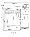
- FIG. 1 is a perspective view of a front loading dishwasher having circuit operation provided in accordance with the principles of the invention.
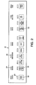
- FIG. 2 is a switch module for a dishwasher.
- FIG. 3 is a schematic diagram of a dishwasher and a control operating in accordance with the principles of the invention.
- a typical dishwasher 10 comprises a cabinet 12 housing a washing chamber (not shown) retained beneath a countertop 14.
- the dishwasher 10 has a control console 16 which houses a switch module 18, exposed to the user, and a control module 20, enclosed inside control console 16.
- dishwasher 10 There are racks upon which dishes and utensils are placed. There is at least one spray arm for spraying water throughout the washing chamber. There is a motor driven pump, that together with suitable valves, actuators, a heater and necessary sensors, cooperate to carry out a number of different automatic cycles preprogrammed in a control device, which, in the preferred embodiment, comprises a microcomputer.
- a control device which, in the preferred embodiment, comprises a microcomputer.
- Switch module 18 is shown enlarged in FIG. 2. It provides a number of switches 22 to enable a user to select dishwasher cycles and options, and display indicators 24 to display to the user information on the selections chosen and current status of the dishwasher.
- the switches 22, in combination, identify any one of a number of different automatic cycles within which the dishwasher is programmed to operate.
- automatic cycles such as POTS N PANS, HEAVY, NORMAL, LOW ENERGY, CHINA CRYSTAL, AND RINSE WASH LATER are typical.
- Operable within each automatic cycle, and selected by the user at 18, is an array of options. Examples of options which in practice are available in conventional dishwashers are DELAY START, AIR DRY, LOW ENERGY RINSE, HIGH TEMP WASH, and CANCEL DRAIN.
- FIG. 3 schematically illustrates the dishwasher control 25 according to the invention and is connected to the switch module 18 and a power source identified by lines L1 and L2.
- the control 25 receives input from the switch module 18 to control the operation of the dishwasher 10.
- the dishwasher control 25 will first be described conceptually by its functional components.
- the control 25 comprises a relay portion 25a, load portion 25b, a switch portion 25c, and a processor 26.
- the relay portion 25a connects the load portion 25b in series to line L1 of the power source.
- the switch portion 25c is in series with and connects the load portion 25b to line L2 of the power source.
- the processor 26 is connected to the switch module 18 and the relay portion 25a and the switch portion 25c and controls the energizing of the relay portion 25a and the switch portion 25c in response to programming that is responsive to inputs received from the switch module 18.
- the relay portion 25a control the flow of power to the load portion 25b and the switch portion 25c controls the actuation of the loads as directed by the processor 26.
- control 25 comprises a control module 20, which is a circuit board disposed in control console 16.
- the control module 20 includes the relay portion 25a, switch portion 25c and the processor 26.
- the load portion comprises typical electrical loads for a dishwasher and these loads are connected to the control module by a wiring harness in the typical manner known to one of skill in the art.
- the load portion 25b contains multiple parallel loads, one of which is an electric motor 36.
- the electric motor 36 further comprises a main winding 56, a drain winding 58, and a wash winding 60.
- Other illustrated loads include a detergent actuator 68, a wetting agent actuator 72, and a fill solenoid 76.
- the relay portion 25a comprises a heater relay 44 and a motor relay 46 which have respective contacts 28, and 30, which are controlled by the processor.
- the processor in the preferred embodiment is a microcomputer 26.
- the switch portion 25c comprises multiple semiconductor switches 64, 66, 70, 74, and 78.
- the main winding 56 of motor 36 is directly connected to line L2.
- the advantage of the invention is that the load connected to a failed, shorted semiconductor switch is turned off when the motor is not energized and is not left running during the entire operation of the dishwasher, like prior controls, and one less relay is required, reducing the number of components and cost of the control.
- Microcomputer 26 connects the electrical loads to the power ofL1 through the contacts of two electromechanical relays, heater relay contacts 28 and motor relay contacts 30.
- Heater relay contacts 28 are in series with heater element 32 which is also connected to L2.
- Motor relay contacts 30 are in series with load portion 25b (electrical loads that are connected in parallel, including the motor 36 and other loads to be energized while the motor 36 is running).
- One ofthe loads of load portion 25b is connected through sense resistor 38 to L2.
- the remaining loads of load portion 25b are each connected to L2 through one of the semiconductor switches, which are illustrated as triacs in the drawings, of switch group 25c. Each switch of group 25c is selectively controlled by Microcomputer 26.
- Microcomputer 26 located in control module 20 of FIG. 2, receives as inputs user selections entered manually by the user at switches 22 on the switch module 18, and sends as outputs to the display indicators 24 on switch module 18 information on the cycle and option selection as well as the current status ofthe dishwasher 10.
- the information received by the microcomputer 26 from the switch module 18 is typically in the form of digital signals developed as a function of the status of the switches 22 involved.
- supply leads L1 and L2 are connected respectively through a first door switch 40 and a second door switch 42 to the circuits of dishwasher 10. Further, the heater relay contacts 28 of heater relay 44 are connected through the hi-limit thermostat 92 to the heater element 32. The motor relay contacts 30 of motor relay 46 are connected to the wiring node 48.
- the operating thermostat 50 connects the wiring node 44 to the stat input 52 of microcomputer 26.
- the thermal protector 54 connects the main winding 56, the drain winding 58, and the wash winding 60, all components of the motor 54, to the wiring node 48.
- the main winding 56 also connects to the sense input 62 of microcomputer 26 and the sense resistor 38.
- the drain winding 58 also connects to the drain triac 64.
- the wash winding 60 also connects to the wash triac 66.
- the detergent actuator 68 is connected between the detergent triac 70 and the wiring node 48.
- the wetting agent actuator 72 is connected between wetting agent triac 74 and the wiring node 48.
- the fill solenoid 76 is connected to fill triac 78 and to wiring node 48 through overfill switch 80.
- the microcomputer outputs drain 82, wash 84, detergent 86, wetting agent 88, and fill 90 are all connected to the gate of the triac driving that respective load.
- Heat is provided when microcomputer 26 energizes the heater relay 44 that applies power through the heater relay contacts 28 and the hi-limit thermostat 92 to the heater element 32.
- the microcomputer 26 energizes the motor relay 46, closing motor relay contacts 30 to apply power to the wiring node 48 which includes one end of load portion 25b.
- Microcomputer 26 must also energize the appropriate triac (semiconductor switch) turning the triac on, connecting the selected load to L2. This means that triacs (64, 66, 70, 74 and 78) are not subject to electrical line transients when the motor relay contacts 30 are open; and, any load driven by a failed shorted triac will be turned off when the motor relay contacts 30 are opened.
- microcomputer 26 initiates a starting sequence for the motor 36.
- Microcomputer 26 energizes motor relay 46 to apply power to wiring node 48 and then waits for 30 milliseconds for motor contacts 30 to close and stop bouncing.
- motor contacts 30 are controlling the locked rotor current (current that flows in the electrical motor's windings when the rotor is not turning) ofthe motor's main winding 56 that flows through the thermal protector 50, the main winding 56, and the sense resistor 38, therefore the requirements of motor contacts 30 are less than would be necessary if the locked rotor current ofthe start winding was also included.
- Microcomputer 26 will then energize output drain 82 that turns on the drain triac 64 that applies power to the drain winding 58.
- microcomputer 26 then waits 300 milliseconds while the rotor (not shown) of motor 54 comes up to speed. After the 300 millisecond delay, microcomputer 26 will monitor the sense input 62 looking for a specific threshold voltage. When the voltage at sense input 62 goes below this threshold voltage, microcomputer 26 will turn off drain triac 64 which ends the starting sequence.
- the threshold for sense input 62 is set for 10 amps of current flowing through sense resistor 38.
- microcomputer 26 output wash 84 is energized to turn on the wash triac 66 and apply power to the wash winding 60 during the starting sequence, instead of output drain 82, drain triac 64, and drain winding 58.
- Microcomputer 26 terminates a thermal hold of a washing or rinsing timing period when operating thermostat 50 opens and cuts the supply voltage to stat input 52.
- Power is applied and terminated to the remaining electrical loads (detergent actuator 64, wetting agent actuator 68, and the fill solenoid 72) by microcomputer 26 turning on and off the respective triac at the specific time it is needed in the program.
- the motor relay contacts 30 do not handle the current of these loads and the large motor starting current at the same time. Power is turned offto these loads at least one electrical line cycle before the motor relay 46 is de-energized; therefore, the motor relay contacts 30 need only break the motor run current.
- the invention teaches to use electrical relay contacts 30 to apply the supply voltage L1 to one side of at least two electrical loads (56, 58, 60, 68, 72 and 78) in parallel, with at least one of the loads 56 being connected to the other side of the supply voltage L2 either directly or through a non-switched item like the sense resistor 38.
- the other loads (58, 60, 68, 72 and 78) are completed through semiconductor switches (such as a triac) to the other side of the supply voltage L2.
- a benefit of the motor starting arrangement described in the embodiment is that it allows a reduction of the electrical requirements of the motor relay contacts 30.
- motor contacts 30 provide a positive contact gap to turn off the semiconductor switched electrical loads should a semiconductor switch fail. Motor contacts 30 also reduce the time period that the semiconductor switches are subject to supply line (L1, L2) transients to the period that the relay contacts are closed.
Landscapes
- Washing And Drying Of Tableware (AREA)
- Relay Circuits (AREA)
- Control Of Electric Motors In General (AREA)
Applications Claiming Priority (2)
| Application Number | Priority Date | Filing Date | Title |
|---|---|---|---|
| US742795P | 1995-11-21 | 1995-11-21 | |
| US7427 | 1995-11-21 |
Publications (3)
| Publication Number | Publication Date |
|---|---|
| EP0775463A2 true EP0775463A2 (de) | 1997-05-28 |
| EP0775463A3 EP0775463A3 (de) | 1998-07-01 |
| EP0775463B1 EP0775463B1 (de) | 2001-04-11 |
Family
ID=21726097
Family Applications (1)
| Application Number | Title | Priority Date | Filing Date |
|---|---|---|---|
| EP96308335A Expired - Lifetime EP0775463B1 (de) | 1995-11-21 | 1996-11-18 | Geschirrspülmaschine und deren Steuerung |
Country Status (4)
| Country | Link |
|---|---|
| US (1) | US5760493A (de) |
| EP (1) | EP0775463B1 (de) |
| CA (1) | CA2190307A1 (de) |
| DE (1) | DE69612462T2 (de) |
Cited By (3)
| Publication number | Priority date | Publication date | Assignee | Title |
|---|---|---|---|---|
| WO2011062759A1 (en) * | 2009-11-19 | 2011-05-26 | Electrolux Home Products, Inc. | Apparatus for providing zero standby power control in an appliance |
| EP2586901A1 (de) * | 2011-10-11 | 2013-05-01 | Diehl AKO Stiftung & Co. KG | Schaltungsanordnung und Verfahren zum Betreiben eines Haushaltsgeräts |
| US8564158B2 (en) | 2010-04-21 | 2013-10-22 | Electrolux Home Products, Inc. | Appliance having user detection functionality for controlling operation thereof |
Families Citing this family (20)
| Publication number | Priority date | Publication date | Assignee | Title |
|---|---|---|---|---|
| US5611867A (en) * | 1995-04-12 | 1997-03-18 | Maytag Corporation | Method of selecting a wash cycle for an appliance |
| US5957144A (en) * | 1998-05-18 | 1999-09-28 | Maytag Corporation | Turbidity sensor that interrupts drain motor and water valve |
| US6356041B1 (en) * | 2000-05-25 | 2002-03-12 | Otto J. M. Smith | Master three-phase induction motor with satellite three-phase motors driven by a single-phase supply |
| US20030084928A1 (en) * | 2001-11-07 | 2003-05-08 | Wood John T. | Control for multiple compartment dishwasher |
| US6935142B2 (en) * | 2001-12-31 | 2005-08-30 | Emerson Electric Co. | Washing machine water control |
| US6822344B2 (en) * | 2002-02-25 | 2004-11-23 | Alfred Wade Muldoon | Determination of ac path states by floating controls |
| US7023167B2 (en) * | 2002-05-02 | 2006-04-04 | Smith Otto J M | Control arrangement for an induction motor compressor having at least three windings, a torque-augmentation circuit a starting capacitor and a resistive element |
| DE10259060A1 (de) * | 2002-12-17 | 2004-07-01 | BSH Bosch und Siemens Hausgeräte GmbH | Spülverfahren sowie Geschirrspülmaschine |
| US20040200512A1 (en) * | 2003-04-14 | 2004-10-14 | Clouser Michael T. | Fill control for appliance |
| US7363093B2 (en) * | 2005-11-29 | 2008-04-22 | Whirlpool Corporation | Control system for a multi-compartment dishwasher |
| DE102005062481A1 (de) * | 2005-12-27 | 2007-07-05 | BSH Bosch und Siemens Hausgeräte GmbH | Reinigungsprogramm für eine Geschirrspülmaschine mit verkürzter Laufzeit bei konstanter Reinigungsleistung |
| CN103095309A (zh) * | 2007-08-16 | 2013-05-08 | 瑞萨电子株式会社 | 微型计算机系统 |
| DE102007058376C5 (de) * | 2007-12-05 | 2012-09-06 | BSH Bosch und Siemens Hausgeräte GmbH | Schaltungsanordnung zum Betreiben eines Hausgeräts |
| US8398782B2 (en) * | 2008-06-30 | 2013-03-19 | Electrolux Home Products, Inc. | Protective arrangement for a control device associated with a dishwashing appliance, and associated apparatus and method |
| US8293027B2 (en) * | 2008-06-30 | 2012-10-23 | Electrolux Home Products, Inc. | Protective arrangement for a control device associated with a dishwashing appliance, and associated apparatus and method |
| DE102009045595A1 (de) * | 2009-10-12 | 2011-04-14 | BSH Bosch und Siemens Hausgeräte GmbH | Haushaltsgerät, insbesondere Haushalts-Geschirrspülmaschine |
| JP5909646B2 (ja) * | 2012-05-29 | 2016-04-27 | パナソニックIpマネジメント株式会社 | 食器洗い機 |
| JP2014113230A (ja) * | 2012-12-07 | 2014-06-26 | Panasonic Corp | 食器洗い機 |
| US20140174490A1 (en) * | 2012-12-21 | 2014-06-26 | Nidec Motor Corporation | Tapped auxiliary winding dishwasher motor |
| US10190249B2 (en) | 2016-03-04 | 2019-01-29 | Whirlpool Corporation | Appliance control unit with arranged control switches |
Family Cites Families (26)
| Publication number | Priority date | Publication date | Assignee | Title |
|---|---|---|---|---|
| US3414789A (en) * | 1966-05-24 | 1968-12-03 | Essex Wire Corp | Solid-state motor starting circuit |
| US3656005A (en) * | 1970-07-15 | 1972-04-11 | Gen Electric | Two circuit solid state limit switch (1no and 1nc) |
| DE2042524A1 (de) * | 1970-08-27 | 1972-03-02 | Licentia Gmbh | Schaltung fur eine Türverriegelung, insbesondere fur Wasch und Geschirrspul maschinen |
| US3657620A (en) * | 1971-03-12 | 1972-04-18 | Ecc Corp | Solid state motor start switch |
| US3766457A (en) * | 1971-03-12 | 1973-10-16 | Ecc Corp | Speed responsive motor starting system |
| US3657621A (en) * | 1971-03-12 | 1972-04-18 | Ecc Corp | Speed responsive motor starting system |
| US4047082A (en) * | 1975-09-04 | 1977-09-06 | Design & Manufacturing Corporation | Variable threshold starting circuit for induction motor |
| US4044286A (en) * | 1976-06-23 | 1977-08-23 | Hill-Rom Company, Inc. | Control circuit for hospital bed |
| US4134003A (en) * | 1977-02-16 | 1979-01-09 | Whirlpool Corporation | Dishwater control |
| US4213379A (en) * | 1978-03-13 | 1980-07-22 | Marshall Equipment Co. Inc. | Emergency ventilation system for enclosed livestock confinement structures |
| US4223379A (en) * | 1978-06-06 | 1980-09-16 | General Electric Company | Electronic appliance controller with flexible program and step duration capability |
| US4182351A (en) * | 1978-12-04 | 1980-01-08 | White Consolidated Industries, Inc. | Gentle cycle valve for digital dishwasher |
| US4245310A (en) * | 1978-12-18 | 1981-01-13 | General Electric Company | Microprocessor based control circuit for washing appliances with overfill protection |
| US4241400A (en) * | 1978-12-18 | 1980-12-23 | General Electric Company | Microprocessor based control circuit for washing appliances |
| US4245309A (en) * | 1978-12-18 | 1981-01-13 | General Electric Company | Microprocessor based control circuit for washing appliances with diagnostic system |
| US4395671A (en) * | 1979-06-20 | 1983-07-26 | Emhart Industries, Inc. | Control system and method for motor starting |
| US4254788A (en) * | 1979-09-19 | 1981-03-10 | Avtec Industries, Inc. | Energy saving dishwasher |
| US4305122A (en) * | 1980-02-05 | 1981-12-08 | Emhart Industries, Inc. | Method and system for controlling a dishwashing apparatus |
| US4329596A (en) * | 1981-01-21 | 1982-05-11 | Whirlpool Corporation | Dishwasher dispenser control |
| US4751401A (en) * | 1987-03-23 | 1988-06-14 | Core Industries Inc. | Low voltage switch |
| US4804901A (en) * | 1987-11-13 | 1989-02-14 | Kilo-Watt-Ch-Dog, Inc. | Motor starting circuit |
| JPH0675563B2 (ja) * | 1989-03-03 | 1994-09-28 | ホシザキ電機株式会社 | 食器洗浄機のための制御装置 |
| GB2276021B (en) * | 1990-08-27 | 1994-11-30 | Toshiba Kk | Operation control device for washing machines |
| US5184026A (en) * | 1990-12-19 | 1993-02-02 | Emerson Electric Co. | Isolation circuit for detecting the state of a line connected switch |
| IT1250395B (it) * | 1991-06-26 | 1995-04-07 | Zanussi Elettrodomestici | Dispositivo di controllo per macchine lavatrici |
| US5202582A (en) * | 1991-07-25 | 1993-04-13 | Whirlpool Corporation | Electronic control for a dishwasher |
-
1996
- 1996-11-14 CA CA002190307A patent/CA2190307A1/en not_active Abandoned
- 1996-11-18 US US08/751,604 patent/US5760493A/en not_active Expired - Fee Related
- 1996-11-18 EP EP96308335A patent/EP0775463B1/de not_active Expired - Lifetime
- 1996-11-18 DE DE69612462T patent/DE69612462T2/de not_active Expired - Fee Related
Non-Patent Citations (1)
| Title |
|---|
| None |
Cited By (7)
| Publication number | Priority date | Publication date | Assignee | Title |
|---|---|---|---|---|
| WO2011062759A1 (en) * | 2009-11-19 | 2011-05-26 | Electrolux Home Products, Inc. | Apparatus for providing zero standby power control in an appliance |
| CN102639047A (zh) * | 2009-11-19 | 2012-08-15 | 伊莱克斯家用产品公司 | 用于在电器中提供零备用功率控制的设备 |
| US8421275B2 (en) | 2009-11-19 | 2013-04-16 | Electrolux Home Products, Inc. | Apparatus for providing zero standby power control in an appliance |
| CN102639047B (zh) * | 2009-11-19 | 2015-05-06 | 伊莱克斯家用产品公司 | 用于在电器中提供零备用功率控制的设备 |
| US8564158B2 (en) | 2010-04-21 | 2013-10-22 | Electrolux Home Products, Inc. | Appliance having user detection functionality for controlling operation thereof |
| EP2586901A1 (de) * | 2011-10-11 | 2013-05-01 | Diehl AKO Stiftung & Co. KG | Schaltungsanordnung und Verfahren zum Betreiben eines Haushaltsgeräts |
| US9297105B2 (en) | 2011-10-11 | 2016-03-29 | Diehl Ako Stiftung & Co. Kg | Circuit configuration, household device and method for operating the household device |
Also Published As
| Publication number | Publication date |
|---|---|
| EP0775463A3 (de) | 1998-07-01 |
| DE69612462T2 (de) | 2001-07-26 |
| CA2190307A1 (en) | 1997-05-22 |
| US5760493A (en) | 1998-06-02 |
| DE69612462D1 (de) | 2001-05-17 |
| EP0775463B1 (de) | 2001-04-11 |
Similar Documents
| Publication | Publication Date | Title |
|---|---|---|
| US5760493A (en) | Dishwasher and control therefor | |
| CA1235467A (en) | Control system for a combined appliance | |
| US3378933A (en) | Drying system for dishwasher | |
| US5253494A (en) | Arrangement for controlling detergent addition in washing machines | |
| US5494062A (en) | Electromechanical controller for dishwasher with alternating flow | |
| JPH06507773A (ja) | 主要部から離れて動作する機器または機械に制御指令を転送する装置 | |
| GB889373A (en) | Dishwashers | |
| US2781765A (en) | Operational cycle for dishwashers | |
| US5038587A (en) | Control system | |
| US4334143A (en) | Heater protection arrangement for a washing appliance | |
| US4213313A (en) | Relay control circuit for washing appliance | |
| AU2009273189B2 (en) | Domestic appliance, especially a dishwasher or washer | |
| US4318084A (en) | Control system for appliances and the like | |
| US2973769A (en) | Detergent dispenser for a washing machine | |
| US4134003A (en) | Dishwater control | |
| US4820934A (en) | Dispenser control for dishwashers | |
| CA1081347A (en) | Full-time flood protection control for dishwasher | |
| EP0086037A1 (de) | Geschirrspüllmaschine | |
| US10934654B1 (en) | Relay monitor circuit and secondary relay control for an appliance | |
| JP3579502B2 (ja) | 食器洗浄機 | |
| EP1197593A2 (de) | Steuerung einem thermisch aktivierbaren Umschaltventil in einer Waschmaschine | |
| GB2052957A (en) | Method of operating a dish- washing machine | |
| US3530306A (en) | Dishwasher control circuit | |
| CA1132227A (en) | Relay control circuit for washing appliance | |
| US20250107686A1 (en) | Isolated voltage door latch for an appliance |
Legal Events
| Date | Code | Title | Description |
|---|---|---|---|
| PUAI | Public reference made under article 153(3) epc to a published international application that has entered the european phase |
Free format text: ORIGINAL CODE: 0009012 |
|
| AK | Designated contracting states |
Kind code of ref document: A2 Designated state(s): DE ES FR GB IT |
|
| PUAL | Search report despatched |
Free format text: ORIGINAL CODE: 0009013 |
|
| AK | Designated contracting states |
Kind code of ref document: A3 Designated state(s): DE ES FR GB IT |
|
| 17P | Request for examination filed |
Effective date: 19981229 |
|
| 17Q | First examination report despatched |
Effective date: 19990409 |
|
| GRAG | Despatch of communication of intention to grant |
Free format text: ORIGINAL CODE: EPIDOS AGRA |
|
| GRAG | Despatch of communication of intention to grant |
Free format text: ORIGINAL CODE: EPIDOS AGRA |
|
| GRAH | Despatch of communication of intention to grant a patent |
Free format text: ORIGINAL CODE: EPIDOS IGRA |
|
| ITF | It: translation for a ep patent filed | ||
| GRAH | Despatch of communication of intention to grant a patent |
Free format text: ORIGINAL CODE: EPIDOS IGRA |
|
| GRAA | (expected) grant |
Free format text: ORIGINAL CODE: 0009210 |
|
| AK | Designated contracting states |
Kind code of ref document: B1 Designated state(s): DE ES FR GB IT |
|
| REF | Corresponds to: |
Ref document number: 69612462 Country of ref document: DE Date of ref document: 20010517 |
|
| ET | Fr: translation filed | ||
| PG25 | Lapsed in a contracting state [announced via postgrant information from national office to epo] |
Ref country code: ES Free format text: LAPSE BECAUSE OF FAILURE TO SUBMIT A TRANSLATION OF THE DESCRIPTION OR TO PAY THE FEE WITHIN THE PRESCRIBED TIME-LIMIT Effective date: 20011030 |
|
| REG | Reference to a national code |
Ref country code: GB Ref legal event code: IF02 |
|
| PLBE | No opposition filed within time limit |
Free format text: ORIGINAL CODE: 0009261 |
|
| STAA | Information on the status of an ep patent application or granted ep patent |
Free format text: STATUS: NO OPPOSITION FILED WITHIN TIME LIMIT |
|
| 26N | No opposition filed | ||
| PGFP | Annual fee paid to national office [announced via postgrant information from national office to epo] |
Ref country code: IT Payment date: 20081126 Year of fee payment: 13 |
|
| PGFP | Annual fee paid to national office [announced via postgrant information from national office to epo] |
Ref country code: FR Payment date: 20081117 Year of fee payment: 13 |
|
| PGFP | Annual fee paid to national office [announced via postgrant information from national office to epo] |
Ref country code: DE Payment date: 20081223 Year of fee payment: 13 |
|
| PGFP | Annual fee paid to national office [announced via postgrant information from national office to epo] |
Ref country code: GB Payment date: 20081128 Year of fee payment: 13 |
|
| GBPC | Gb: european patent ceased through non-payment of renewal fee |
Effective date: 20091118 |
|
| REG | Reference to a national code |
Ref country code: FR Ref legal event code: ST Effective date: 20100730 |
|
| PG25 | Lapsed in a contracting state [announced via postgrant information from national office to epo] |
Ref country code: FR Free format text: LAPSE BECAUSE OF NON-PAYMENT OF DUE FEES Effective date: 20091130 |
|
| PG25 | Lapsed in a contracting state [announced via postgrant information from national office to epo] |
Ref country code: DE Free format text: LAPSE BECAUSE OF NON-PAYMENT OF DUE FEES Effective date: 20100601 |
|
| PG25 | Lapsed in a contracting state [announced via postgrant information from national office to epo] |
Ref country code: GB Free format text: LAPSE BECAUSE OF NON-PAYMENT OF DUE FEES Effective date: 20091118 |
|
| PG25 | Lapsed in a contracting state [announced via postgrant information from national office to epo] |
Ref country code: IT Free format text: LAPSE BECAUSE OF NON-PAYMENT OF DUE FEES Effective date: 20091118 |