EP0775540A1 - Vorrichtung zur Herstellung von gewellten Band - Google Patents
Vorrichtung zur Herstellung von gewellten Band Download PDFInfo
- Publication number
- EP0775540A1 EP0775540A1 EP96308159A EP96308159A EP0775540A1 EP 0775540 A1 EP0775540 A1 EP 0775540A1 EP 96308159 A EP96308159 A EP 96308159A EP 96308159 A EP96308159 A EP 96308159A EP 0775540 A1 EP0775540 A1 EP 0775540A1
- Authority
- EP
- European Patent Office
- Prior art keywords
- tension
- fin
- height
- strip stock
- corrugations
- Prior art date
- Legal status (The legal status is an assumption and is not a legal conclusion. Google has not performed a legal analysis and makes no representation as to the accuracy of the status listed.)
- Granted
Links
- 238000005259 measurement Methods 0.000 claims abstract description 38
- 238000012856 packing Methods 0.000 claims description 18
- 239000000463 material Substances 0.000 claims description 15
- 239000002783 friction material Substances 0.000 claims description 3
- 238000003825 pressing Methods 0.000 claims description 3
- 230000000284 resting effect Effects 0.000 claims 1
- 238000012935 Averaging Methods 0.000 description 6
- 230000003287 optical effect Effects 0.000 description 5
- XAGFODPZIPBFFR-UHFFFAOYSA-N aluminium Chemical compound [Al] XAGFODPZIPBFFR-UHFFFAOYSA-N 0.000 description 3
- 229910052782 aluminium Inorganic materials 0.000 description 3
- 239000004411 aluminium Substances 0.000 description 3
- 230000008901 benefit Effects 0.000 description 3
- 238000012937 correction Methods 0.000 description 3
- 239000006249 magnetic particle Substances 0.000 description 3
- 238000013024 troubleshooting Methods 0.000 description 3
- 230000015572 biosynthetic process Effects 0.000 description 2
- 230000008859 change Effects 0.000 description 2
- 238000005520 cutting process Methods 0.000 description 2
- 238000012423 maintenance Methods 0.000 description 2
- 238000004519 manufacturing process Methods 0.000 description 2
- 230000007246 mechanism Effects 0.000 description 2
- 238000012544 monitoring process Methods 0.000 description 2
- 230000008439 repair process Effects 0.000 description 2
- 235000009854 Cucurbita moschata Nutrition 0.000 description 1
- 240000001980 Cucurbita pepo Species 0.000 description 1
- 235000009852 Cucurbita pepo Nutrition 0.000 description 1
- 230000009471 action Effects 0.000 description 1
- WYTGDNHDOZPMIW-RCBQFDQVSA-N alstonine Natural products C1=CC2=C3C=CC=CC3=NC2=C2N1C[C@H]1[C@H](C)OC=C(C(=O)OC)[C@H]1C2 WYTGDNHDOZPMIW-RCBQFDQVSA-N 0.000 description 1
- 238000005219 brazing Methods 0.000 description 1
- 238000013461 design Methods 0.000 description 1
- 238000000034 method Methods 0.000 description 1
- 238000012806 monitoring device Methods 0.000 description 1
- 230000000737 periodic effect Effects 0.000 description 1
- 230000008569 process Effects 0.000 description 1
- 235000020354 squash Nutrition 0.000 description 1
- 238000012360 testing method Methods 0.000 description 1
- 238000011144 upstream manufacturing Methods 0.000 description 1
Images


Classifications
-
- B—PERFORMING OPERATIONS; TRANSPORTING
- B21—MECHANICAL METAL-WORKING WITHOUT ESSENTIALLY REMOVING MATERIAL; PUNCHING METAL
- B21D—WORKING OR PROCESSING OF SHEET METAL OR METAL TUBES, RODS OR PROFILES WITHOUT ESSENTIALLY REMOVING MATERIAL; PUNCHING METAL
- B21D13/00—Corrugating sheet metal, rods or profiles; Bending sheet metal, rods or profiles into wave form
- B21D13/04—Corrugating sheet metal, rods or profiles; Bending sheet metal, rods or profiles into wave form by rolling
Definitions
- the present invention relates to a fin mill machine, and more particularly to a fin mill machine that forms strip stock into corrugated fins to form heat exchanger fins or the like.
- Conventional serpentine fin machines make strips of fins by infeeding a flat sheet of metallic strip stock and outputting a series of metallic strips having corrugations therein.
- corrugate fin strips particularly for vehicle components such as radiator, heater core, evaporator, and condenser fins, among others.
- the proper fin height is important for these components to allow for proper fin to tube brazing.
- the typical fin machine generally works by feeding the continuous length of strip stock between at least one pair of form rollers having interleaved teeth to bend the strip and form corrugations (fins) in the stock.
- Two significant considerations, as they pertain to the shape of the corrugations, are the average height of the corrugations in a given length of fin stock and the typical variation in fin height from any one given fin to its adjacent fins (fin-to-fin variation). These two considerations are important to optimise the functioning of these fins when installed in the finished assembly.
- the average height is generally determined by two main factors.
- the first factor is the shape of the form rollers and the spacing between the rollers, which determines the coarse average height of the fins.
- the second factor is the amount of tension imposed on the strip stock as it is fed into the form roller, which determines the fine average height adjustment of the fins.
- the second significant consideration pertaining to the shape of the fins is the variation in fin-to-fin height, which is generally determined by the consistency of the tension applied to the strip stock as it is fed into the form roller. The more constant the tension, with minimal slight variations in tension, the more consistent the fin-to-fin height. If a problem exists and the desired tension is not held constant, then the fin-to-fin (convolution-to-convolution) height will jump up and down. Moreover, it is desirable to continuously measure the tension in the stock and immediately adjust it as necessary if it varies from the nominal tension desired (i.e., closed loop control).
- One system used to maintain the proper tension is a pneumatic cylinder assembly which pinches the strip stock between a pair of cardboard pads to allow the frictional drag to create the tension.
- a fin machine employing a pneumatic cylinder is disclosed in U.S. Patent 3,367,161. That machine employs a manually controlled pneumatic cylinder along with other sets of spring loaded pressure pads to control tension. However, it provides no automatic feedback, nor continuous monitoring of the actual tension in the stock.
- Current and past technology employing the pneumatic cylinder for tension has had no closed loop system for adjusting the cylinder pressure, particularly one that is capable of adjusting the required air pressure at the diminutive increments that are necessary in producing consistent corrugated fin heights.
- a one inch wide strip of aluminium strip stock that is 0.003 inches thick may require only four pounds of tension, and adjustments in cylinder pressure need to be on the order of tenths of a pound.
- the '096 patent and Japanese published application 63-101028 ('028) teach that pneumatic cylinders are not adequate for this job, and disclose employing an electronic control clutch brake to maintain the tension.
- a magnetic particle clutch arrangement also is relatively expensive just with the cost of the clutch itself, the big roller cylinders and the associated, relatively complicated electronic circuitry.
- the minimum thickness of aluminium material that a magnetic particle clutch, large enough to operate continuously, can effectively handle for a nominal one inch wide strip is about 0.004" - 0.005" since there is so much built in resistance to the clutch/roller configuration.
- the minimum tension which the clutch will allow even if the clutch is shut off can be too great for thinner aluminium strip stock such as 0.003" thick. This is a disadvantage because thinner material, when used in applications such as vehicle condensers, allows for less weight on the vehicle and lower material costs.
- the present invention contemplates a fin mill machine for forming strip stock into corrugated fin material.
- the fin mill machine comprises a pneumatic cylinder and friction material for receiving the strip stock and applying pressure thereto, tension measurement means for measuring the tension in the strip stock after it passes through the pneumatic cylinder, and tension feedback means for adjusting the pressure in the pneumatic cylinder based on the tension as measured by the tension measurement means.
- the fin mill machine further comprises forming means for forming corrugations in the strip stock, a first packing station adjacent to the forming means for causing the corrugations to become packed together, and height measurement means for measuring the height of the corrugations between the forming means and the packing station.
- the present invention provides a fin mill machine for forming corrugations (fins) in continuous length strip stock that will allow for accurate continuous average height measurement and feedback, and will also allow for a consistent tension in the stock to minimise fin-to-fin variation while allowing for continuous feed back and correction of the tension.
- An advantage of the present invention is that the average fin height is continuously monitored during forming and can be accurately corrected to the desired average height to minimise scrappage of finished strips of fins.
- a further advantage of the present invention is that the tension on the strip stock prior to being fed into the forming stations is maintained at a consistent desired tension with feedback to adjust for any variance therefrom.
- An additional advantage of the present invention is that the tension control can be accomplished through two different feedback loops, allowing for automatic feedback based on tension measurements or air pressure based feedback for set-up and trouble shooting conditions.
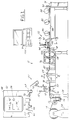
- a fin mill machine 12 illustrated in Figs. 1 - 6 is employed for pulling flat strip stock 14 into it and producing finished fin strips 16 having precisely formed corrugations (fins) 18 therein.
- corrugations corrugations
- Of particular significance to assure an accurately finished product are the consistency of height from corrugation-to-corrugation (fin-to-fin), which is determined by the tension control subsystem 20 and an accurate and continuous measurement of the average height of the heat exchanger fins, which is determined by the height measurement subsystem 22.
- the flat strip stock 14 is secured to a base 24 and fed through three guide rollers 26 before feeding into the tension control subsystem 20, which is mounted to a fin machine base 28.
- the tension control subsystem 20 includes a mounting block 30 mounted to the fin machine base 28 aligned with a pneumatic cylinder 32 having a plunger 34 protruding therefrom toward the mounting block 30.
- Two pieces of frictional material 36 such as cardboard or felt pads, surround the strip stock 14 as it extends between the mounting block 30 and plunger 34.
- One piece 36 is mounted on the block 30 and the other piece 36 is mounted on the plunger 34.
- the friction pads 36 are inexpensive, and easy to routinely replace, thus minimising maintenance costs.
- the strip stock next threads through three rollers 38, 40 and 42, with the middle roller 40 having a material strain gauge 44 mounted therein.
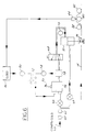
- the strain gauge 44 is electrically connected to a signal conditioner and strain gauge indicator controller 46 mounted in a tension control cabinet 48.
- the indicator controller 46 is electrically connected to a volt meter 50 for strain gauge output.
- This meter 50 reflects the feedback signal to a proportional valve 56. It is electrically connected to a feedback control switch 52. Also electrically connected to this switch 52 is a meter 54 indicating pneumatic cylinder pressure directly, and the proportional valve 56 is electrically connected to the output of this switch 52.
- a tension pot 59 sets the proportional valve 56 to the nominal desired pressure.
- This switch 52 in a first position, then, allows for feedback control to the proportional valve 56 directly from the strain gauge 44 through the volt meter 50 based on the tension in the strip 14.
- the switch 52 in a second position allows for feedback control of the air pressure in the pneumatic cylinder 32 by the meter 54 via a pressure transducer 58 that is electrically connected to the meter 54 and connected to the output of air pressure from the proportional valve 56.
- the switch 52 would be placed in the first position for automatic closed loop feedback control based directly on the tension measured in the strip stock 14.
- the second position employing feedback based on air pressure, is available to be used for more of a manual feedback control, with an indirect indication of the tension in the strip stock 14. In this way, during set-up or trouble shooting of the machine, or if the strain gauge should need servicing, the overall fin machine 12 can still be operated, thus, reducing down time of the machine.
- the air pressure circuit begins with compressed air fed in from a conventional source, not shown, in a manufacturing plant that produces pressurised air for the operation of pneumatic tools.
- the compressed air flows through a 5 ⁇ filter 60 and then a coalescent filter 62.
- the pressurised air then branches off, one branch leading to the pneumatic cylinder 32 through a low pressure regulator 64, used for applying a pressure in the lower portion of the cylinder to raise the plunger 34, and the other branch leads to the proportional valve 56 through a relatively higher pressure regulator 66.
- a servo-valve could be used instead of the proportional valve 56, eliminating the need for the low pressure regulator 64.
- a manual override valve 68 which allows the pneumatic cylinder 32 to be raised manually, should the need arise, and a pressure gauge 70 for displaying the current pressure in the cylinder.
- a conventional star wheel forming station 76 and a form roller 78 are mounted to the fin machine base 28, which form the corrugations 18 in the strip stock 14.
- Packing stations 80, 82 and 84 are mounted on the machine base 28 downstream of the form roller 78, which limit the forward movement of the newly formed corrugations 18, thus packing the corrugations tightly together.
- the strip stock 14 extends through the forming station 76 and the form roller 78 and is received between a pair of fin guards 86, which form a passage tunnel 88 that retains and guides the packed fins in the machine.
- the fin guards 86 are mounted to the fin machine base 28.
- a conventional cutting mechanism 90 is employed to cut the fin strips to the proper length before the finished fins 16 leave the machine.
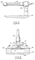
- the height measurement subsystem 22 Mounted between the form roller 78 and the first packing station 80 is the height measurement subsystem 22. It includes a base 92, mounted to the fin guards 86, with the base 92 having three holes therethrough. A sensor 94 is secured in and protrudes through one of the holes. A pair of alignment pins 96 slide through the other two holes on either side of the sensor 94 and are affixed to a ski pad 98, which rests on the packed fins between the fin guards 86. A pair of gauge springs 100 are mounted on the pins 96 between the ski pad 98 and the base 92 and bias the ski pad 98 downward onto the packed fins. The sensor 94 includes a head 102 that telescopes out from the sensor until it is in surface contact with the ski pad 98.
- the sensor 94 is electronically connected to an averaging amplifier and display 104.
- the sensor head 102 itself is a spring loaded device, although it could be weighted instead of spring loaded. Either a spring or a weight can be used because the fins 18 are packed and increased spring load or weight will not squash or mis-shape the fins 18. This allows for the contact of sensor head 102, with no need for an optical sensor and a gap, making the sensor cheaper than an optical gauge, although an optical sensor can be used if so desired.
- the strain gauge 44 is calibrated to determine a correspondence between the tension in the strip stock 14 and the measured value of the strain gauge 44.
- the calibration test consists of hanging a known accurate weight from the strip stock 14 upstream of the pneumatic cylinder 32, and reading the value of the strain gauge 44, then the strain gauge 44 is adjusted to read the known actual weight.
- the air cylinder 32 is used to apply drag, via the friction pads 36, creating a tension in the stock 14.
- the amount of material strip tension determines the fine adjustment of fin height.
- An operator uses a command signal to set the desired material tension via the proportional valve 56 and cylinder 32.
- the proportional air servo valve 56 determines the amount of pressure applied by the pneumatic cylinder 32.
- strain gauge indicator controller 46 receives a feedback signal from the material tension strain gauge transducer 44. The controller 46 compares the measured tension to the desired tension and adjusts the servo valve 56 accordingly.
- the air cylinder 32 is able to maintain very constant material strip tension.
- switch 52 can be moved and the pressure controlled by meter 54 based on pressure readings from transducer 58.
- the strip 14 is fed through the star wheel forming station 76 and the form rollers 78 that cut and form the part into corrugations.
- the first packing station 80 rotates at a slower rate than the form rollers 78, causing the fins 18 to become packed tightly together.
- the sensor head 102 rides continuously on the ski pad 98 that is in direct contact with the fins 18 in the packed state as they flow through the machine.
- the ski pad 98 is used for two reasons, the first is to hold the fins 18 down to the bottom of the passage tunnel 88 for a stable, accurate reading; the second reason for the ski pad 98 is to cover a wider area that the sensor head 102 alone would cover.
- the sensor continuously measures the fin height at the density station while the fins 18 are moving through the machine.
- the key here is that the measurement is taken when the fins are in a packed formation as opposed to an unpacked formation as generated at the output of the machine, where the fins are more unstable and thus more difficult to accurately measure on a continuous basis.
- the packed state allows more force to be used on the fins to hold them down, and get a more consistent reading.
- the changes in height measured at the height measurement subsystem 22 when the tension is changed is near equivalent to the change in fin height in the unpacked finished state for small adjustments in height. Also, although the fin height at the density station is not equal to the final output part height there is a correlation between the height at the density stations and height of the finished parts when unpacked. The fin height difference between the measuring location and the final output part are directly related and can be determined during machine set-up.
- This measured height value can then be sent to the averaging amplifier and display 104 for operator control, accounting for the ratio of height in the packed and finished state by creating a deviation value, to manually adjust the tension in the strip stock 14 by adjusting the pressure in the pneumatic cylinder 32, to correct the average fin height.
- the system preferably employs an averaging of the continuous height measurement over a predetermined time interval to determine the height measurement used for the correction. Specification of both the time period for measurement and the number of samples per value can be specified by inputting them into the averaging amplifier 104.
- a count roller tracks the correct number of corrugations and holds the fins while the cutting mechanism 90 cuts the finished parts 16 to the required length.
- the finished part 16 is held to a specific output density requirement (convolutions per inch or more frequently termed as fins per decimetre). Due to the springback of the material, the cutter is required to pack the fin tightly so that when it is released, it maintains the correct density.
- FIG. 7 A first alternate embodiment is shown in Fig. 7.
- the fin mill machine is essentially unchanged, except for the location of the height measurement subsystem 22'.
- the subsystem 22' is mounted between the first packing station 80 and the second packing station 82. Since the fins are also in a packed state at this location, the height can again be accurately measured.
- FIG. 8 A second alternate embodiment is shown in Fig. 8.
- the height averaging amplifier and display is eliminated and an averaging amplifier and comparator 108 are connected to the sensor 94 and incorporated into the tension control circuit, creating a direct feedback loop that adjusts the desired tension for the strip stock based on the fin height measurement.
- an automatic continuous fin height correction device rather than just an automatic fin height monitoring device.
- the height measurement signal can further be sent to a conventional digital computer 106 to directly compute conventional quality charts used in manufacturing facilities which calculate and plot statistical values such as X-BAR and R charts, (X-Bar being the average of the read averages for a given interval, and R being the range of those values, the difference between the highest and lowest value, within that given interval over which X-Bar is calculated). These can be sent to a conventional printer, not shown, for plotting to allow for monitoring of machine performance for maintenance and repairs.
- X-BAR and R charts X-Bar being the average of the read averages for a given interval, and R being the range of those values, the difference between the highest and lowest value, within that given interval over which X-Bar is calculated.
Landscapes
- Engineering & Computer Science (AREA)
- Mechanical Engineering (AREA)
- Controlling Rewinding, Feeding, Winding, Or Abnormalities Of Webs (AREA)
- Metal Rolling (AREA)
- Length Measuring Devices With Unspecified Measuring Means (AREA)
Applications Claiming Priority (2)
| Application Number | Priority Date | Filing Date | Title |
|---|---|---|---|
| US563253 | 1995-11-27 | ||
| US08/563,253 US5640871A (en) | 1995-11-27 | 1995-11-27 | Fin height measurement for a fin mill machine |
Publications (2)
| Publication Number | Publication Date |
|---|---|
| EP0775540A1 true EP0775540A1 (de) | 1997-05-28 |
| EP0775540B1 EP0775540B1 (de) | 2000-07-26 |
Family
ID=24249743
Family Applications (1)
| Application Number | Title | Priority Date | Filing Date |
|---|---|---|---|
| EP96308159A Expired - Lifetime EP0775540B1 (de) | 1995-11-27 | 1996-11-12 | Vorrichtung zur Herstellung von gewellten Band |
Country Status (4)
| Country | Link |
|---|---|
| US (1) | US5640871A (de) |
| EP (1) | EP0775540B1 (de) |
| KR (1) | KR970025758A (de) |
| DE (1) | DE69609476T2 (de) |
Cited By (2)
| Publication number | Priority date | Publication date | Assignee | Title |
|---|---|---|---|---|
| WO2001078916A3 (en) * | 2000-04-19 | 2002-08-15 | Cosmotec S P A | High thermal efficiency heat exchanger, partially corrugated sheet metal for heat exchangers, plant and procedure for obtaining said partially corrugated sheet metal |
| EP1834713A1 (de) * | 2006-03-16 | 2007-09-19 | Calsonic Kansei Corporation | Vorrichtung zur Herstellung von Wellblechen |
Families Citing this family (3)
| Publication number | Priority date | Publication date | Assignee | Title |
|---|---|---|---|---|
| US5937682A (en) * | 1998-08-28 | 1999-08-17 | Ford Motor Company | Fail-safe fin mill machine wrap-up detector |
| CN103949516A (zh) * | 2014-05-16 | 2014-07-30 | 吴江通信电缆厂 | 一种用于钢带铝带的轧纹装置 |
| DE102021209091B4 (de) | 2021-08-18 | 2023-09-28 | ZELTWANGER Holding GmbH | Verfahren zum Betreiben einer Wellrippenherstellungseinrichtung sowie entsprechende Wellrippenherstellungseinrichtung |
Citations (5)
| Publication number | Priority date | Publication date | Assignee | Title |
|---|---|---|---|---|
| US3367161A (en) | 1965-08-18 | 1968-02-06 | Hrant J. Avakian | Louvered zigzag fin strip forming machine |
| JPS63101028A (ja) | 1986-10-17 | 1988-05-06 | Calsonic Corp | コルゲ−トフインの製造装置 |
| US4753096A (en) | 1986-12-04 | 1988-06-28 | Wallis Bernard J | Apparatus for controlling height of corrugations formed in a continuous length of strip stock |
| JPH03243222A (ja) | 1990-02-19 | 1991-10-30 | Mitsubishi Heavy Ind Ltd | フィン成形装置 |
| US5069053A (en) * | 1989-06-05 | 1991-12-03 | Wallis Bernard J | Method and apparatus for cutting corrugated webs |
Family Cites Families (10)
| Publication number | Priority date | Publication date | Assignee | Title |
|---|---|---|---|---|
| US2329789A (en) * | 1939-11-16 | 1943-09-21 | Mccord Radiator & Mfg Co | Apparatus for making heatexchange elements |
| US2975817A (en) * | 1958-05-29 | 1961-03-21 | Gen Motors Corp | Corrugating machines |
| JPS51127988A (en) * | 1975-04-30 | 1976-11-08 | Ishikawajima Harima Heavy Ind Co Ltd | Tension control device having looper and this looper |
| CA1029580A (en) * | 1975-08-29 | 1978-04-18 | B And K Machinery International Limited | Rotary embosser and process of embossing strip sheet metal |
| JPS57168716A (en) * | 1981-04-10 | 1982-10-18 | Mitsubishi Heavy Ind Ltd | Tension controlling method of rolling material |
| JPS5942135A (ja) * | 1982-09-02 | 1984-03-08 | Nippon Steel Corp | 薄板波加工装置 |
| JPS5942137A (ja) * | 1982-09-02 | 1984-03-08 | Nippon Steel Corp | 薄板波加工装置 |
| US4953378A (en) * | 1989-01-13 | 1990-09-04 | Wallis Bernard J | Apparatus for cutting corrugated strip stock at variable lengths |
| US5022161A (en) * | 1990-08-27 | 1991-06-11 | Carrier Corporation | Plate fin collar gauging apparatus |
| US5207083A (en) * | 1991-12-06 | 1993-05-04 | General Motors Corporation | Method of controlling the length of corrugated fins |
-
1995
- 1995-11-27 US US08/563,253 patent/US5640871A/en not_active Expired - Fee Related
-
1996
- 1996-08-31 KR KR1019960037487A patent/KR970025758A/ko not_active Withdrawn
- 1996-11-12 DE DE69609476T patent/DE69609476T2/de not_active Expired - Fee Related
- 1996-11-12 EP EP96308159A patent/EP0775540B1/de not_active Expired - Lifetime
Patent Citations (5)
| Publication number | Priority date | Publication date | Assignee | Title |
|---|---|---|---|---|
| US3367161A (en) | 1965-08-18 | 1968-02-06 | Hrant J. Avakian | Louvered zigzag fin strip forming machine |
| JPS63101028A (ja) | 1986-10-17 | 1988-05-06 | Calsonic Corp | コルゲ−トフインの製造装置 |
| US4753096A (en) | 1986-12-04 | 1988-06-28 | Wallis Bernard J | Apparatus for controlling height of corrugations formed in a continuous length of strip stock |
| US5069053A (en) * | 1989-06-05 | 1991-12-03 | Wallis Bernard J | Method and apparatus for cutting corrugated webs |
| JPH03243222A (ja) | 1990-02-19 | 1991-10-30 | Mitsubishi Heavy Ind Ltd | フィン成形装置 |
Cited By (3)
| Publication number | Priority date | Publication date | Assignee | Title |
|---|---|---|---|---|
| WO2001078916A3 (en) * | 2000-04-19 | 2002-08-15 | Cosmotec S P A | High thermal efficiency heat exchanger, partially corrugated sheet metal for heat exchangers, plant and procedure for obtaining said partially corrugated sheet metal |
| US6915675B2 (en) | 2000-04-19 | 2005-07-12 | Cosmotec S.P.A. | High thermal efficiency heat exchanger, partially corrugated sheet metal for heat exchangers, plant and procedure for obtaining said partially corrugated sheet metal |
| EP1834713A1 (de) * | 2006-03-16 | 2007-09-19 | Calsonic Kansei Corporation | Vorrichtung zur Herstellung von Wellblechen |
Also Published As
| Publication number | Publication date |
|---|---|
| US5640871A (en) | 1997-06-24 |
| KR970025758A (ko) | 1997-06-24 |
| DE69609476T2 (de) | 2000-12-14 |
| DE69609476D1 (de) | 2000-08-31 |
| EP0775540B1 (de) | 2000-07-26 |
Similar Documents
| Publication | Publication Date | Title |
|---|---|---|
| JP3010426B2 (ja) | ワークからウェーハを切断するためのワイヤ鋸及び切断方法 | |
| US4514348A (en) | Method and apparatus for adjusting die clearance | |
| US5043111A (en) | Process and apparatus for the manfuacture of dimensionally accurate die-formed parts | |
| US4486841A (en) | Bending press | |
| US2792730A (en) | Metal forming | |
| US20060137418A1 (en) | Methods and apparatus for monitoring and conditioning strip material | |
| US7757526B2 (en) | Method for changing force control gain and die cushion control apparatus | |
| US4753096A (en) | Apparatus for controlling height of corrugations formed in a continuous length of strip stock | |
| KR910011349A (ko) | 압연기용 두께 제어 시스템 | |
| EP0936059B1 (de) | Welleinrichtung und Verfahren zur Herstellung von Wellenpappen | |
| US5628221A (en) | Fin mill machine | |
| US4810179A (en) | Force indicator for casting machines | |
| JP3646889B2 (ja) | シート材切断機の刃物用パイロット装置 | |
| EP0775540B1 (de) | Vorrichtung zur Herstellung von gewellten Band | |
| PL198786B1 (pl) | Urządzenie do i sposób kalibrowania prostownicy wielorolkowej | |
| US5758535A (en) | Method of producing corrugated fins | |
| KR20210108649A (ko) | 가변 롤포밍 장치 | |
| CN110508627A (zh) | 电磁调控轧辊调控能力综合测试平台及测试方法 | |
| US5640870A (en) | Tension control of a fin forming device | |
| JP2002542945A (ja) | 調整可能監視ガイド | |
| GB2270570A (en) | A weighing process and belt weigher for carrying out the process | |
| US4954719A (en) | Sheet thickness gauging method and system with auto calibration | |
| EP0500324B1 (de) | Verfahren und Vorrichtung zur Steuerung der hydraulischen Anstellung in einem Walzwerk | |
| US4325248A (en) | Device for measuring thickness of storage cell plates in sorting | |
| ITMI981338A1 (it) | Procedimento per comandare o regolare un dispositivo per applicare un fluido liquido o pastoso su una controsuperficie |
Legal Events
| Date | Code | Title | Description |
|---|---|---|---|
| PUAI | Public reference made under article 153(3) epc to a published international application that has entered the european phase |
Free format text: ORIGINAL CODE: 0009012 |
|
| AK | Designated contracting states |
Kind code of ref document: A1 Designated state(s): DE FR GB |
|
| 17P | Request for examination filed |
Effective date: 19971020 |
|
| 17Q | First examination report despatched |
Effective date: 19971216 |
|
| GRAG | Despatch of communication of intention to grant |
Free format text: ORIGINAL CODE: EPIDOS AGRA |
|
| GRAG | Despatch of communication of intention to grant |
Free format text: ORIGINAL CODE: EPIDOS AGRA |
|
| GRAG | Despatch of communication of intention to grant |
Free format text: ORIGINAL CODE: EPIDOS AGRA |
|
| GRAH | Despatch of communication of intention to grant a patent |
Free format text: ORIGINAL CODE: EPIDOS IGRA |
|
| GRAH | Despatch of communication of intention to grant a patent |
Free format text: ORIGINAL CODE: EPIDOS IGRA |
|
| GRAA | (expected) grant |
Free format text: ORIGINAL CODE: 0009210 |
|
| AK | Designated contracting states |
Kind code of ref document: B1 Designated state(s): DE FR GB |
|
| REF | Corresponds to: |
Ref document number: 69609476 Country of ref document: DE Date of ref document: 20000831 |
|
| PGFP | Annual fee paid to national office [announced via postgrant information from national office to epo] |
Ref country code: DE Payment date: 20001102 Year of fee payment: 5 |
|
| ET | Fr: translation filed | ||
| PLBE | No opposition filed within time limit |
Free format text: ORIGINAL CODE: 0009261 |
|
| STAA | Information on the status of an ep patent application or granted ep patent |
Free format text: STATUS: NO OPPOSITION FILED WITHIN TIME LIMIT |
|
| 26N | No opposition filed | ||
| PGFP | Annual fee paid to national office [announced via postgrant information from national office to epo] |
Ref country code: GB Payment date: 20011012 Year of fee payment: 6 |
|
| PGFP | Annual fee paid to national office [announced via postgrant information from national office to epo] |
Ref country code: FR Payment date: 20011106 Year of fee payment: 6 |
|
| REG | Reference to a national code |
Ref country code: GB Ref legal event code: IF02 |
|
| PG25 | Lapsed in a contracting state [announced via postgrant information from national office to epo] |
Ref country code: DE Free format text: LAPSE BECAUSE OF NON-PAYMENT OF DUE FEES Effective date: 20020702 |
|
| PG25 | Lapsed in a contracting state [announced via postgrant information from national office to epo] |
Ref country code: GB Free format text: LAPSE BECAUSE OF NON-PAYMENT OF DUE FEES Effective date: 20021112 |
|
| GBPC | Gb: european patent ceased through non-payment of renewal fee | ||
| PG25 | Lapsed in a contracting state [announced via postgrant information from national office to epo] |
Ref country code: FR Free format text: LAPSE BECAUSE OF NON-PAYMENT OF DUE FEES Effective date: 20030731 |
|
| REG | Reference to a national code |
Ref country code: FR Ref legal event code: ST |