EP0775769A1 - Dispositif pour pincer le fil de sous-renvidage à une broche d'un métier à filer ou à retordre - Google Patents
Dispositif pour pincer le fil de sous-renvidage à une broche d'un métier à filer ou à retordre Download PDFInfo
- Publication number
- EP0775769A1 EP0775769A1 EP95118470A EP95118470A EP0775769A1 EP 0775769 A1 EP0775769 A1 EP 0775769A1 EP 95118470 A EP95118470 A EP 95118470A EP 95118470 A EP95118470 A EP 95118470A EP 0775769 A1 EP0775769 A1 EP 0775769A1
- Authority
- EP
- European Patent Office
- Prior art keywords
- clamping
- collar
- clamping sleeve
- spindle
- actuating
- Prior art date
- Legal status (The legal status is an assumption and is not a legal conclusion. Google has not performed a legal analysis and makes no representation as to the accuracy of the status listed.)
- Granted
Links
- 238000009987 spinning Methods 0.000 title description 6
- 238000007378 ring spinning Methods 0.000 claims abstract description 12
- 230000009471 action Effects 0.000 claims description 8
- 238000005520 cutting process Methods 0.000 claims description 6
- 229910000831 Steel Inorganic materials 0.000 claims description 2
- 239000000463 material Substances 0.000 claims description 2
- 239000010959 steel Substances 0.000 claims description 2
- 230000003213 activating effect Effects 0.000 abstract 1
- 210000002105 tongue Anatomy 0.000 description 10
- 238000010276 construction Methods 0.000 description 6
- 230000009467 reduction Effects 0.000 description 3
- 238000006073 displacement reaction Methods 0.000 description 2
- 230000008901 benefit Effects 0.000 description 1
- 230000003993 interaction Effects 0.000 description 1
- 238000004519 manufacturing process Methods 0.000 description 1
- 238000000034 method Methods 0.000 description 1
- 230000001105 regulatory effect Effects 0.000 description 1
- 238000004804 winding Methods 0.000 description 1
Images

Classifications
-
- D—TEXTILES; PAPER
- D01—NATURAL OR MAN-MADE THREADS OR FIBRES; SPINNING
- D01H—SPINNING OR TWISTING
- D01H1/00—Spinning or twisting machines in which the product is wound-up continuously
- D01H1/14—Details
- D01H1/38—Arrangements for winding reserve lengths of yarn on take-up packages or spindles, e.g. transfer tails
Definitions
- the invention relates to a device for clamping an underwind thread on the spindle of a ring spinning or twisting machine, the spindle below an attached cop, a fixed collar and an axially displaceable to the spindle by means of an actuating device, which can be brought into clamping operative connection with the collar and the underwind thread wraps around the spindle with less than 360 °.
- Such a device is used to prevent underwind threads from remaining on the spindles.
- a device for this purpose is already known as prior art (EP 0 292 856 A1), in which a clamping sleeve is used which has multiple slots in the lower region over its circumference. This slotted area interacts with a correspondingly designed area of another sleeve in such a way that, under the action of centrifugal force, the slotted area of the first clamping sleeve detaches from the adjacent area of the other sleeve and thus the effective clamping connection to the collar is released.
- the prior art also includes a spinning device, in particular a ring spinning machine (EP 0 582 545 A1), in which an underwind crown sits on a spindle shaft and is arranged in a whorl.
- a sliding sleeve with an inner and outer flange is used, on which a projection of an actuating element strikes.
- the sliding sleeve is in this case moved against the force of a spring arranged between the inner flange and a ring edge in such a way that the underwind crown either comes out of or into a receiving trough above the inner flange.
- a wear ring is used, which is assigned to the outer flange. The problem to be solved here was to use the wear ring to reduce the signs of wear that can occur during spinning and spinning.
- Another prior art relates to an arrangement for actuating a fixing sleeve for a ring spinning or twisting machine (EP 0 587 526 A1).
- a link control is used, which makes it possible to move the fixing sleeve into the various required positions, unaffected by the instantaneous values of the parameters of a run spinning or piecing program.
- This gate control requires precise production, which in turn is expensive.
- the object of the present invention is to design a device of the type mentioned in such a way that a considerable reduction in wear is achieved with a cost-saving structure.
- the actuating device provided with at least one actuating element is fixed to the ring spinning or twisting machine, that the actuating element can only be brought into contact with the clamping sleeve for actuation, and that a device is provided by which the clamping sleeve is held in the clamping position regardless of the action of the actuating device.
- This has the advantage, among other things, that wear is reduced, since the actuating element is only activated for actuation with the clamping sleeve, and in addition a reduction in the design effort is achieved due to the fixed arrangement of the actuating device on the ring spinning or twisting machine.
- the clamping operative connection between the collar and the clamping sleeve can be self-locking to hold the clamping sleeve in the clamping position, which results in a considerable reduction in the construction effort.
- the actuating element can each be designed as an arm encompassing at least one collar of the clamping sleeve on both sides or an arm that can be acted upon on both sides and projecting between two collars of the clamping sleeve, as at least one resilient tongue, as half-shafts, as at least one rail or as a threaded element be.
- pneumatic, mechanical or magnetic drives to move the individual elements of the actuating device.
- a particularly simple and cost-saving, but very effective construction is obtained if at least one inflatable hose extending along the machine is used for the pneumatic drive of the actuating device.
- This hose is a known, commercially available element which can be arranged along the machine without great assembly or construction work.
- this can have a clamping cone which interacts with a clamping cone of the fixed collar of the sleeve.
- a cutting knife can be used in the area of the fixed collar, whereby it is ensured that the tearing off of the underwind thread is supported in the event of insufficient clamping.
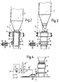
- FIG. 1 shows a cross section through a spindle bench 1 and a ring bench 3 at a work station of a ring spinning machine, which is defined by a spindle 2 on which a cop 4 is supported.
- a thread 5 runs through a runner 6 to an area below a fixed collar 9 and forms part of an underwind thread 7 in this zone.
- the spindle 2 is surrounded below the fixed collar 9 by a clamping sleeve 8 which has two bundles 15 and 16 which are spaced apart from one another in the lower region.
- An actuating element 11, which is part of an actuating device 10, projects between these bundles.
- the actuating device 10 is connected to a pneumatic or hydraulic drive 30.
- a device 12 is provided, by means of which the clamping sleeve 8 is held in a clamping position K (according to FIG. 2) independently of the actuating device 10.
- This can - preferably - be achieved in that the closed position of the clamping sleeve 8 is self-locking or that a locking element with a suit (for example, a ball pressure lock acting on a ramp) is arranged between the spindle and the clamping sleeve.
- the actuating element 11 is designed in the form of an arm 20, the front region of which projects into the space between the bundles 15 and 16.
- the drive 30 consists of a motor 43, a pump 44, control devices 45 and 45 'and switching valves 46 and 47. If, for example, the switching valve 47 is moved downwards with the aid of the control device 45', medium passes through the pump 44 and a line 60 into the hose 41, which expands it so that the arm 20 is loaded from below and lifts it.
- Fig. 1 shows the starting position for the winch: the clamping sleeve 8 is lowered, the hoses 40 and 41 are not acted upon, the actuating element 11, ie the arm 20 is not on the frets 15 and 16, the spindle 2 makes its last rotation corresponding to the thread balloon of thread 5, a half turn, as shown in dash-dotted lines, is attached.
- the lower hose 41 is acted upon with the aid of the control device 45 'and the switching valve 47, so that the arm 20 lifts the clamping sleeve 8 via the collar 15.
- the underwind thread 7 is clamped between the fixed collar 9 and the upper region of the clamping sleeve 8; this results in the clamping position K.
- the clamping sleeve 8 cooperates with the fixed collar 9 in such a way that it is independent of the action of the actuating device 10, i.e. the arm 20 is held in the clamping position K.
- the lower hose 41 is relieved again by the action of the control device 45 'and the switching valve 47.
- the arm 20 returns to its rest position in which it is not in contact with any of the bundles 15 and 16.
- the cop 4 is pulled off, the underwind thread 7 in region X is torn off.
- the upper hose 40 is acted upon by the control device 45 and the switching valve 46, as a result of which the arm 20 acts on the collar 16 and separates the clamping sleeve 8 from its clamping position K from the collar 9.
- the pinching of the underwind thread 7 is released.
- the clamping sleeve 8 may only be lowered after the re-spinning, when the thread is again held by the newly constructed winding and no longer needs to be clamped.
- FIG. 4 shows an embodiment in which only one hose 40 'is used.
- the hose 40 ' is connected via a line 61' to a drive 31, which in turn has a motor 43 and a pump 44, as in FIG. 1.
- a control device 45 ′′ and a switching valve 47 ′ with the switching positions a, b, c are provided.
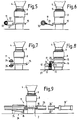
- the actuating member 11 is designed in the form of two resilient tongues 22 and 22 ′, which are fastened to a rotatable shaft 32. Both tongues comprise the single collar 15 of the clamping sleeve 8.
- the illustration shows the normal position.
- the tongue 22 By pivoting the shaft 32 counterclockwise, the tongue 22 'bears against the collar 15 and lifts the clamping sleeve into the clamping position.
- the clamping sleeve 8 can be released from the clamping position by pivoting the shaft 32 in a clockwise direction by placing the tongue 22 on the collar 15.
- the actuating element 11 is designed in the form of two alternately rotatable camshafts 24 and 24 ', by means of which the clamping sleeve 8 can be raised or lowered with respect to the collar 9:
- the lower camshaft 24' is rotated and acts on the collar 15, whereby the clamping sleeve 8 is lifted into the region of the fixed collar 9.
- the federal government 15 thus occupies the dashed position. If the clamping K is to be released, the camshaft 24 acts on the collar 15 from above and guides the clamping sleeve 8 back from the clamping position K into the rest position.
- the camshafts 24, 24 ' are each rotated back and forth by 180 ° or by 360 °, so that they always return to the drawn rest position, in which they do not rest on the collar 15.
- the cams arranged on the camshafts can have any shape.
- the camshafts could also be cylindrical, but rotatable about an eccentric axis.
- the embodiment according to FIG. 8 provides a rail 25 which can be stored between two bundles 15 and 16 and which is connected to a drive 33 in the form of a piston-cylinder unit 51.
- the rail 25 can be raised or lowered via a pin connected to the piston of the piston-cylinder unit 51.
- the piston of the piston-cylinder unit is acted upon on both sides by a spring 71 and 72, by means of which the piston and thus the rail 25 are held in the middle rest position, as shown in FIG. 8.
- the piston sides are acted upon via one of two channels 73 and 74, whereby the rail 25 is either raised or lowered.
- the actuating element 11 is designed in the form of a longitudinally displaceable rail 26 which is guided on ramps 75 and 76 which form the drive 34 during the longitudinal displacement.
- the ramp 75 is fixed to the machine, the ramp 76 is connected to the rail 26.
- the rail 26 has two webs 26 'and 26' 'which comprise the collar 15.
- the rail 26 is connected to a piston-cylinder unit 51 ', as a result of which it can be moved longitudinally and, in cooperation with the ramps 75 and 76 and the webs 26' and 26 '', moves the clamping sleeve 8 vertically.
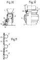
- FIG. 10 and 11 show another embodiment with a rail 53, which is part of a drive.
- This rail 53 runs over the entire length of the machine and is displaceable at the end by means of an actuating device, not shown, for example according to the embodiment according to FIG. 9.
- This rail has webs 54, which each over strips are provided with an elastic covering 56. The webs 54 with the strips and the elastic coverings 56 are in the rest position according to FIG. 11 between the spindles.
- the rail 53 is displaced such that the elastic coverings 56 act on the outer circumference of the clamping sleeve 8 ', which in turn are each provided with a pin.
- This pin 27 engages in a thread 28 of the spindle 2 concerned.
- the clamping sleeve 8 ′ rotates upward during the longitudinal displacement of the rail 53 under the action of the elastic covering 56 and reaches the upper region thereof Effective range of the fixed sleeve 9.
- the clamping sleeve 8 is thus rotated upwards by the thread pitch 28.
- the rail 53 must be moved so far that the bar and the elastic covering 56 are in the next gap between the spindles, so that the rotation of the spindles is not hindered when they restart.
- the elastic covering 56 and the webs 54 (with the spindles running counter to the direction of rotation) must be pulled back into the starting position according to FIG. 10.
- the webs 54 with the elastic coverings 56 may therefore not be longer than is necessary for the passage of the thread 28.
- the rail 53 is a shaft and pivotable, so that the webs 54 can be pivoted away from the spindles 2 if they are not to come into operative connection with the clamping sleeves 8 'or if they are to be moved back in their starting position.
- a further pivotable element is required in addition to the work element to be moved.
- the clamping sleeve 8 above the collar region can be fixed with a clamping cone 39 ' Have collar 9 of the spindle 2 interacting clamping cone 39.
- the clamping cones 39 and 39 'of the clamping sleeve 8 and the fixed collar 9 are formed with a lower small diameter.
- the self-retention is given regardless of the presence of a thread 7. In some cases it is sufficient if there is self-retention when a thread has to be clamped. It follows from this that the clamping surfaces can also be cylindrical if their fit is so tight or the thread is so thick that self-retention is achieved by the two areas of the underwind thread lying between them.
- the underwind thread 7 should tear between the clamping area and the cop 4 (corresponding to representation X in FIG. 3), so that no cutting knife is required. If there is insufficient clamping, for example in the case of very tear-resistant threads, the underwind thread 7 could, however, be pulled out of the clamping area and not be torn off. In this case, the cutting knife 55 can support the tearing off of the underwind thread 7.
- the clamping sleeve 8 or 8 'and the fixed collar 9 can be made of different materials, e.g. Steel and plastic are used to improve the self-locking effective connection between the collar and the clamping sleeve.
Landscapes
- Engineering & Computer Science (AREA)
- Mechanical Engineering (AREA)
- Textile Engineering (AREA)
- Spinning Or Twisting Of Yarns (AREA)
Priority Applications (2)
| Application Number | Priority Date | Filing Date | Title |
|---|---|---|---|
| DE59508008T DE59508008D1 (de) | 1995-11-23 | 1995-11-23 | Vorrichtung zum Klemmen eines Unterwindefadens an der Spindel einer Ringspinn- oder -zwirnmaschine |
| EP19950118470 EP0775769B1 (fr) | 1995-11-23 | 1995-11-23 | Dispositif pour pincer le fil de sous-renvidage à une broche d'un métier à filer ou à retordre |
Applications Claiming Priority (1)
| Application Number | Priority Date | Filing Date | Title |
|---|---|---|---|
| EP19950118470 EP0775769B1 (fr) | 1995-11-23 | 1995-11-23 | Dispositif pour pincer le fil de sous-renvidage à une broche d'un métier à filer ou à retordre |
Publications (2)
| Publication Number | Publication Date |
|---|---|
| EP0775769A1 true EP0775769A1 (fr) | 1997-05-28 |
| EP0775769B1 EP0775769B1 (fr) | 2000-03-15 |
Family
ID=8219829
Family Applications (1)
| Application Number | Title | Priority Date | Filing Date |
|---|---|---|---|
| EP19950118470 Expired - Lifetime EP0775769B1 (fr) | 1995-11-23 | 1995-11-23 | Dispositif pour pincer le fil de sous-renvidage à une broche d'un métier à filer ou à retordre |
Country Status (2)
| Country | Link |
|---|---|
| EP (1) | EP0775769B1 (fr) |
| DE (1) | DE59508008D1 (fr) |
Cited By (6)
| Publication number | Priority date | Publication date | Assignee | Title |
|---|---|---|---|---|
| US6085511A (en) * | 1998-04-09 | 2000-07-11 | Zinser Textilmaschinen Gmbh | Underwinding-thread clamp for a ring-spinning or ring-twisting machine |
| DE19904793C1 (de) * | 1999-02-05 | 2000-08-03 | Zinser Textilmaschinen Gmbh | Vorrichtung zum Klemmen von Unterwindefäden an einer Spinnspindel |
| WO2001025518A1 (fr) * | 1999-10-05 | 2001-04-12 | Koenig Guenter | Dispositif destine a fixer un fil de sous-renvidage sur une broche de machine textile, en particulier d'un metier continu a filer |
| EP1477594A1 (fr) * | 2003-05-13 | 2004-11-17 | Marzoli S.p.A. | Dispositif pour saisir un fil sous-renvidé dans un métier à filer à anneaux |
| WO2007065703A3 (fr) * | 2005-12-08 | 2007-09-27 | Guenter Koenig | Dispositif pince-fil pour des fils de sous-renvidage sur des broches d'un métier à filer à anneaux ou d'un métier à retordre à anneaux |
| DE19964204B4 (de) * | 1999-10-05 | 2010-03-11 | König, Günter | Vorrichtung zum Klemmen eines Unterwindefadens an einer Spindel einer Textilmaschine, insbesondere einer Ringspinnmaschine |
Families Citing this family (1)
| Publication number | Priority date | Publication date | Assignee | Title |
|---|---|---|---|---|
| DE102008053811A1 (de) | 2008-10-27 | 2010-04-29 | König, Günter | Vorrichtung zum Klemmen eines Unterwindefadens an einer Spindel einer Textilmaschine |
Citations (4)
| Publication number | Priority date | Publication date | Assignee | Title |
|---|---|---|---|---|
| EP0142486A1 (fr) * | 1983-10-05 | 1985-05-22 | Société Anonyme des Ateliers Houget Duesberg Bosson | Appareillage pour le contrôle et le réamorçage du fil coupé lors du remplacement des bobines pleines se trouvant sur les broches d'un métier continu à filer par des tubes vides |
| EP0292856A1 (fr) | 1987-05-26 | 1988-11-30 | Odawara Industry Co., Ltd. | Appareil pour traiter le bout d'un fil pour dispositif de broche textile |
| EP0582545A1 (fr) | 1992-08-06 | 1994-02-09 | Maschinenfabrik Rieter Ag | Métier à filer |
| EP0587526A1 (fr) | 1992-09-03 | 1994-03-16 | Maschinenfabrik Rieter Ag | Dispositif pour actionner le tube de fixation pour un métier à filer ou à retordre |
-
1995
- 1995-11-23 EP EP19950118470 patent/EP0775769B1/fr not_active Expired - Lifetime
- 1995-11-23 DE DE59508008T patent/DE59508008D1/de not_active Expired - Fee Related
Patent Citations (5)
| Publication number | Priority date | Publication date | Assignee | Title |
|---|---|---|---|---|
| EP0142486A1 (fr) * | 1983-10-05 | 1985-05-22 | Société Anonyme des Ateliers Houget Duesberg Bosson | Appareillage pour le contrôle et le réamorçage du fil coupé lors du remplacement des bobines pleines se trouvant sur les broches d'un métier continu à filer par des tubes vides |
| EP0142486B1 (fr) | 1983-10-05 | 1987-10-28 | Société Anonyme des Ateliers Houget Duesberg Bosson | Appareillage pour le contrôle et le réamorçage du fil coupé lors du remplacement des bobines pleines se trouvant sur les broches d'un métier continu à filer par des tubes vides |
| EP0292856A1 (fr) | 1987-05-26 | 1988-11-30 | Odawara Industry Co., Ltd. | Appareil pour traiter le bout d'un fil pour dispositif de broche textile |
| EP0582545A1 (fr) | 1992-08-06 | 1994-02-09 | Maschinenfabrik Rieter Ag | Métier à filer |
| EP0587526A1 (fr) | 1992-09-03 | 1994-03-16 | Maschinenfabrik Rieter Ag | Dispositif pour actionner le tube de fixation pour un métier à filer ou à retordre |
Cited By (12)
| Publication number | Priority date | Publication date | Assignee | Title |
|---|---|---|---|---|
| US6085511A (en) * | 1998-04-09 | 2000-07-11 | Zinser Textilmaschinen Gmbh | Underwinding-thread clamp for a ring-spinning or ring-twisting machine |
| DE19904793C1 (de) * | 1999-02-05 | 2000-08-03 | Zinser Textilmaschinen Gmbh | Vorrichtung zum Klemmen von Unterwindefäden an einer Spinnspindel |
| EP1045050A1 (fr) * | 1999-02-05 | 2000-10-18 | Zinser Textilmaschinen GmbH | Méthode et appareil pour pincer un fil de sous-renvidage sur une broche d'un métier à filer |
| US6289662B1 (en) | 1999-02-05 | 2001-09-18 | Zinser Textilmaschinen Gmbh | Method of and apparatus for clamping the underwinding thread of a spinning spindle |
| WO2001025518A1 (fr) * | 1999-10-05 | 2001-04-12 | Koenig Guenter | Dispositif destine a fixer un fil de sous-renvidage sur une broche de machine textile, en particulier d'un metier continu a filer |
| EP1218577A1 (fr) * | 1999-10-05 | 2002-07-03 | Günter König | Dispositif destine a fixer un fil de sous-renvidage sur une broche de machine textile, en particulier d'un metier continu a filer |
| DE19964204B4 (de) * | 1999-10-05 | 2010-03-11 | König, Günter | Vorrichtung zum Klemmen eines Unterwindefadens an einer Spindel einer Textilmaschine, insbesondere einer Ringspinnmaschine |
| EP1477594A1 (fr) * | 2003-05-13 | 2004-11-17 | Marzoli S.p.A. | Dispositif pour saisir un fil sous-renvidé dans un métier à filer à anneaux |
| EP1696058A3 (fr) * | 2003-05-13 | 2007-06-27 | Marzoli S.p.A. | Dispositif pour saisir un fil sous-renvidé dans un métier à filer à anneaux |
| WO2007065703A3 (fr) * | 2005-12-08 | 2007-09-27 | Guenter Koenig | Dispositif pince-fil pour des fils de sous-renvidage sur des broches d'un métier à filer à anneaux ou d'un métier à retordre à anneaux |
| JP2009517558A (ja) * | 2005-12-08 | 2009-04-30 | ケーニヒ、ギュンター | リング精紡機またはリング撚糸機のスピンドル上の下部巻き付け糸用の糸締め付け装置 |
| KR101024293B1 (ko) | 2005-12-08 | 2011-03-29 | 귄터 퀘니히 | 링 방적기 또는 링 연사기의 방추들에 방적사를언더와인딩하는 방적사 클램핑 장치 |
Also Published As
| Publication number | Publication date |
|---|---|
| DE59508008D1 (de) | 2000-04-20 |
| EP0775769B1 (fr) | 2000-03-15 |
Similar Documents
| Publication | Publication Date | Title |
|---|---|---|
| EP2261158B1 (fr) | Bobinoir doté d'un dispositif de changement et procédé de fonctionnement de celui-ci | |
| CH619193A5 (fr) | ||
| EP2256238B2 (fr) | Dispositif de pince-fil pour une broche d'un métier à tisser ou d'une retordeuse | |
| EP0775769B1 (fr) | Dispositif pour pincer le fil de sous-renvidage à une broche d'un métier à filer ou à retordre | |
| EP0949366A2 (fr) | Appareil pour pincer un fil de sous-renvidage sur une broche d'un métier continu à filer ou à retordre à anneau | |
| EP3594390B1 (fr) | Appareil d'alimentation en fil | |
| DE4408262C2 (de) | Einrichtung zum Einstellen von Kapselfadenbremsen an Zwirnmaschinen, insbesondere Doppeldraht-Zwirnmaschinen | |
| DE2406550C3 (fr) | ||
| DE3235789C2 (de) | Schwenkbarer Spulenhalter | |
| DE10133604A1 (de) | Verfahren und Vorrichtung zum Hin- und Herbewegen von Luntenführern | |
| CH676724A5 (fr) | ||
| DE3317267A1 (de) | Fadenzufuehrvorrichtung | |
| EP3587643B1 (fr) | Fournisseur de fil et système doté d'un fournisseur de fil | |
| CH689040GA3 (de) | Verfahren und Vorrichtung zum Texturieren von thermoplastischen Faeden. | |
| DE2621014C2 (de) | Fadenliefervorrichtung für Textilmaschinen | |
| DE3123282C1 (de) | Vorrichtung zur Aufnahme eines Fadens von einer Spule und UEbergabe an ein Arbeitsorgan | |
| EP0734815A1 (fr) | Outils pour Ôter des paliers | |
| EP1785513B1 (fr) | Dispositif et procédé pour la rattache d'un fil | |
| DE2540854C2 (de) | Verfahren zum Bilden von Reservewindungen | |
| DE4410831B4 (de) | Klemmvorrichtung für Faden in Spinnmaschine | |
| EP4163241A1 (fr) | Machine textile produisant des bobines croisées avec une pluralité de postes de travail adjacents similaires et un système à dépression | |
| DE19942722C1 (de) | Aufwickelvorrichtung zur Herstellung zylindrischer Kreuzspulen | |
| DE2533291A1 (de) | Vorspinnmaschine | |
| DE1510523A1 (de) | Steuereinrichtung fuer die Mengenregelung in hydraulischen Changierantrieben von Spul-,Spinn- und insbesondere Ringzwirnmaschinen | |
| DE3516458A1 (de) | Angetriebener fadenspeicher |
Legal Events
| Date | Code | Title | Description |
|---|---|---|---|
| PUAI | Public reference made under article 153(3) epc to a published international application that has entered the european phase |
Free format text: ORIGINAL CODE: 0009012 |
|
| AK | Designated contracting states |
Kind code of ref document: A1 Designated state(s): CH DE FR IT LI |
|
| 17P | Request for examination filed |
Effective date: 19971029 |
|
| 17Q | First examination report despatched |
Effective date: 19971219 |
|
| GRAG | Despatch of communication of intention to grant |
Free format text: ORIGINAL CODE: EPIDOS AGRA |
|
| GRAG | Despatch of communication of intention to grant |
Free format text: ORIGINAL CODE: EPIDOS AGRA |
|
| GRAH | Despatch of communication of intention to grant a patent |
Free format text: ORIGINAL CODE: EPIDOS IGRA |
|
| GRAH | Despatch of communication of intention to grant a patent |
Free format text: ORIGINAL CODE: EPIDOS IGRA |
|
| GRAA | (expected) grant |
Free format text: ORIGINAL CODE: 0009210 |
|
| AK | Designated contracting states |
Kind code of ref document: B1 Designated state(s): CH DE FR IT LI |
|
| REG | Reference to a national code |
Ref country code: CH Ref legal event code: EP |
|
| ITF | It: translation for a ep patent filed | ||
| REF | Corresponds to: |
Ref document number: 59508008 Country of ref document: DE Date of ref document: 20000420 |
|
| ET | Fr: translation filed | ||
| PLBE | No opposition filed within time limit |
Free format text: ORIGINAL CODE: 0009261 |
|
| STAA | Information on the status of an ep patent application or granted ep patent |
Free format text: STATUS: NO OPPOSITION FILED WITHIN TIME LIMIT |
|
| 26N | No opposition filed | ||
| PGFP | Annual fee paid to national office [announced via postgrant information from national office to epo] |
Ref country code: FR Payment date: 20011122 Year of fee payment: 7 |
|
| PGFP | Annual fee paid to national office [announced via postgrant information from national office to epo] |
Ref country code: CH Payment date: 20021126 Year of fee payment: 8 |
|
| PGFP | Annual fee paid to national office [announced via postgrant information from national office to epo] |
Ref country code: DE Payment date: 20030116 Year of fee payment: 8 |
|
| PG25 | Lapsed in a contracting state [announced via postgrant information from national office to epo] |
Ref country code: FR Free format text: LAPSE BECAUSE OF NON-PAYMENT OF DUE FEES Effective date: 20030731 |
|
| REG | Reference to a national code |
Ref country code: FR Ref legal event code: ST |
|
| PG25 | Lapsed in a contracting state [announced via postgrant information from national office to epo] |
Ref country code: LI Free format text: LAPSE BECAUSE OF NON-PAYMENT OF DUE FEES Effective date: 20031130 Ref country code: CH Free format text: LAPSE BECAUSE OF NON-PAYMENT OF DUE FEES Effective date: 20031130 |
|
| PG25 | Lapsed in a contracting state [announced via postgrant information from national office to epo] |
Ref country code: DE Free format text: LAPSE BECAUSE OF NON-PAYMENT OF DUE FEES Effective date: 20040602 |
|
| REG | Reference to a national code |
Ref country code: CH Ref legal event code: PL |
|
| PG25 | Lapsed in a contracting state [announced via postgrant information from national office to epo] |
Ref country code: IT Free format text: LAPSE BECAUSE OF NON-PAYMENT OF DUE FEES;WARNING: LAPSES OF ITALIAN PATENTS WITH EFFECTIVE DATE BEFORE 2007 MAY HAVE OCCURRED AT ANY TIME BEFORE 2007. THE CORRECT EFFECTIVE DATE MAY BE DIFFERENT FROM THE ONE RECORDED. Effective date: 20051123 |