EP0776429B1 - Frein a disque humide - Google Patents
Frein a disque humide Download PDFInfo
- Publication number
- EP0776429B1 EP0776429B1 EP95929648A EP95929648A EP0776429B1 EP 0776429 B1 EP0776429 B1 EP 0776429B1 EP 95929648 A EP95929648 A EP 95929648A EP 95929648 A EP95929648 A EP 95929648A EP 0776429 B1 EP0776429 B1 EP 0776429B1
- Authority
- EP
- European Patent Office
- Prior art keywords
- grooves
- braking surface
- brake pad
- leading
- edge
- Prior art date
- Legal status (The legal status is an assumption and is not a legal conclusion. Google has not performed a legal analysis and makes no representation as to the accuracy of the status listed.)
- Expired - Lifetime
Links
- 239000002783 friction material Substances 0.000 claims abstract description 25
- 230000003247 decreasing effect Effects 0.000 claims description 3
- 239000003921 oil Substances 0.000 description 39
- 239000007788 liquid Substances 0.000 description 28
- 230000002093 peripheral effect Effects 0.000 description 8
- 230000000712 assembly Effects 0.000 description 4
- 238000000429 assembly Methods 0.000 description 4
- 230000000694 effects Effects 0.000 description 4
- 238000005461 lubrication Methods 0.000 description 3
- 239000002245 particle Substances 0.000 description 3
- 230000008901 benefit Effects 0.000 description 2
- 230000007423 decrease Effects 0.000 description 2
- 239000002480 mineral oil Substances 0.000 description 2
- 230000004048 modification Effects 0.000 description 2
- 238000012986 modification Methods 0.000 description 2
- 241001544487 Macromiidae Species 0.000 description 1
- 229910000831 Steel Inorganic materials 0.000 description 1
- 230000009471 action Effects 0.000 description 1
- 230000001154 acute effect Effects 0.000 description 1
- 230000002411 adverse Effects 0.000 description 1
- 238000004378 air conditioning Methods 0.000 description 1
- 230000004075 alteration Effects 0.000 description 1
- 239000000356 contaminant Substances 0.000 description 1
- 239000002826 coolant Substances 0.000 description 1
- 239000012809 cooling fluid Substances 0.000 description 1
- 239000000498 cooling water Substances 0.000 description 1
- 239000012530 fluid Substances 0.000 description 1
- 230000005484 gravity Effects 0.000 description 1
- 230000036541 health Effects 0.000 description 1
- 238000010438 heat treatment Methods 0.000 description 1
- 230000014759 maintenance of location Effects 0.000 description 1
- 239000000463 material Substances 0.000 description 1
- 230000013011 mating Effects 0.000 description 1
- 239000013528 metallic particle Substances 0.000 description 1
- 238000000034 method Methods 0.000 description 1
- 235000010446 mineral oil Nutrition 0.000 description 1
- 238000013021 overheating Methods 0.000 description 1
- 238000000746 purification Methods 0.000 description 1
- 230000000717 retained effect Effects 0.000 description 1
- 229910001220 stainless steel Inorganic materials 0.000 description 1
- 239000010935 stainless steel Substances 0.000 description 1
- 239000010959 steel Substances 0.000 description 1
- 239000000725 suspension Substances 0.000 description 1
- XLYOFNOQVPJJNP-UHFFFAOYSA-N water Substances O XLYOFNOQVPJJNP-UHFFFAOYSA-N 0.000 description 1
- 210000002268 wool Anatomy 0.000 description 1
Images


Classifications
-
- F—MECHANICAL ENGINEERING; LIGHTING; HEATING; WEAPONS; BLASTING
- F16—ENGINEERING ELEMENTS AND UNITS; GENERAL MEASURES FOR PRODUCING AND MAINTAINING EFFECTIVE FUNCTIONING OF MACHINES OR INSTALLATIONS; THERMAL INSULATION IN GENERAL
- F16D—COUPLINGS FOR TRANSMITTING ROTATION; CLUTCHES; BRAKES
- F16D69/00—Friction linings; Attachment thereof; Selection of coacting friction substances or surfaces
-
- F—MECHANICAL ENGINEERING; LIGHTING; HEATING; WEAPONS; BLASTING
- F16—ENGINEERING ELEMENTS AND UNITS; GENERAL MEASURES FOR PRODUCING AND MAINTAINING EFFECTIVE FUNCTIONING OF MACHINES OR INSTALLATIONS; THERMAL INSULATION IN GENERAL
- F16D—COUPLINGS FOR TRANSMITTING ROTATION; CLUTCHES; BRAKES
- F16D65/00—Parts or details
- F16D65/02—Braking members; Mounting thereof
- F16D65/04—Bands, shoes or pads; Pivots or supporting members therefor
- F16D65/092—Bands, shoes or pads; Pivots or supporting members therefor for axially-engaging brakes, e.g. disc brakes
-
- F—MECHANICAL ENGINEERING; LIGHTING; HEATING; WEAPONS; BLASTING
- F16—ENGINEERING ELEMENTS AND UNITS; GENERAL MEASURES FOR PRODUCING AND MAINTAINING EFFECTIVE FUNCTIONING OF MACHINES OR INSTALLATIONS; THERMAL INSULATION IN GENERAL
- F16D—COUPLINGS FOR TRANSMITTING ROTATION; CLUTCHES; BRAKES
- F16D65/00—Parts or details
- F16D65/02—Braking members; Mounting thereof
- F16D65/12—Discs; Drums for disc brakes
- F16D65/128—Discs; Drums for disc brakes characterised by means for cooling
-
- F—MECHANICAL ENGINEERING; LIGHTING; HEATING; WEAPONS; BLASTING
- F16—ENGINEERING ELEMENTS AND UNITS; GENERAL MEASURES FOR PRODUCING AND MAINTAINING EFFECTIVE FUNCTIONING OF MACHINES OR INSTALLATIONS; THERMAL INSULATION IN GENERAL
- F16D—COUPLINGS FOR TRANSMITTING ROTATION; CLUTCHES; BRAKES
- F16D65/00—Parts or details
- F16D65/78—Features relating to cooling
- F16D65/84—Features relating to cooling for disc brakes
- F16D65/853—Features relating to cooling for disc brakes with closed cooling system
-
- F—MECHANICAL ENGINEERING; LIGHTING; HEATING; WEAPONS; BLASTING
- F16—ENGINEERING ELEMENTS AND UNITS; GENERAL MEASURES FOR PRODUCING AND MAINTAINING EFFECTIVE FUNCTIONING OF MACHINES OR INSTALLATIONS; THERMAL INSULATION IN GENERAL
- F16D—COUPLINGS FOR TRANSMITTING ROTATION; CLUTCHES; BRAKES
- F16D69/00—Friction linings; Attachment thereof; Selection of coacting friction substances or surfaces
- F16D2069/004—Profiled friction surfaces, e.g. grooves, dimples
Definitions
- the present invention relates to improvements in disc brake assemblies and components, particularly friction pad configurations.
- Conventional vehicle brakes most commonly comprise a rotor disc with a pair of friction material pads respectively acting on opposed braking surfaces of the rotor disc in a dry environment.
- Such systems have a number of significant disadvantages in that both the disc and particularly the friction material pads wear during use allowing wear particles to be released into the atmosphere which is polluting and may well be a health risk.
- the performance of such brakes is not uniform and varies considerably over time, particularly, as a result of friction pad wear and external factors such as whether water or other liquids get onto the braking surfaces during use.
- wet disc brake forms of wet disc brake are also known where a plurality of friction material discs are provided within a sealed brake housing containing oil.
- Such wet disc brakes have usually utilised oils of 7-8 or higher centistokes mm 2 /sec at 100°C viscosity.
- oils normally also had a low viscosity index of 100 which caused substantial viscosity alterations as the oil temperature changed.
- the discs are provided such that some carrying grooved friction material rotate and other plain discs are stationary and braking effect is achieved by axially forcing the discs together.
- the oil is provided primarily as a coolant and for this purpose oil circulates through the grooves in the rotating discs.
- Oil of 7-8 (or higher) centistokes was, however, considered necessary to promote hydrodynamic lubrication and resistance to pressure "squeeze out" in the interengaged friction zone to suppress stick slip, wear, and localised overheating of the brake friction discs and plates.
- the drawback of utilising hydrodynamic lubrication regime is that a lower friction coefficient results in the interengaged region.
- these oils cause an adverse effect on friction levels, it is necessary to have the much greater braking surface area provided by the plurality of discs.
- the configuration of these systems are generally considerably different to those of the dry friction systems described in the preceding paragraph making it difficult to interchange the respective assemblies.
- a brake assembly for a vehicle of the type comprising a single rotor disc adapted to rotate with an axle end and a stationary housing enclosing the rotor disc with one or more seals acting to provide a substantially sealed but pressure equalised zone surrounding at least a brake effect region of said rotor disc.
- At least one pair of friction pads is provided adapted to be engaged against opposed braking faces of a peripheral zone of the rotor disc, and the housing Is formed so that If can contain a liquid in at least part of the braking zone.
- WO 93/07402 indicates the liquid may be maintained at a level above the seals so as to prevent ingress of contaminants into the interior of the housing and particularly in the area of the braking surfaces and friction pads.
- WO 93/07402 further discloses friction pads including backing plates with friction material secured thereto, the friction material having rotor disc engaging faces with one or more grooves formed therein of particular configuration.
- the aforementioned brake arrangement will, however, benefit from a minimum of liquid or lubrication and the grooves are provided for the purpose of oil skimming and draining from the braking surfaces in contrast to other oil Immersed brake systems where grooves are provided to assist with oil circulation. Further grooved friction pads are disclosed, for example, in FR-A-2640337.
- the objective of the present invention is to provide improved friction material products, particularly brake pads and other components, capable of use in brake assemblies of the type shown in WO 93/07402.
- a further preferred objective Is to provide an improved brake arrangement capable of advantageously using the aforesaid friction material products and other brake assembly components. It is also a preferred objective that the brake arrangement according to the present Invention be such that it is relatively easily interchangeable with the dry friction disc brake assemblies now commonly in use.
- a brake pad including a friction material having a braking surface adapted, in use, to contact a rotor disc of a brake assembly, said braking surface having a leading edge relative to rotation of said rotor disc, an opposed trailing edge, and inner and outer circumferentially extending edges joining said leading and trailing edges, said friction material further including a plurality of grooves formed in said friction material with said grooves opening onto said braking surface and being angled from a leading end of the grooves rearwardly relative to a radial line, at least one of said grooves opening onto the leading edge of said braking surface and said grooves further being curved from their leading end to their trailing end with a convex side of said grooves facing towards the leading edge of the braking surface, said brake pad being characterised in that each of said grooves is of arcuate form throughout its length and in that the trailing end of each of said grooves exits said braking surface at either said trailing edge or said outer circumferentially extending edge.
- the advantage that is achieved by arranging one or more grooves leading from a leading edge of the pad friction material and exiting from preferably the outer peripheral edge is that an improved flow of liquid away from the braking surface region is achieved and thereby improved braking performance particularly at low clamp pressures. Furthermore, it is believed improved flow of liquid away from the braking surface resulting in improved braking performance is achieved by providing spiroidally formed grooves, i.e. forming part of a circular arc. Generally it is believed the amount of oil on a rotating disc will increase as the radial distance increases from the axis of rotation. Thus, with the leading edge substantially radially disposed, the area with greatest liquid levels (i.e.
- a rotor disc 50 is illustrated adapted to be secured to a vehicle axle end by any suitable means.
- the rotor disc has radial annular and opposed braking surfaces 51, 52.
- a stationary housing 53 (only partially shown in Figure 2) defines a substantially sealed braking effect zone 54 surrounding the braking surfaces 51, 52, the zone being created by seals not shown.
- the housing 53 in use, contains a liquid such as a low viscosity oil.
- WO 93/07402 it is suggested that the oil volume should be relatively high but it has now been found that this is not necessary and preferably all that is required is sufficient liquid to keep the seals wet in use, i.e. by splashing or the like.
- the positioning of the brake pads adapted to engage the opposed braking surfaces 51, 52 may be as shown at 67, 68 (approximately half way up the height of the brake assembly) or may alternatively be located in the upper quarter zones 80, 81 ( Figure 1).
- the inner radial edges 55 of the braking surfaces 51, 52 is preferably undercut to form circumferential liquid collection zones 56, 57 to collect centrifugally directed liquid on surfaces inwardly of the edges 55. This collected liquid can then flow through radial passages 58 to minimise the amount of liquid on the surfaces 51, 52.
- oils of a viscosity up to ISO 15 at 40°C may be used, it is more preferred to use oils in the range of ISO 3 to ISO 7 which provide improved performance. More particularly, synthetic mineral oils having viscosities less than 7 (preferably 2 to 5) centistokes mm 2 /sec at 100°C are preferred.
- the heat exchanger 70 may be formed by a metallic tube (such as stainless steel) adapted to convey engine cooling water (normally at about 50°C) therethrough to heat the oil in the housing when necessary. Suitable valving and temperature sensors may be provided to supply this heating capability only when necessary to maintain temperatures of the oil in the brake assembly within an acceptable range. If the brake assembly is to be utilized in particularly hot environments, it may also be necessary to convey a cooling fluid through the heat exchanger 70. This fluid might be cooled by any suitable means including facilities such as air conditioning equipment that might be already on board the vehicle or by some purpose built device. If desired the heat exchanger 70 might be formed by passages cast into the brake assembly housing.
- the housing 53 may include one or several "settling chambers" 59 in the sump of the brake housing.
- the settling chambers 59 may be cast into either the inner or the outer housing parts 60, 61 or may be formed by a wall member 62, 63 bolted at 64 to the housing parts.
- the bottom edge of the wall members 62, 63 may be sealed if desired to the bottom wall surface of the respective housing part by provision of a machined or cast recess.
- Magnetic plugs 65, 66 might be used to attract metallic particles into the settling chambers 59 and upon removal enables the wear debris to be removed from these settling chambers without discarding the bulk of the oil.
- the settling chamber or chambers is/are provided with a positive flow oil current by choosing its location to coincide with the pad oil discharge grooves, the respective chamber will always remain full and during periods of brake disc rotation, a slow but continuous flow of oil through the settling chambers will occur. When the disc is at rest or rotating, a substantial portion of the sump oil will be captured in the settling chamber for variable periods depending upon brake usage patterns.
- the chambers 59 may include one or more spaced pads 69 of a material such as steel wool.
- an integral or external pump can be used to circulate the oil containing wear debris through an external filter.
- Such an arrangement can also include components to either cool or heat the scavenged oil at the same time as the purification process.
- baffles 82, 83 and 84,85 are provided on either side of the housing 53 just above the liquid medium surface level 86.
- Each baffle 82, 83, 84, 85 is located so as to provide minimal spacing between the baffles and the rotor braking surfaces 51, 52 so as to minimise bulk splashing of the liquid medium or forcing of the liquid medium into upper zones of the housing 53 by action of the rotor 50 during use.
- each of the bolt receiving bosses 88 having bores 90 adapted to receive the bolts 87 to hold the housing parts 60, 61 together, are formed with at least one curved surface 89 adapted to promote turbulent conditions in the liquid medium when the brake assembly is in use.
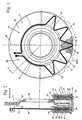
- the brake pad 10 comprises a backing plate 11 of conventional configuration and a friction material 12 secured thereto.
- the friction material 12 has a leading edge 13, a trailing edge 14, an inner peripheral edge 15 and an outer peripheral edge 16.
- a plurality of primary grooves 17 are formed into the friction material with outlet ends 18 opening onto the outer peripheral edge 16 or the trailing edge 14.
- a number of the primary grooves 17 have inlet ends opening directly onto the leading edge 13 and each of these inlet ends have mouth regions 28 of decreasing width adapted to funnel liquid flow into the grooves 17. This arrangement provides an effective means of collecting and removing bulk liquid from interengaging brake surfaces during a braking operation.
- Each of the grooves 17 have a width of 1.5 to 4 mm and an intervening land width of about 5 to 6 mm.
- each of the grooves 17 are parallel to one another. Further, it is desired that the angle ⁇ at the inlet 26 to each of the grooves 17 opening onto the inner peripheral edge 15, being the angle between the tangent to the groove curve and the tangent to the curve of the edge 15 at the inlet 26, is substantially equal for all such grooves. Moreover, this angle is also substantially equal to the same angle at the outlet ends of the grooves opening onto the outer peripheral edge 16.
- this angle may be between 20° and 40° but is preferably about 30° which is desired for optimum performance for a conventional vehicle wheel travelling initially at the allowed road speed limit i.e. 100 - 110 km/h. This corresponds to a rotor disc rpm of about 800 - 1000.
- Figures 4 and 5 show embodiments including secondary grooves 27 each intersecting the primary grooves 17 at an acute angle.
- the secondary grooves 27 may be curved as illustrated. Further, the secondary grooves 27 may pass through substantially all the friction material as shown in Figure 4 or they may be terminated at their intersection with an intermediate primary groove 17 as shown in Figure 5.
- the primary grooves opening onto the leading edge 13 of the friction material have mouth regions 28 of wider proportions which conveniently funnel liquid flow into the adjacent grooves 17.
- the radially inner wall of the groove 17 forms one wall 29 of the widened mouth region.
- the throat 30 of the intersection between the grooves 17 and 27 at the mouth region may be widened, for example by removal of the friction material indicated in dotted outline 31, so as to improve liquid flow into the two grooves 17 and 27 extending from this throat.
- Figure 6 shows a cross sectional view along lines B-B of Figures 5 and 7.
- Figure 7 shows an embodiment similar to Figure 6 except that the grooves 17 are more widely spaced towards a trailing end of the load.
- Figure 8 is a graph showing a vehicle stopping distance against brake pressure for a 2.5 tonne Toyota Land Cruiser utilising wet disc brakes as described in the foregoing specification and comparing ungrooved pads with brake pads produced according to a configuration as shown in Figure 8 hereof. It will be apparent from this comparison, that the brake system and particularly the brake pads according to the present invention out perform ungrooved pads in an otherwise similar configuration.
- the grooves of a brake pad according to the invention occupy between 20% and 40% of the braking surface area without the grooves.
Landscapes
- Engineering & Computer Science (AREA)
- General Engineering & Computer Science (AREA)
- Mechanical Engineering (AREA)
- Braking Arrangements (AREA)
Claims (11)
- Plaquette de frein comportant un matériau de friction (12) ayant une surface de freinage prévue, en fonctionnement, pour venir en contact avec un disque de rotor d'un ensemble de frein, ladite surface de freinage ayant un bord avant (13) par rapport à la rotation dudit disque de rotor, un bord arrière opposé (14), et des bords interne et externe s'étendant circonférentiellement (15, 16) rejoignant lesdits bords avant et arrière (13, 14), ledit matériau de friction (12) comportant en outre une pluralité de rainures (17) formées dans ledit matériau de friction (12), lesdites rainures (17) s'ouvrant sur ladite surface de freinage et étant inclinées depuis une extrémité avant (26) des rainures (17) vers l'arrière par rapport à une ligne radiale, au moins l'une desdites rainures (17) s'ouvrant sur le bord avant (13) de ladite surface de freinage et lesdites rainures (17) étant en outre courbées depuis leur extrémité avant (26) jusqu'à leur extrémité arrière (18) avec un côté convexe desdites rainures (17) faisant face au bord avant (13) de la surface de freinage, caractérisée en ce que chacune desdites rainures (17) a une forme arquée sur toute sa longueur et en ce que l'extrémité arrière de chacune desdites rainures sort de ladite surface de freinage soit au nivau dudit bord arrière (14) soit dudit bord externe s'étendant circonférentiellement.
- Plaquette de frein selon la revendication 1, caractérisée en ce qu'au moins certaines desdites rainures (17) ayant une extrémité avant (26) s'ouvrant sur le bord circonférentiel interne (15) de la surface de freinage et une extrémité arrière (18) s'ouvrant sur le bord externe circonférentiel (16) de la surface de freinage sont configurées de telle sorte que des lignes tangentes à la rainure au niveau de l'extrémité avant et de l'extrémité arrière (26, 18) forment des angles égaux avec les bords interne et externe circonférentiels (15, 16) de la surface de freinage.
- Plaquette de frein selon la revendication 2, caractérisée en ce que lesdits angles égaux sont compris entre 30° et 40°.
- Plaquette de frein selon l'une quelconque des revendications précédentes, caractérisée en ce que lesdites rainures (17) sont substantiellement parallèles les unes aux autres.
- Plaquette de frein selon l'une quelconque des revendications précédentes, caractérisée en ce que chacune desdites rainures (17) a une largeur comprise entre 1,5 et 4 mm.
- Plaquette de frein selon l'une quelconque des revendications précédentes, caractérisée en ce que les rainures (17) occupent entre 20% et 40% de la superficie de la surface de freinage sans lesdites rainures (17).
- Plaquette de frein selon l'une quelconque des revendications précédentes, caractérisée en ce que la largeur de la surface de freinage entre des rainures (17) adjacentes est comprise entre 5 et 6 mm.
- Plaquette de frein selon la revendication 1, caractérisée en ce qu'au moins l'une desdites rainures (17) a une portion d'embouchure agrandie (28) au niveau du bord avant (13) de ladite surface de freinage et une zone de largeur diminuant vers l'intérieur depuis ledit bord avant (13) de la surface de freinage.
- Plaquette de frein selon la revendication 8, caractérisée en ce qu'une pluralité desdites rainures (17) a des extrémités avant ouvrant sur le bord avant (13) de ladite surface de freinage, chacune desdites rainures ayant une dite portion d'embouchure élargie au niveau du bord avant (13) et une dite zone de largeur diminuant vers l'intérieur depuis ledit bord avant (13) de la surface de freinage.
- Plaquette de frein selon la revendication 8 ou 9, caractérisée en ce que certaines desdites rainures (17) ont des extrémités avant espacées vers l'intérieur depuis ledit bord interne circonférentiel de ladite surface de freinage.
- Plaquette de frein selon l'une quelconque des revendications précédentes, caractérisée en ce que lesdites rainures (17) forment des arcs de cercle.
Applications Claiming Priority (4)
| Application Number | Priority Date | Filing Date | Title |
|---|---|---|---|
| AUPM772094 | 1994-08-26 | ||
| AUPM7720A AUPM772094A0 (en) | 1994-08-26 | 1994-08-26 | Wet disc brake |
| AUPM7720/94 | 1994-08-26 | ||
| PCT/AU1995/000529 WO1996007034A1 (fr) | 1994-08-26 | 1995-08-24 | Frein a disque humide |
Publications (3)
| Publication Number | Publication Date |
|---|---|
| EP0776429A1 EP0776429A1 (fr) | 1997-06-04 |
| EP0776429A4 EP0776429A4 (fr) | 1998-09-16 |
| EP0776429B1 true EP0776429B1 (fr) | 2002-06-05 |
Family
ID=25641663
Family Applications (1)
| Application Number | Title | Priority Date | Filing Date |
|---|---|---|---|
| EP95929648A Expired - Lifetime EP0776429B1 (fr) | 1994-08-26 | 1995-08-24 | Frein a disque humide |
Country Status (12)
| Country | Link |
|---|---|
| US (1) | US6119828A (fr) |
| EP (1) | EP0776429B1 (fr) |
| JP (1) | JPH10506174A (fr) |
| KR (1) | KR100348373B1 (fr) |
| AT (1) | ATE218681T1 (fr) |
| AU (1) | AU710572B2 (fr) |
| BR (1) | BR9508882A (fr) |
| CA (1) | CA2198592C (fr) |
| DE (1) | DE69526942T2 (fr) |
| DK (1) | DK0776429T3 (fr) |
| NZ (1) | NZ291717A (fr) |
| WO (1) | WO1996007034A1 (fr) |
Families Citing this family (38)
| Publication number | Priority date | Publication date | Assignee | Title |
|---|---|---|---|---|
| EP0985841B1 (fr) * | 1998-09-11 | 2003-02-26 | Brembo S.p.A. | Disque de frein haute performance à cannelures de drainage et de contrôle optique de l'usure |
| CN1454297A (zh) * | 2000-08-01 | 2003-11-05 | 安全有效技术国际有限公司 | 湿式制动系统 |
| AU1843101A (en) | 2000-08-01 | 2002-02-13 | Safe Effect Technologies Inter | Brake plate |
| RU2207457C2 (ru) * | 2001-05-14 | 2003-06-27 | Оао "Тиир" | Фрикционный диск |
| US20080047786A1 (en) * | 2003-06-06 | 2008-02-28 | Safe Effect Pty Ltd | Fluid cooled wet brake system |
| KR100534846B1 (ko) * | 2003-08-30 | 2005-12-09 | 현대자동차주식회사 | 디스크 브레이크의 건조장치 |
| DE10342271B4 (de) * | 2003-09-12 | 2014-07-10 | Zf Friedrichshafen Ag | Reibbelag-Lamelle |
| DE102006031035A1 (de) * | 2006-07-05 | 2008-01-10 | Zf Friedrichshafen Ag | Reibscheibe für eine nasslaufende Kupplung für ein Fahrzeug |
| WO2008103759A1 (fr) | 2007-02-20 | 2008-08-28 | Tech M3, Inc. | Disques de frein en matériau composite et procédé de revêtement |
| EP2122004B1 (fr) * | 2007-02-20 | 2013-01-30 | Tech M3, Inc. | Revêtement résistant à l'usure pour disques de frein avec aspect de surface unique et procédés de revêtement |
| US8893863B2 (en) * | 2007-08-22 | 2014-11-25 | Tech M3, Inc. | Reduction of particulate emissions from vehicle braking systems |
| US20110048871A1 (en) * | 2007-08-22 | 2011-03-03 | Meckel Nathan K | Brake rotors, disk assemblies, and other components |
| CN101836006B (zh) | 2007-08-22 | 2013-04-24 | M3技术有限公司 | 制动盘及其制造方法 |
| US20090071766A1 (en) * | 2007-09-13 | 2009-03-19 | Akebono Corporation (North America) | Brake pad assembly with wide slots for the reduction of noise |
| RU2454576C2 (ru) * | 2008-01-24 | 2012-06-27 | Троя Кэпитал Групп Корп. | Колодка дискового тормоза автомобиля |
| US8146719B2 (en) * | 2008-04-25 | 2012-04-03 | GM Global Technology Operations LLC | Disk brake friction surfaces with tunable indent patterns for minimizing brake pad radial taper wear |
| JP3149594U (ja) * | 2009-01-22 | 2009-04-02 | 株式会社ダイナックス | 湿式摩擦板および湿式摩擦係合装置 |
| KR101137583B1 (ko) * | 2010-02-17 | 2012-04-19 | 동양물산기업 주식회사 | 유압 습식 브레이크 |
| EP2383485B1 (fr) * | 2010-04-30 | 2013-02-13 | Brembo SGL Carbon Ceramic Brakes GmbH | Procédé et dispositif pour générer une document d'ontologie |
| JP5341856B2 (ja) * | 2010-10-04 | 2013-11-13 | 日立建機株式会社 | 湿式ブレーキ装置 |
| RU2461749C1 (ru) * | 2011-03-31 | 2012-09-20 | Общество с ограниченной ответственностью "ТРВ Аутомотив" (ООО "ТРВ Аутомотив") | Фрикционное изделие |
| RU2464460C1 (ru) * | 2011-03-31 | 2012-10-20 | Общество с ограниченной ответственностью "ТРВ Аутомотив" (ООО "ТРВ Аутомотив") | Фрикционное изделие |
| DE102011106009A1 (de) * | 2011-06-30 | 2013-01-03 | Borgwarner Inc. | Verfahren zur Erzeugung eines Vertiefungsmusters in der Reibfläche eines Reibteils und Reibteil für eine reibschlüssig arbeitende Einrichtung mit einem solchen Vertiefungsmuster |
| US10012279B2 (en) | 2013-03-15 | 2018-07-03 | Tech M3, Inc. | Braking systems incorporating wear and corrosion resistant rotors |
| WO2014145227A1 (fr) | 2013-03-15 | 2014-09-18 | Tech M3, Inc. | Systèmes de freinage résistants à l'usure |
| JP5751288B2 (ja) * | 2013-06-27 | 2015-07-22 | トヨタ自動車株式会社 | ディスクブレーキ装置、及び、一対のブレーキパッド |
| RU2551051C2 (ru) * | 2013-08-29 | 2015-05-20 | Открытое акционерное общество "Завод фрикционных и термостойких материалов" | Тормозная накладка для дискового тормоза железнодорожного подвижного состава |
| CA2949680C (fr) | 2014-05-19 | 2023-01-10 | Tech M3, Inc. | Rotor de frein a inserts de surface de travail |
| WO2015192002A1 (fr) * | 2014-06-13 | 2015-12-17 | Federal-Mogul Motorparts Corporation | Plaquette de frein à disque pour un véhicule |
| KR101955136B1 (ko) * | 2015-01-13 | 2019-03-06 | 가부시키가이샤 히타치세이사쿠쇼 | 브레이크 장치 및 엘리베이터 시스템 |
| DE102015108049A1 (de) * | 2015-05-21 | 2016-11-24 | Tmd Friction Services Gmbh | Bremsbelag bei Scheibenbremsen, insbesondere von Fahrzeugen, mit Nutausbildung im Reibbelag |
| US9976610B2 (en) | 2015-09-03 | 2018-05-22 | Bendix Spicer Foundation Brake Llc | Wear optimized pad design |
| US9605721B1 (en) * | 2015-09-03 | 2017-03-28 | Bendix Spicer Foundation Brake Llc | Wear optimized pad design |
| US10962072B2 (en) * | 2015-12-17 | 2021-03-30 | Federal-Mogul Motorparts Llc | Friction lining and brake pad for a braking system |
| RU2652419C1 (ru) * | 2016-12-14 | 2018-04-26 | Открытое акционерное общество "Уральский завод авто-текстильных изделий" (ОАО "УралАТИ") | Накладка тормозная дискового тормоза железнодорожного транспортного средства |
| US10724587B2 (en) | 2017-06-28 | 2020-07-28 | Federal-Mogul Motorparts Llc | Disc brake pad for a vehicle |
| KR102587909B1 (ko) * | 2019-05-17 | 2023-10-11 | 현대자동차주식회사 | 마찰플레이트 |
| DE102022202856B4 (de) | 2021-03-26 | 2023-09-28 | Hl Mando Corporation | Bremsklotz |
Family Cites Families (27)
| Publication number | Priority date | Publication date | Assignee | Title |
|---|---|---|---|---|
| FR956620A (fr) * | 1950-02-02 | |||
| US2924308A (en) * | 1956-01-23 | 1960-02-09 | Gen Motors Corp | Brake cooling system |
| GB1025881A (en) * | 1961-04-12 | 1966-04-14 | Girling Ltd | Improvements in disc brakes |
| DE1425202A1 (de) * | 1961-09-12 | 1968-10-24 | Celestino Benini | Backenbremse,insbesondere Fahr?eugbremse |
| US3303911A (en) * | 1964-12-07 | 1967-02-14 | Gen Motors Corp | Fluid cooled brake mechanism |
| FR1527763A (fr) * | 1966-10-06 | 1968-06-07 | Hispano Suiza Lallemant Soc | Perfectionnements apportés aux dispositifs à disques de friction, notamment aux freins |
| US3405786A (en) * | 1967-06-09 | 1968-10-15 | Robert W. Goode | Fluid pressure control for brake mechanism with cooling means |
| US3623577A (en) * | 1969-11-13 | 1971-11-30 | Kelsey Hayes Co | Corrugated rotor for disk brakes |
| DE2539557A1 (de) * | 1975-09-05 | 1977-03-10 | Messerschmitt Boelkow Blohm | Reibungsbremse mit bremsbacken |
| US4011930A (en) * | 1976-04-12 | 1977-03-15 | International Harvester Company | Means to present lubricating and cooling fluid to friction material in a wet brake system |
| AU522501B2 (en) * | 1978-04-08 | 1982-06-10 | Lucas Industries Public Limited Company | Friction pad assemblies for rail vehicle brakes |
| US4287978A (en) * | 1979-07-25 | 1981-09-08 | General Motors Corporation | Annular friction disc with radial grooving |
| US4501347A (en) * | 1982-09-15 | 1985-02-26 | Abex Corporation | Segmented disc brake pad |
| IN161356B (fr) * | 1983-06-11 | 1987-11-14 | Lucas Ind Plc | |
| US4828089A (en) * | 1985-05-07 | 1989-05-09 | Eaton Corporation | Brake/clutch with direct liquid cooling |
| JPH0730346B2 (ja) * | 1986-09-08 | 1995-04-05 | 出光興産株式会社 | 潤滑油組成物 |
| US5064546A (en) * | 1987-04-11 | 1991-11-12 | Idemitsu Kosan Co., Ltd. | Lubricating oil composition |
| GB8717877D0 (en) * | 1987-07-28 | 1987-09-03 | Lucas Ind Plc | Vehicle disc brakes |
| FR2640337A1 (fr) * | 1988-12-09 | 1990-06-15 | Abex Equipements Sa | Element en materiau de friction pour frein de vehicule |
| DE9003854U1 (de) * | 1990-04-03 | 1990-06-13 | Becorit-Gesellschaft W. Beckmann Gmbh & Co Kg, 4350 Recklinghausen | Parzellierter Bremsbelag für Scheibenbremsen |
| DE4036908A1 (de) * | 1990-11-20 | 1992-05-21 | Ruetgers Pagid Ag | Nutausbildung |
| FR2681925B1 (fr) * | 1991-10-01 | 1997-09-05 | Flertex Sa | Plaquette de frein a disque pour chemin de fer. |
| ATE175477T1 (de) * | 1991-10-11 | 1999-01-15 | Francis Edward Parsons | Nass-scheibenbremse |
| US5816901A (en) * | 1993-04-09 | 1998-10-06 | Sirany; Dallas R. | Method of resurfacing a vehicles's braking rotors and drums |
| GB2278309A (en) * | 1993-05-25 | 1994-11-30 | T & N Technology Ltd | Friction element |
| JPH08277866A (ja) * | 1995-04-04 | 1996-10-22 | Akebono Brake Ind Co Ltd | ブレーキパッド |
| FR2733290B1 (fr) * | 1995-04-24 | 1997-06-20 | Flertex Sa | Plaquette de frein a disque pour chemin de fer |
-
1995
- 1995-08-24 EP EP95929648A patent/EP0776429B1/fr not_active Expired - Lifetime
- 1995-08-24 KR KR1019970701398A patent/KR100348373B1/ko not_active Expired - Fee Related
- 1995-08-24 US US08/793,492 patent/US6119828A/en not_active Expired - Lifetime
- 1995-08-24 BR BR9508882A patent/BR9508882A/pt not_active IP Right Cessation
- 1995-08-24 AU AU33338/95A patent/AU710572B2/en not_active Ceased
- 1995-08-24 JP JP8508342A patent/JPH10506174A/ja active Pending
- 1995-08-24 DE DE69526942T patent/DE69526942T2/de not_active Expired - Lifetime
- 1995-08-24 CA CA002198592A patent/CA2198592C/fr not_active Expired - Fee Related
- 1995-08-24 WO PCT/AU1995/000529 patent/WO1996007034A1/fr not_active Ceased
- 1995-08-24 DK DK95929648T patent/DK0776429T3/da active
- 1995-08-24 AT AT95929648T patent/ATE218681T1/de not_active IP Right Cessation
- 1995-08-24 NZ NZ291717A patent/NZ291717A/xx unknown
Also Published As
| Publication number | Publication date |
|---|---|
| ATE218681T1 (de) | 2002-06-15 |
| KR970705709A (ko) | 1997-10-09 |
| AU710572B2 (en) | 1999-09-23 |
| HK1014381A1 (en) | 1999-09-24 |
| DK0776429T3 (da) | 2002-10-07 |
| DE69526942T2 (de) | 2003-02-20 |
| JPH10506174A (ja) | 1998-06-16 |
| KR100348373B1 (ko) | 2002-11-22 |
| CA2198592C (fr) | 2009-02-17 |
| AU3333895A (en) | 1996-03-22 |
| EP0776429A4 (fr) | 1998-09-16 |
| EP0776429A1 (fr) | 1997-06-04 |
| CA2198592A1 (fr) | 1996-03-07 |
| WO1996007034A1 (fr) | 1996-03-07 |
| DE69526942D1 (de) | 2002-07-11 |
| BR9508882A (pt) | 1997-12-30 |
| NZ291717A (en) | 1999-05-28 |
| US6119828A (en) | 2000-09-19 |
Similar Documents
| Publication | Publication Date | Title |
|---|---|---|
| US6119828A (en) | Wet disc brake | |
| US6186285B1 (en) | Wet disc brake | |
| JP5292401B2 (ja) | 摩擦面にジグザク状または波状の周方向の溝を備える摩擦部 | |
| DE69025016T2 (de) | Energieabsorbierende Vorrichtung | |
| CN1081762C (zh) | 用于车辆的制动装置 | |
| EP0669219B1 (fr) | Essieu moteur pour véhicules, comportant un circuit de lubrification | |
| US4961485A (en) | Oil circulation in wheel head transmission | |
| US10738850B2 (en) | Disc brake calliper body | |
| JPH08505685A (ja) | エネルギ吸収システム | |
| US20110011795A1 (en) | Fluid pressure driven centrifuge apparatus | |
| KR20210143211A (ko) | 라이닝의 그루브에 원심 흡입이 있는 제동 시스템 | |
| AU738677B2 (en) | Wet disc brake | |
| EP0307079A1 (fr) | Frein à disque avec refroidissement à liquide pour véhicules | |
| WO1995012765A2 (fr) | Frein a disque annulaire refroidi par le flux d'air | |
| HK1014381B (en) | Wet disc brake | |
| TW200300485A (en) | An oil wiper ring divided into segments | |
| WO1995008727A1 (fr) | Rotor de frein a disque | |
| US20020162710A1 (en) | Friction engagement device | |
| RU2148512C1 (ru) | Приводной агрегат, в частности для автомобиля | |
| GB2116654A (en) | A disc for a disc brake | |
| US5439081A (en) | Compressed coolant hydraulic brake rotor | |
| RU2169674C2 (ru) | Приводной агрегат в частности для автомобиля с гидродинамическим тормозом-замедлителем | |
| US4865168A (en) | Vehicle disc brakes of the liquid cooled type | |
| CN104912841B (zh) | 离心压缩机及包含该离心压缩机的制冷设备 | |
| CN1802520A (zh) | 流体冷却的湿式制动系统 |
Legal Events
| Date | Code | Title | Description |
|---|---|---|---|
| PUAI | Public reference made under article 153(3) epc to a published international application that has entered the european phase |
Free format text: ORIGINAL CODE: 0009012 |
|
| 17P | Request for examination filed |
Effective date: 19970326 |
|
| AK | Designated contracting states |
Kind code of ref document: A1 Designated state(s): AT BE CH DE DK ES FR GB GR IE IT LI LU MC NL PT SE |
|
| A4 | Supplementary search report drawn up and despatched |
Effective date: 19980730 |
|
| AK | Designated contracting states |
Kind code of ref document: A4 Designated state(s): AT BE CH DE DK ES FR GB GR IE IT LI LU MC NL PT SE |
|
| RA4 | Supplementary search report drawn up and despatched (corrected) |
Effective date: 19980902 |
|
| RAP1 | Party data changed (applicant data changed or rights of an application transferred) |
Owner name: BRAKE TECHNOLOGIES PTY. LTD. |
|
| RIN1 | Information on inventor provided before grant (corrected) |
Inventor name: BRAKE TECHNOLOGIES PTY. LTD. |
|
| 17Q | First examination report despatched |
Effective date: 19991117 |
|
| GRAG | Despatch of communication of intention to grant |
Free format text: ORIGINAL CODE: EPIDOS AGRA |
|
| GRAG | Despatch of communication of intention to grant |
Free format text: ORIGINAL CODE: EPIDOS AGRA |
|
| GRAG | Despatch of communication of intention to grant |
Free format text: ORIGINAL CODE: EPIDOS AGRA |
|
| GRAH | Despatch of communication of intention to grant a patent |
Free format text: ORIGINAL CODE: EPIDOS IGRA |
|
| GRAH | Despatch of communication of intention to grant a patent |
Free format text: ORIGINAL CODE: EPIDOS IGRA |
|
| GRAA | (expected) grant |
Free format text: ORIGINAL CODE: 0009210 |
|
| RIN1 | Information on inventor provided before grant (corrected) |
Inventor name: PARSONS, FRANCIS EDWARD |
|
| AK | Designated contracting states |
Kind code of ref document: B1 Designated state(s): AT BE CH DE DK ES FR GB GR IE IT LI LU MC NL PT SE |
|
| REF | Corresponds to: |
Ref document number: 218681 Country of ref document: AT Date of ref document: 20020615 Kind code of ref document: T |
|
| REG | Reference to a national code |
Ref country code: GB Ref legal event code: FG4D |
|
| REG | Reference to a national code |
Ref country code: CH Ref legal event code: EP |
|
| REG | Reference to a national code |
Ref country code: IE Ref legal event code: FG4D |
|
| REF | Corresponds to: |
Ref document number: 69526942 Country of ref document: DE Date of ref document: 20020711 |
|
| PG25 | Lapsed in a contracting state [announced via postgrant information from national office to epo] |
Ref country code: LU Free format text: LAPSE BECAUSE OF NON-PAYMENT OF DUE FEES Effective date: 20020824 |
|
| REG | Reference to a national code |
Ref country code: DK Ref legal event code: T3 |
|
| REG | Reference to a national code |
Ref country code: CH Ref legal event code: NV Representative=s name: A. BRAUN, BRAUN, HERITIER, ESCHMANN AG PATENTANWAE |
|
| REG | Reference to a national code |
Ref country code: GR Ref legal event code: EP Ref document number: 20020402978 Country of ref document: GR |
|
| ET | Fr: translation filed | ||
| REG | Reference to a national code |
Ref country code: PT Ref legal event code: SC4A Free format text: AVAILABILITY OF NATIONAL TRANSLATION Effective date: 20020904 |
|
| REG | Reference to a national code |
Ref country code: ES Ref legal event code: FG2A Ref document number: 2179883 Country of ref document: ES Kind code of ref document: T3 |
|
| PG25 | Lapsed in a contracting state [announced via postgrant information from national office to epo] |
Ref country code: MC Free format text: LAPSE BECAUSE OF NON-PAYMENT OF DUE FEES Effective date: 20030301 |
|
| PLBE | No opposition filed within time limit |
Free format text: ORIGINAL CODE: 0009261 |
|
| STAA | Information on the status of an ep patent application or granted ep patent |
Free format text: STATUS: NO OPPOSITION FILED WITHIN TIME LIMIT |
|
| 26N | No opposition filed |
Effective date: 20030306 |
|
| REG | Reference to a national code |
Ref country code: PT Ref legal event code: NF4A Free format text: RESTITUTIO IN INTEGRUM Effective date: 20040301 |
|
| PGFP | Annual fee paid to national office [announced via postgrant information from national office to epo] |
Ref country code: NL Payment date: 20040823 Year of fee payment: 10 |
|
| PGFP | Annual fee paid to national office [announced via postgrant information from national office to epo] |
Ref country code: PT Payment date: 20040824 Year of fee payment: 10 |
|
| PGFP | Annual fee paid to national office [announced via postgrant information from national office to epo] |
Ref country code: SE Payment date: 20040826 Year of fee payment: 10 Ref country code: AT Payment date: 20040826 Year of fee payment: 10 |
|
| PGFP | Annual fee paid to national office [announced via postgrant information from national office to epo] |
Ref country code: IE Payment date: 20040827 Year of fee payment: 10 Ref country code: DK Payment date: 20040827 Year of fee payment: 10 Ref country code: CH Payment date: 20040827 Year of fee payment: 10 |
|
| PGFP | Annual fee paid to national office [announced via postgrant information from national office to epo] |
Ref country code: GR Payment date: 20040831 Year of fee payment: 10 |
|
| PGFP | Annual fee paid to national office [announced via postgrant information from national office to epo] |
Ref country code: BE Payment date: 20041020 Year of fee payment: 10 |
|
| PG25 | Lapsed in a contracting state [announced via postgrant information from national office to epo] |
Ref country code: IE Free format text: LAPSE BECAUSE OF NON-PAYMENT OF DUE FEES Effective date: 20050824 Ref country code: AT Free format text: LAPSE BECAUSE OF NON-PAYMENT OF DUE FEES Effective date: 20050824 |
|
| PG25 | Lapsed in a contracting state [announced via postgrant information from national office to epo] |
Ref country code: SE Free format text: LAPSE BECAUSE OF NON-PAYMENT OF DUE FEES Effective date: 20050825 |
|
| PG25 | Lapsed in a contracting state [announced via postgrant information from national office to epo] |
Ref country code: LI Free format text: LAPSE BECAUSE OF NON-PAYMENT OF DUE FEES Effective date: 20050831 Ref country code: DK Free format text: LAPSE BECAUSE OF NON-PAYMENT OF DUE FEES Effective date: 20050831 Ref country code: CH Free format text: LAPSE BECAUSE OF NON-PAYMENT OF DUE FEES Effective date: 20050831 Ref country code: BE Free format text: LAPSE BECAUSE OF NON-PAYMENT OF DUE FEES Effective date: 20050831 |
|
| PGFP | Annual fee paid to national office [announced via postgrant information from national office to epo] |
Ref country code: ES Payment date: 20050920 Year of fee payment: 11 |
|
| PG25 | Lapsed in a contracting state [announced via postgrant information from national office to epo] |
Ref country code: PT Free format text: LAPSE BECAUSE OF NON-PAYMENT OF DUE FEES Effective date: 20060224 |
|
| PG25 | Lapsed in a contracting state [announced via postgrant information from national office to epo] |
Ref country code: NL Free format text: LAPSE BECAUSE OF NON-PAYMENT OF DUE FEES Effective date: 20060301 |
|
| PG25 | Lapsed in a contracting state [announced via postgrant information from national office to epo] |
Ref country code: GR Free format text: LAPSE BECAUSE OF NON-PAYMENT OF DUE FEES Effective date: 20060302 |
|
| REG | Reference to a national code |
Ref country code: CH Ref legal event code: PL |
|
| REG | Reference to a national code |
Ref country code: DK Ref legal event code: EBP |
|
| EUG | Se: european patent has lapsed | ||
| NLV4 | Nl: lapsed or anulled due to non-payment of the annual fee |
Effective date: 20060301 |
|
| REG | Reference to a national code |
Ref country code: IE Ref legal event code: MM4A |
|
| REG | Reference to a national code |
Ref country code: ES Ref legal event code: FD2A Effective date: 20060825 |
|
| BERE | Be: lapsed |
Owner name: *BRAKE TECHNOLOGIES PTY. LTD Effective date: 20050831 |
|
| PGFP | Annual fee paid to national office [announced via postgrant information from national office to epo] |
Ref country code: GB Payment date: 20070822 Year of fee payment: 13 |
|
| PG25 | Lapsed in a contracting state [announced via postgrant information from national office to epo] |
Ref country code: ES Free format text: LAPSE BECAUSE OF NON-PAYMENT OF DUE FEES Effective date: 20060825 |
|
| PGFP | Annual fee paid to national office [announced via postgrant information from national office to epo] |
Ref country code: IT Payment date: 20070830 Year of fee payment: 13 |
|
| PGFP | Annual fee paid to national office [announced via postgrant information from national office to epo] |
Ref country code: FR Payment date: 20070828 Year of fee payment: 13 |
|
| GBPC | Gb: european patent ceased through non-payment of renewal fee |
Effective date: 20080824 |
|
| REG | Reference to a national code |
Ref country code: FR Ref legal event code: ST Effective date: 20090430 |
|
| PG25 | Lapsed in a contracting state [announced via postgrant information from national office to epo] |
Ref country code: IT Free format text: LAPSE BECAUSE OF NON-PAYMENT OF DUE FEES Effective date: 20080824 Ref country code: FR Free format text: LAPSE BECAUSE OF NON-PAYMENT OF DUE FEES Effective date: 20080901 |
|
| PG25 | Lapsed in a contracting state [announced via postgrant information from national office to epo] |
Ref country code: GB Free format text: LAPSE BECAUSE OF NON-PAYMENT OF DUE FEES Effective date: 20080824 |
|
| PGFP | Annual fee paid to national office [announced via postgrant information from national office to epo] |
Ref country code: DE Payment date: 20130930 Year of fee payment: 19 |
|
| REG | Reference to a national code |
Ref country code: DE Ref legal event code: R119 Ref document number: 69526942 Country of ref document: DE |
|
| REG | Reference to a national code |
Ref country code: DE Ref legal event code: R119 Ref document number: 69526942 Country of ref document: DE Effective date: 20150303 |
|
| PG25 | Lapsed in a contracting state [announced via postgrant information from national office to epo] |
Ref country code: DE Free format text: LAPSE BECAUSE OF NON-PAYMENT OF DUE FEES Effective date: 20150303 |