EP0776720A1 - Machine-outil rotative à broches multiples - Google Patents
Machine-outil rotative à broches multiples Download PDFInfo
- Publication number
- EP0776720A1 EP0776720A1 EP96118989A EP96118989A EP0776720A1 EP 0776720 A1 EP0776720 A1 EP 0776720A1 EP 96118989 A EP96118989 A EP 96118989A EP 96118989 A EP96118989 A EP 96118989A EP 0776720 A1 EP0776720 A1 EP 0776720A1
- Authority
- EP
- European Patent Office
- Prior art keywords
- machine tool
- tool
- carousel machine
- tool according
- processing unit
- Prior art date
- Legal status (The legal status is an assumption and is not a legal conclusion. Google has not performed a legal analysis and makes no representation as to the accuracy of the status listed.)
- Withdrawn
Links
- 238000012545 processing Methods 0.000 claims abstract description 42
- 238000003754 machining Methods 0.000 claims description 18
- 238000010276 construction Methods 0.000 abstract description 6
- 230000033001 locomotion Effects 0.000 description 15
- 238000006073 displacement reaction Methods 0.000 description 5
- 238000013461 design Methods 0.000 description 4
- 238000005553 drilling Methods 0.000 description 4
- 230000007613 environmental effect Effects 0.000 description 3
- 238000012423 maintenance Methods 0.000 description 3
- 230000008859 change Effects 0.000 description 2
- 238000004519 manufacturing process Methods 0.000 description 2
- 238000000034 method Methods 0.000 description 2
- 230000009471 action Effects 0.000 description 1
- 230000008901 benefit Effects 0.000 description 1
- 230000005540 biological transmission Effects 0.000 description 1
- 238000009434 installation Methods 0.000 description 1
- 230000004048 modification Effects 0.000 description 1
- 238000012986 modification Methods 0.000 description 1
- 230000008569 process Effects 0.000 description 1
Images


Classifications
-
- B—PERFORMING OPERATIONS; TRANSPORTING
- B23—MACHINE TOOLS; METAL-WORKING NOT OTHERWISE PROVIDED FOR
- B23Q—DETAILS, COMPONENTS, OR ACCESSORIES FOR MACHINE TOOLS, e.g. ARRANGEMENTS FOR COPYING OR CONTROLLING; MACHINE TOOLS IN GENERAL CHARACTERISED BY THE CONSTRUCTION OF PARTICULAR DETAILS OR COMPONENTS; COMBINATIONS OR ASSOCIATIONS OF METAL-WORKING MACHINES, NOT DIRECTED TO A PARTICULAR RESULT
- B23Q1/00—Members which are comprised in the general build-up of a form of machine, particularly relatively large fixed members
- B23Q1/25—Movable or adjustable work or tool supports
- B23Q1/44—Movable or adjustable work or tool supports using particular mechanisms
- B23Q1/50—Movable or adjustable work or tool supports using particular mechanisms with rotating pairs only, the rotating pairs being the first two elements of the mechanism
- B23Q1/54—Movable or adjustable work or tool supports using particular mechanisms with rotating pairs only, the rotating pairs being the first two elements of the mechanism two rotating pairs only
- B23Q1/5468—Movable or adjustable work or tool supports using particular mechanisms with rotating pairs only, the rotating pairs being the first two elements of the mechanism two rotating pairs only a single rotating pair followed parallelly by a single rotating pair
-
- B—PERFORMING OPERATIONS; TRANSPORTING
- B23—MACHINE TOOLS; METAL-WORKING NOT OTHERWISE PROVIDED FOR
- B23Q—DETAILS, COMPONENTS, OR ACCESSORIES FOR MACHINE TOOLS, e.g. ARRANGEMENTS FOR COPYING OR CONTROLLING; MACHINE TOOLS IN GENERAL CHARACTERISED BY THE CONSTRUCTION OF PARTICULAR DETAILS OR COMPONENTS; COMBINATIONS OR ASSOCIATIONS OF METAL-WORKING MACHINES, NOT DIRECTED TO A PARTICULAR RESULT
- B23Q39/00—Metal-working machines incorporating a plurality of sub-assemblies, each capable of performing a metal-working operation
- B23Q39/04—Metal-working machines incorporating a plurality of sub-assemblies, each capable of performing a metal-working operation the sub-assemblies being arranged to operate simultaneously at different stations, e.g. with an annular work-table moved in steps
- B23Q39/042—Metal-working machines incorporating a plurality of sub-assemblies, each capable of performing a metal-working operation the sub-assemblies being arranged to operate simultaneously at different stations, e.g. with an annular work-table moved in steps with circular arrangement of the sub-assemblies
Definitions
- the invention relates to a carousel machine tool according to the preamble of patent claim 1.
- Such a machine is disclosed in DE 39 41 480 C2. It comprises a cage-like frame made up of a plurality of C-shaped stands which are arranged in a star shape around a central vertical axis. Around the vertical axis, a cyclically rotationally drivable holding device is provided with a plurality of receptacles in which the workpieces to be machined are clamped. The number of shots corresponds to the number of C-shaped stands.
- Three processing units are provided on each stand, namely an upper, a lower and a middle unit which is mounted somewhat radially outside. The units can simultaneously process a workpiece clamped in the associated holder, from above, from below and from the outside on the radial side.
- Each holder together with the processing units of an associated stand forms a work station including a loading and unloading station.
- All processing units can be equipped with a slide assembly that is constructed in such a way that the tool that is intended for one work step can be adjusted in the three coordinates X, Y and Z of a right-angled coordinate system is. It is possible to operate the carriage assembly in the three coordinates mentioned under program control.
- Such machine tools have proven themselves well for mass production. Because a large number of workpieces can be produced at reasonable costs at a given time. The disadvantage is the relatively large construction of the machines, which therefore require a correspondingly large installation space.
- the object of the invention is to improve a carousel machine tool of the type mentioned in the introduction, which is constructed in a space-saving manner and makes it possible, in addition to large and small and smallest series of workpieces, to also produce relatively large dimensions economically. In addition, it should be possible to install high-performance drive motors.
- This construction of the tool carrier considerably simplifies the construction of the slide of the respective machining unit, in particular in that it does not have a displacement structure in the tangential direction of movement, ie in the direction the X coordinate. Nevertheless, it is achieved that the tool carrier and thus the tool eccentrically clamped therein has a relatively large adjustment path available in the tangential direction. Thus, workpieces can also be machined that have a relatively large dimension, although the frame structure offers relatively little space in the tangential direction due to the space-saving or compact design of the carousel machine tool according to the invention. Overall, a carousel machine tool that is significantly reduced in its outer dimensions is achieved with at least the same production output in comparison with known machines. Furthermore, it is possible to install a very powerful electric motor for driving the tool of the tool carrier, e.g. B. with a power of 4.0 kW, because the simplified structure of the processing unit also provides more space for its assembly.
- a very powerful electric motor for driving the tool of the tool carrier e.g. B.
- a preferred embodiment of the carousel machine tool according to the invention is that the tool carrier is connected to a drive pinion which is in engagement with a rack which can be driven back and forth.
- the rack can be driven with the aid of a hydraulic cylinder unit, which is provided with an integrated position-sensing position measuring device.
- Such a drive is insensitive to the environmental influences of the machine tool.
- the tool carrier can be arranged on a slide which can be driven in the direction of the radial Y coordinate.
- This carriage structure is in turn arranged on a basic structure which can be driven in the direction of the Z coordinate.
- a hydraulic cylinder unit with an integrated position-sensing position measuring device can in turn serve as the drive for the slide or the basic structure. This results in a simplified structure of the respective machining unit, which is insensitive to the environmental influences of the machine tool.
- the radially working processing unit can be pivoted laterally about an additional vertical axis in the horizontal direction and can be fixed in the working position. This ensures that all tools within a workstation, for. B. are easily and quickly accessible for maintenance and tool change.
- the receptacles of the workpiece holding device can each be equipped with a removable clamping pallet. It is thus possible to mount the workpieces to be machined on the respective clamping pallet outside the machine tools, which in turn can then be quickly and easily mounted on the respective receptacle of the cyclically driven workpiece holding device. This shortens the set-up time for clamping the workpiece in the machine tool.
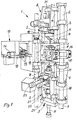
- the basic structure of the carousel machine tool, generally designated 1, is known and is therefore only briefly explained in this regard.
- the machine frame comprises, for example, six vertical columns 2 which are circumferentially evenly spaced from one another and are held in position by means of an upper connecting structure 3 and a lower connecting structure 4.
- a central workpiece holding device which can be driven intermittently and rotatably about an upright axis, is arranged in a known manner, for example a so-called rotary table, which has a plurality of receptacles for workpieces to be machined in the rest position.
- the workpiece holding device or the turntable has, for example, five receptacles 6, each receptacle 6 carrying a workpiece 7. With six recordings, there are five processing stations, each of which is assigned at least one processing unit and usually a loading and unloading station.
- the work station shown is equipped with three processing units, namely an upper unit 8, a lower unit 9 and a middle unit 10.
- Each processing unit is equipped with an adjustable tool holder 11 provided, which is equipped with at least one tool 12, for example a drill.
- the tool carrier of the processing unit 10 is equipped with a plurality of drills 13, which are arranged on a circle in order to drill several holes at the same time.
- the tool holder 11 and thus the tool 12 clamped therein can be set in a maximum of three spatial coordinates X, Y and Z, as will become clear.
- the tool carrier 11 of the upper processing unit 8 and the lower processing unit 9 can be set in the three coordinates mentioned, while the central processing unit 10 can only be set in one coordinate, namely in the radial direction, while the tool carrier is constantly on the two other coordinates is set.
- the machining unit 10 or its tool carrier can be adjustable in three coordinates, in accordance with the tool carrier of the other two units 8 and 9.
- FIG. 1 further shows that the middle processing unit 10 is pivotally mounted on a column 2, as can also be seen in Figures 6 and 7.
- FIGS. 1 and 7 show the middle unit 10 in the swung-out position, while the unit 10 is shown in FIG. 6 in the fixing position.
- This way of attaching the unit 10 enables all tools of all units 8, 9 and 10 to be quickly and easily accessible for maintenance purposes and tool change when the unit 10 is pivoted out. This also results in short downtimes of the machine 1 when a tool has to be changed or maintenance has to be carried out on the machine.
- the central, radially working processing unit 10 there is a machine 1 on the frame, for example on the column 2 arranged, pivotable bracket 14 with locking means 15 and a projection 16 formed on the processing unit are provided, which engages in the bracket 14, as can be clearly seen from FIG. 6.
- the locking means consist, for example, of a single screw 15 which is pressed against the projection 16 and thus fixes the unit 10. This construction enables the unit 10 to be released and fixed quickly, ie in a time-saving manner.
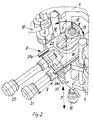
- FIG. 2 which shows the lower processing unit 9
- the movement sequences for setting and actuating the tool 12 are now explained in more detail.
- the movements described also apply analogously to the upper machining unit 8 and the middle machining unit 10. While the upper and lower units are machining in the vertical direction, the machining of the middle unit 10 takes place in the radial direction, namely radially to the workpiece holding device 5, on which the workpiece 7 to be machined is clamped.
- the tool 12 is set in the three coordinates named X, Y and Z; the radial setting direction, the Y coordinate, the tangential setting direction, the X coordinate and the vertical setting direction, the Z coordinate. While the settings in the Y and Z directions are made only in a straight line according to the double arrows shown, the exact setting in the direction of the X coordinate is made up of two partial movements.
- the tool carrier 11 is mounted so as to be drivable about a pivot axis 17 to which the tool 12 is mounted eccentrically according to FIG. 2.
- the tool 12 performs a circular arc movement about the axis 17 in accordance with the double arrow shown.
- the movement of the tool 12 takes place in accordance with the Y coordinate, so that ultimately an adjustment of the tool 12 corresponds to a straight X-adjustment direction.
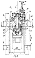
- Each processing unit 8, 9 and 10 is slidably mounted on two columns 18 located opposite one another, which in turn are arranged in a stationary manner on the frame structures 3 and 4 of the machine 1.
- a hydraulic cylinder unit 19 For setting and working movement in the direction of the Z coordinate, a hydraulic cylinder unit 19 is provided, which is provided with a position measuring device (not shown) that can be queried for position.
- a position measuring device (not shown) that can be queried for position.
- Such an electronically interrogated displacement measuring device can preferably be provided within the unit 19, so that it is protected against environmental influences of the machine and safe operation of the unit 19 is ensured.
- the tool carrier 11 is movably mounted on the slide 20 about the pivot axis 17, which can be moved in the direction of the Y coordinate by means of a further hydraulic cylinder unit 21.
- the carriage 20 is slidably mounted on rails 20a of a base structure 22 of the processing unit 9.
- the hydraulic cylinder unit 21 is also equipped with a position measuring device that can be queried.
- a still further hydraulic cylinder unit 23 with an integrated displacement measuring device is attached to the base structure 22 of the unit 9 and causes the tool holder 11 to pivot about the pivot axis 17.
- the slide 20 has a shaft 24 which fixes the pivot axis 17 and which projects out of the slide at the top and carries the tool carrier 11 pivotably at its upper end.
- the shaft 24 is driven by a high power electric motor 25.
- a spur gear stage 26 is provided in the tool carrier 11 in order to transmit the rotary movement from the shaft 24 to the tool 12 for the purpose of carrying out the machining process.
- the shaft 24 is coaxially surrounded by a drive pinion 27, which is fastened to a sleeve-like power transmission part 28, to which the tool carrier 11 is in turn fixed in a rotationally fixed manner.
- the tool carrier 11 is in turn rotatably mounted in the slide 20.
- the drive pinion 27 is connected to a back and forth drivable toothed rack 29 which is fastened to an outer piston rod part 30 of the hydraulic cylinder unit 23.
- the toothed rack moves, the tool carrier 11 is moved about the pivot axis 17 via the pinion 27 and the component 28.
- the tool 12 performs a pivoting movement about the pivot axis 17 because it is radially spaced from this axis, as clearly shown in FIG. 3.
- Figures 2, 3 and 4 in particular show very clearly that the tool 12 has a very large tangential Has adjustment path in the direction of the X coordinate available, although the guide columns 18 and the main columns 2 of the machine 1 are very close together.
- the two other processing units 8 and 10 can be constructed in the same way as the processing unit 9 described above. However, this is not a requirement; depending on the application, it may also be sufficient for only one workstation to be equipped with a processing unit as described above. In a further modification, the procedure can also be such that only a single work station is equipped with a processing unit described above, while the other processing units are designed in a conventional manner. It is essential, however, that the machining unit designed according to the invention allows the tool 12 to be pivoted about the pivot axis 17.
- the described adjustment movements and machining movements of the respective machining unit 8 and / or 9 and / or 10 are carried out in a conventional manner in a program-controlled manner.
- the carousel machine tool 1 is assigned a computer (not shown) in which the program required for the respective tool to be machined is entered. This is it possible to set up and / or convert the machine 1 in the shortest possible time in order to be able to machine even small and very small series of workpieces, for example pump housings.
- the hydraulic cylinder units 19, 21 and 23 with their integrated path measuring devices of the respective processing unit in the desired work station work together with the computer, so that precise program control of the tool or tools 12 is ensured.
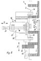
- FIG. 5 shows a modified central, radial working machining unit 10.
- this unit 10 is pivotably and fixably mounted on the column 2 of the carousel machine tool 1. Regardless of whether the processing unit 10 itself can be set in three or in one of the aforementioned coordinates, the unit 10 can also be adjusted in height about a further axis 31 which runs parallel to the Z coordinate.
- the side part 32 of the unit 10 is connected to a hydraulic cylinder unit, likewise provided with an integrated displacement measuring device, which in turn is held on one of the superstructures 3 and 4 of the machine 1 via a fastening part 34.
- This can be advantageous, for example, when it comes to so-called housings for double pumps, which have two fastening flanges on one side, into which fastening holes are to be drilled.
- a multi-spindle drilling head with a plurality of drilling tools 13 is very advantageously suitable for this purpose, as is shown, for example, in the processing unit 10 in FIG. 1.
- the receptacle 6 of the workpiece holding device 5 which can be driven in cycles about the upright central axis of the machine 1, can be equipped with a clamping pallet 36 or 37.
- the respective clamping pallet is a plate-shaped structure and has two, for example diagonally opposite, centering holes 38, to which corresponding centering holes 39 of the receptacle 6 of the workpiece holding device 5 are assigned.
- Corresponding clamping holes 41 of the holding device 5 penetrate corresponding clamping holes 41 of the pallet 36 and 37 and cause the pallet 36, 37 to be clamped on the receiving side 6 of the device 5.
- the clamping pallet 36 can be provided with auxiliary clamping means 42.
- the clamping pallet 37 is provided with a grid arrangement 43 made of threaded holes.
- self-sufficient clamping means (not shown) can be attached to the clamping pallet 37, which in turn then fix the workpiece 7 to the pallet 37.
- the corresponding workpieces are attached to the respective clamping pallet outside of the carousel machine tool 1. Since the respective clamping pallet, which is equipped in this way, can be attached in a simple manner to the receiving side 6 of the device 5, the workpiece to be machined can be attached quickly and very quickly in the Recording 6 of the device 5 can be achieved since practically only the clamping means 40 need to be actuated, since the respective pallet can be quickly attached to the device 5 by means of the centering means 38, 39.
- the centering means 39 can be holes so that common centering pins are used for the holes 38, 39.
- the centering device 39 can also be already arranged on the device 5 pins.
- the clamping pallet is provided with a coding device 44.
- This works together with the aforementioned computer, so that its machining program selects the corresponding machining program based on the respective coding in the coding unit 44 and accordingly controls the respective machining unit 8 and / or 9 and / or 10.
Landscapes
- Engineering & Computer Science (AREA)
- Mechanical Engineering (AREA)
- Automatic Tool Replacement In Machine Tools (AREA)
Applications Claiming Priority (2)
| Application Number | Priority Date | Filing Date | Title |
|---|---|---|---|
| DE19544265 | 1995-11-28 | ||
| DE1995144265 DE19544265C1 (de) | 1995-11-28 | 1995-11-28 | Rundtakt-Werkzeugmaschine |
Publications (1)
| Publication Number | Publication Date |
|---|---|
| EP0776720A1 true EP0776720A1 (fr) | 1997-06-04 |
Family
ID=7778575
Family Applications (1)
| Application Number | Title | Priority Date | Filing Date |
|---|---|---|---|
| EP96118989A Withdrawn EP0776720A1 (fr) | 1995-11-28 | 1996-11-27 | Machine-outil rotative à broches multiples |
Country Status (2)
| Country | Link |
|---|---|
| EP (1) | EP0776720A1 (fr) |
| DE (1) | DE19544265C1 (fr) |
Cited By (1)
| Publication number | Priority date | Publication date | Assignee | Title |
|---|---|---|---|---|
| CN102699774A (zh) * | 2012-06-03 | 2012-10-03 | 浙江金火科技实业有限公司 | 一种双工位自动加工机床及其使用方法 |
Families Citing this family (1)
| Publication number | Priority date | Publication date | Assignee | Title |
|---|---|---|---|---|
| DE19926668C2 (de) * | 1999-06-11 | 2001-04-26 | Giebmanns Karl Heinz | Mehrstationenwerkzeugmaschine |
Citations (7)
| Publication number | Priority date | Publication date | Assignee | Title |
|---|---|---|---|---|
| US2953069A (en) * | 1954-10-18 | 1960-09-20 | Earl R Lowe | Device for multiple machining of work pieces |
| US2972935A (en) * | 1954-05-24 | 1961-02-28 | Bendix Corp | Ball race cutting machine |
| US4014439A (en) * | 1975-01-10 | 1977-03-29 | Wikotool-Systemtechnik Maschinenbau Gmbh & Co. Kg | Eccentric positioning device for tools and workpieces |
| FR2528745A1 (fr) * | 1982-06-21 | 1983-12-23 | Lacombe Laux Ind Services | Procede pour deplacer tridimensionnellement un outil et machine-outil pour sa mise en oeuvre |
| US4473930A (en) * | 1977-12-14 | 1984-10-02 | Witzig & Frank Maschinenbaugesellschaft Mbh | Automatic transfer machine tool with circular supply movement |
| DE3841480C2 (fr) | 1988-12-09 | 1991-02-28 | Elektra-Beckum Lubitz & Co, 4470 Meppen, De | |
| DE3941480A1 (de) * | 1989-12-15 | 1991-06-20 | Witzig & Frank Turmatic Gmbh | Mehrstationen-werkzeugmaschine |
-
1995
- 1995-11-28 DE DE1995144265 patent/DE19544265C1/de not_active Expired - Fee Related
-
1996
- 1996-11-27 EP EP96118989A patent/EP0776720A1/fr not_active Withdrawn
Patent Citations (7)
| Publication number | Priority date | Publication date | Assignee | Title |
|---|---|---|---|---|
| US2972935A (en) * | 1954-05-24 | 1961-02-28 | Bendix Corp | Ball race cutting machine |
| US2953069A (en) * | 1954-10-18 | 1960-09-20 | Earl R Lowe | Device for multiple machining of work pieces |
| US4014439A (en) * | 1975-01-10 | 1977-03-29 | Wikotool-Systemtechnik Maschinenbau Gmbh & Co. Kg | Eccentric positioning device for tools and workpieces |
| US4473930A (en) * | 1977-12-14 | 1984-10-02 | Witzig & Frank Maschinenbaugesellschaft Mbh | Automatic transfer machine tool with circular supply movement |
| FR2528745A1 (fr) * | 1982-06-21 | 1983-12-23 | Lacombe Laux Ind Services | Procede pour deplacer tridimensionnellement un outil et machine-outil pour sa mise en oeuvre |
| DE3841480C2 (fr) | 1988-12-09 | 1991-02-28 | Elektra-Beckum Lubitz & Co, 4470 Meppen, De | |
| DE3941480A1 (de) * | 1989-12-15 | 1991-06-20 | Witzig & Frank Turmatic Gmbh | Mehrstationen-werkzeugmaschine |
Cited By (1)
| Publication number | Priority date | Publication date | Assignee | Title |
|---|---|---|---|---|
| CN102699774A (zh) * | 2012-06-03 | 2012-10-03 | 浙江金火科技实业有限公司 | 一种双工位自动加工机床及其使用方法 |
Also Published As
| Publication number | Publication date |
|---|---|
| DE19544265C1 (de) | 1997-02-20 |
Similar Documents
| Publication | Publication Date | Title |
|---|---|---|
| DE69305768T2 (de) | Werkzeugmaschine | |
| CH629407A5 (de) | Werkzeugmaschine. | |
| EP3535092B1 (fr) | Machine de pierrage avec une pluralité de postes de travail | |
| EP0721819A1 (fr) | Machine-outil | |
| EP2732895A1 (fr) | Machine-outil pour la fabrication de profilés | |
| DE3521350A1 (de) | Vorrichtung zur bearbeitung von pfosten oder sprossen fuer fenster oder tueren | |
| DE10116994A1 (de) | Werkzeugmaschine | |
| DE19919645A1 (de) | Werkzeugmaschine mit Werkzeugspindel und Revolverkopf | |
| DE3241844C1 (de) | Stanzmaschine mit Revolvertrommel | |
| EP1927429A1 (fr) | Machine-outil avec magasin à outils | |
| DE69012938T2 (de) | Werkzeugmaschine mit mehreren Köpfen, vor allem für Holzbearbeitung. | |
| DE1477591A1 (de) | Einstaender-Karussell-Werkzeugmaschine | |
| EP0292712B1 (fr) | Machine à usiner des pièces plates | |
| EP4301180B1 (fr) | Procédé de fabrication de brosses allongées et machine de perçage et de remplissage de brosses pour la mise en oeuvre du procédé | |
| EP0787560B1 (fr) | Dispositif d'usinage des barres, des profilés et similaire | |
| DE2102732A1 (de) | Mehrspindel-Drehautomat | |
| DE4443512A1 (de) | Bearbeitungsmaschine für gerade und gekrümmte Werkstücke, insbesondere aus Holz | |
| DE2604857B2 (de) | Honmaschine | |
| DE10139296B4 (de) | Spannvorrichtung für mehrseitig zu bearbeitende Werkstücke | |
| DE19636139A1 (de) | Werkzeugmaschine für Bohrarbeiten | |
| DE19544265C1 (de) | Rundtakt-Werkzeugmaschine | |
| EP0978340B1 (fr) | Machine de brochage verticale | |
| DE19607883A1 (de) | Vertikal-Drehmaschine | |
| DE1602976B1 (de) | Werkzeugschieber mit Revolverkopf fuer Drehmaschinen | |
| DE69608372T2 (de) | Werkzeugmaschine für Bearbeitungsvorgänge auf langgestreckten Werkstücken wie Profilen und dergleichen |
Legal Events
| Date | Code | Title | Description |
|---|---|---|---|
| PUAI | Public reference made under article 153(3) epc to a published international application that has entered the european phase |
Free format text: ORIGINAL CODE: 0009012 |
|
| AK | Designated contracting states |
Kind code of ref document: A1 Designated state(s): CH DE FR GB IT LI SE |
|
| 17P | Request for examination filed |
Effective date: 19971108 |
|
| 17Q | First examination report despatched |
Effective date: 19991103 |
|
| STAA | Information on the status of an ep patent application or granted ep patent |
Free format text: STATUS: THE APPLICATION IS DEEMED TO BE WITHDRAWN |
|
| 18D | Application deemed to be withdrawn |
Effective date: 20000314 |