EP0776731A1 - Un montage de meulage pour meuler des ciseaux en forme de gouge - Google Patents
Un montage de meulage pour meuler des ciseaux en forme de gouge Download PDFInfo
- Publication number
- EP0776731A1 EP0776731A1 EP96850061A EP96850061A EP0776731A1 EP 0776731 A1 EP0776731 A1 EP 0776731A1 EP 96850061 A EP96850061 A EP 96850061A EP 96850061 A EP96850061 A EP 96850061A EP 0776731 A1 EP0776731 A1 EP 0776731A1
- Authority
- EP
- European Patent Office
- Prior art keywords
- rod
- grinding
- jig
- grindstone
- gouge
- Prior art date
- Legal status (The legal status is an assumption and is not a legal conclusion. Google has not performed a legal analysis and makes no representation as to the accuracy of the status listed.)
- Granted
Links
- 238000000227 grinding Methods 0.000 title claims abstract description 21
- 239000004575 stone Substances 0.000 claims abstract description 3
- 230000003319 supportive effect Effects 0.000 claims abstract 4
- 238000009837 dry grinding Methods 0.000 description 1
- 238000000034 method Methods 0.000 description 1
- XLYOFNOQVPJJNP-UHFFFAOYSA-N water Substances O XLYOFNOQVPJJNP-UHFFFAOYSA-N 0.000 description 1
Images

Classifications
-
- B—PERFORMING OPERATIONS; TRANSPORTING
- B24—GRINDING; POLISHING
- B24B—MACHINES, DEVICES, OR PROCESSES FOR GRINDING OR POLISHING; DRESSING OR CONDITIONING OF ABRADING SURFACES; FEEDING OF GRINDING, POLISHING, OR LAPPING AGENTS
- B24B41/00—Component parts such as frames, beds, carriages, headstocks
- B24B41/06—Work supports, e.g. adjustable steadies
- B24B41/066—Work supports, e.g. adjustable steadies adapted for supporting work in the form of tools, e.g. drills
Definitions
- the present invention relates to a grinding jig for grinding gouge chisels and being of the kind defined in the preamble of Claim 1.
- Finger-shaped turning gouges, firming gouges, scribing gouges, etc., are very difficult to grind.
- the gouges are normally ground straight when received from the supplier, and are therefore often unsuitable for the purpose intended, necessitating the user to re-grind the gouges.
- the gouges are often ground in freehand, using a high-speed grinding wheel (dry grinding) or a grinding stone in water.
- a high-speed grinding wheel dry grinding
- a grinding stone in water.
- uniform grinding of the gouges is achieved with the aid of a hand-held device, in which the gouge is clamped supported solely by one leg against the floor in front of the grindstone. It is quite impossible to finger-grind a gouge precisely and symmetrically with the aid of this tool.
- An object of the present invention is to solve the problem of grinding gouges, and then particularly so-called finger-shaped turning gouges, and also to enable the bevelled surface that defines the cutting edge of the gouge a straight or a convex configuration in addition to the concave configuration afforded by the radius of the grindstone.
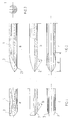
- Figs. 1a-c show the tip of a gouge respectively in side view, in longitudinal sectional view, and from above, and illustrate the gouge tip in the state in which it leaves the supplier, normally ground straight;
- Figs. 2a-c illustrate the tip of a gouge that has been finger-ground in accordance with the invention, respectively from one side of the tip, in part-section and from above;
- Fig. 3 is a view of the gouge profile;
- Fig. 4 illustrates a grinding jig constructed in accordance with the invention; and
- Fig. 5 is a front view of the jig shown in Fig. 4.
- Figs. 1a-c illustrate the tip of a gouge, or turning gouge 1, in the same state as that in which it is normally delivered by the supplier.
- the illustrated gouge has obliquely ground surfaces 2 which define the cutting angle ⁇ of the gouge, and two surfaces 3 ground on the sides of the gouge and forming its so-called side bevels.
- One such finger configuration is shown in Fig. 2.
- the gouge is ground by rotating the gouge during the grinding process so that both obliquely ground surfaces 2 defining the gouge cutting angle, and the side bevels are produced continuously.
- the invention enables a gouge to be ground in this way in a simple manner and with great precision.
- Figs. 4 and 5 illustrate an inventive grinding jig for grinding a gouge 1 to a finger configuration.
- Fig. 4 shows part of a grindstone 4 and a raisable and lowerable universal support 5 located adjacent the grindstone mounting.
- the universal support includes a part 6 which extends parallel with the grindstone axle in a known manner.
- a sleeve 8 which includes a journal bearing 7 is pivotally and displaceably carried by the part 6 of the universal support that extends parallel with the grindstone axle.
- the journal bearing 7 is placed beneath the sleeve 8 at a distance a therefrom, so that the gouge 1 can be twisted and therewith ground at an angle of at least 180°.
- the sleeve 8 has mounted therein a rod 9 which can be moved in the longitudinal direction of the sleeve and which projects out from the sleeve 8 at both ends thereof.
- a so-called locking stirrup 10 is pivotally and lockably mounted at the end of the rod 9 that lies proximal to the grindstone.
- the locking stirrup 10 can thus be swung relative to the longitudinal axis 11 of the rod 9 and locked in different angular positions ⁇ in relation to the longitudinal axis 12 of the gouge 1, said gouge being firmly locked in the locking stirrup 10 by means of a screw 13.
- the screw 13 is provided with a knob 14 and the tip of the screw functions to press the tool lockingly against a V-block 15 of the locking stirrup 10, in a positive manner.
- the end of the rod 9 that lies distal from the grindstone 4 is provided with a stop ring 16 which can be moved axially along said rod end.
- the rod 9 also includes an axially delimited groove 17 into which the end of a screw 18 screwed into the stop ring 16 extends.
- the screw 18 is conveniently integral with a knob 19, and functions to enable the locking ring 16 to be locked in different positions along the rod 9.
- the cutting angle ⁇ is determined by the extent to which the gouge projects from the locking stirrup and by the distance of the part 6 of said universal support 5 from the grindstone.
- a side bevel corresponding to the side bevel shown in Figs. 2a-c is obtained by twisting the locking stirrup and tool 1 around the longitudinal axis of the rod 9.
- the configuration of the side bevel - finger ground - i.e., its length d is determined by the angle ⁇ between the tool and the longitudinal axis 11.
- a suitable angle ⁇ is 20°, wherein the jig may be graduated or likewise marked for larger and smaller angles around this value, as indicated at 19 in Figs. 4 and 5.
- a smaller angle will result in a shorter side bevel, whereas a larger angle will result in a longer side bevel.
- the side bevel will be concave in shape and will have a radius corresponding to the radius of the grindstone.
- the inventive jig can be reset quickly to obtain a straight or a convex side bevel.
- a convex side bevel may be desired, for instance, by lathe operators in respect of certain lathe-cutting work.
- Resetting of the jig is effected by first grinding the gouge with the stop ring 16 locked in a position nearest the sleeve 8. By then moving the stop ring away from the sleeve 8, e.g. through a distance of 10-15 mm, the locking stirrup 10, with the gouge 1, can be moved in a direction towards the grindstone and the heel 21 of the cutting edge (see Fig. 2) will be ground so as to obtain the desired convex side bevel.
- the front edge of the cutting edge can be ground at the same time without changing the jig setting, by allowing the jig to move away from the grindstone, which takes place automatically by virtue of rotation of the grindstone.
- the locking stirrup 10 is locked to the rod 9 by means of a Philip's screw and nut, although it will be understood that other fastener means may be used, for instance a knob-carrying screw.
- the rod 9 be smooth as in the case of the Figs. 4 and 5 embodiment, but may be provided with screw threads which mesh with screw threads in the bearing sleeve 8 for axial movement of the rod 9 in said sleeve, and the stop 16 may be a knob screwed onto the rod 9.
Landscapes
- Engineering & Computer Science (AREA)
- Mechanical Engineering (AREA)
- Finish Polishing, Edge Sharpening, And Grinding By Specific Grinding Devices (AREA)
- Grinding And Polishing Of Tertiary Curved Surfaces And Surfaces With Complex Shapes (AREA)
- Polishing Bodies And Polishing Tools (AREA)
- Constituent Portions Of Griding Lathes, Driving, Sensing And Control (AREA)
Applications Claiming Priority (2)
| Application Number | Priority Date | Filing Date | Title |
|---|---|---|---|
| SE9504246 | 1995-11-28 | ||
| SE9504246A SE510362C2 (sv) | 1995-11-28 | 1995-11-28 | Slipjigg för slipning av skölpjärn |
Publications (2)
| Publication Number | Publication Date |
|---|---|
| EP0776731A1 true EP0776731A1 (fr) | 1997-06-04 |
| EP0776731B1 EP0776731B1 (fr) | 2000-07-12 |
Family
ID=20400385
Family Applications (1)
| Application Number | Title | Priority Date | Filing Date |
|---|---|---|---|
| EP96850061A Expired - Lifetime EP0776731B1 (fr) | 1995-11-28 | 1996-04-17 | Un montage de meulage pour meuler des ciseaux en forme de gouge |
Country Status (6)
| Country | Link |
|---|---|
| EP (1) | EP0776731B1 (fr) |
| JP (1) | JPH09150352A (fr) |
| AT (1) | ATE194537T1 (fr) |
| CA (1) | CA2170208A1 (fr) |
| DE (1) | DE69609295T2 (fr) |
| SE (1) | SE510362C2 (fr) |
Cited By (5)
| Publication number | Priority date | Publication date | Assignee | Title |
|---|---|---|---|---|
| GB2352663A (en) * | 1999-04-06 | 2001-02-07 | Michael Irvine | Jig for use in sharpening cutting tools |
| EP0957331A3 (fr) * | 1998-05-13 | 2001-04-11 | Tormek AB | Capteur d'angles pour des arêtes aigues |
| EP0958888A3 (fr) * | 1998-05-13 | 2001-12-05 | Tormek AB | Montage d'affûtage pour outils tranchants |
| EP1262281A1 (fr) * | 2001-05-30 | 2002-12-04 | Tormek AB | Montage d'affûtage pour outils tranchants |
| CN104802077A (zh) * | 2015-03-01 | 2015-07-29 | 侯如升 | 一种螺旋旋转式摆杆调节机构 |
Families Citing this family (2)
| Publication number | Priority date | Publication date | Assignee | Title |
|---|---|---|---|---|
| SE0201089L (sv) * | 2002-04-11 | 2003-10-12 | Tj Utveckling Ab | Anordning för infästning av skärstål |
| SE2250303A1 (en) * | 2022-03-07 | 2023-03-07 | Tormek Ab | A grinding angle setting device, a grinding system and a method of setting a grinding angle |
Citations (3)
| Publication number | Priority date | Publication date | Assignee | Title |
|---|---|---|---|---|
| US2107921A (en) * | 1936-11-11 | 1938-02-08 | Walter A Weed | Grinding device |
| GB2278305A (en) * | 1992-12-24 | 1994-11-30 | Donnell Michael O | Grinding rest |
| GB2278560A (en) * | 1993-06-01 | 1994-12-07 | Richard Peter Scott | Grinding jig |
-
1995
- 1995-11-28 SE SE9504246A patent/SE510362C2/sv not_active IP Right Cessation
-
1996
- 1996-02-23 CA CA002170208A patent/CA2170208A1/fr not_active Abandoned
- 1996-04-15 JP JP8092742A patent/JPH09150352A/ja active Pending
- 1996-04-17 EP EP96850061A patent/EP0776731B1/fr not_active Expired - Lifetime
- 1996-04-17 AT AT96850061T patent/ATE194537T1/de not_active IP Right Cessation
- 1996-04-17 DE DE69609295T patent/DE69609295T2/de not_active Expired - Lifetime
Patent Citations (3)
| Publication number | Priority date | Publication date | Assignee | Title |
|---|---|---|---|---|
| US2107921A (en) * | 1936-11-11 | 1938-02-08 | Walter A Weed | Grinding device |
| GB2278305A (en) * | 1992-12-24 | 1994-11-30 | Donnell Michael O | Grinding rest |
| GB2278560A (en) * | 1993-06-01 | 1994-12-07 | Richard Peter Scott | Grinding jig |
Cited By (7)
| Publication number | Priority date | Publication date | Assignee | Title |
|---|---|---|---|---|
| EP0957331A3 (fr) * | 1998-05-13 | 2001-04-11 | Tormek AB | Capteur d'angles pour des arêtes aigues |
| EP0958888A3 (fr) * | 1998-05-13 | 2001-12-05 | Tormek AB | Montage d'affûtage pour outils tranchants |
| GB2352663A (en) * | 1999-04-06 | 2001-02-07 | Michael Irvine | Jig for use in sharpening cutting tools |
| GB2352663B (en) * | 1999-04-06 | 2003-10-22 | Michael Irvine | Jig for use in sharpening cutting implement for use in wood turning |
| EP1262281A1 (fr) * | 2001-05-30 | 2002-12-04 | Tormek AB | Montage d'affûtage pour outils tranchants |
| CN104802077A (zh) * | 2015-03-01 | 2015-07-29 | 侯如升 | 一种螺旋旋转式摆杆调节机构 |
| CN104802077B (zh) * | 2015-03-01 | 2017-06-20 | 东莞市显科模具五金有限公司 | 一种螺旋旋转式摆杆调节机构 |
Also Published As
| Publication number | Publication date |
|---|---|
| EP0776731B1 (fr) | 2000-07-12 |
| ATE194537T1 (de) | 2000-07-15 |
| SE9504246L (sv) | 1997-05-29 |
| DE69609295D1 (de) | 2000-08-17 |
| JPH09150352A (ja) | 1997-06-10 |
| SE510362C2 (sv) | 1999-05-17 |
| DE69609295T2 (de) | 2000-12-21 |
| CA2170208A1 (fr) | 1997-05-29 |
| SE9504246D0 (sv) | 1995-11-28 |
Similar Documents
| Publication | Publication Date | Title |
|---|---|---|
| US6393712B1 (en) | Grinding jig for grinding gouge chisels | |
| DE69729396T2 (de) | Schleifscheibenanordnung zum Einsatz bei einer Präzisions-Spiralbohrerschleifvorrichtung | |
| US5810649A (en) | Tool guide for sharpening woodcarving and tools | |
| DE2538737C2 (de) | Werkzeug-Schleifmaschine für Profilwerkzeuge | |
| EP0286266A1 (fr) | Appareil pour affûter des outils de coupe | |
| EP3173187A1 (fr) | Tronçonneuse portative manuelle | |
| EP0776731B1 (fr) | Un montage de meulage pour meuler des ciseaux en forme de gouge | |
| US4974372A (en) | Universal device for sharpening drill bits | |
| US4270269A (en) | Combination pipe-cutter and deburring tool | |
| EP0958888B1 (fr) | Montage d'affûtage pour outils tranchants | |
| EP1479495A2 (fr) | Procédé et machine-outil pour affleurer et racler des chants d'une pièce en forme de plaque | |
| US4912881A (en) | Multiple angle dressing device for tools and stock | |
| US5454166A (en) | Deburring tool | |
| AT523721B1 (de) | Vorrichtung zum Schleifen von Klingen | |
| EP0842012B1 (fr) | Ponceuse vibrante | |
| DE102024108934A1 (de) | Schleifhilfe für einen Rollschleifer und Rollschleifer-Set | |
| US2512888A (en) | Apparatus for grinding drills | |
| US3535826A (en) | Template-controlled tool grinding machines | |
| US2720731A (en) | Work holder for tap sharpening | |
| US3084485A (en) | Drill grinder | |
| EP1530988B1 (fr) | Appareil pour meuler et affuter manuellement les carres de la semelle | |
| US4198950A (en) | Dressing device for wheels or the like | |
| DE713786C (de) | Einrichtung zum Schleifen des Spanwinkels an Schneideisen | |
| DE19913789C2 (de) | Verfahren und Reparaturstift zur Wiederherstellung einer Schneidfläche an einem Schneidwerkzeug | |
| DE1955787U (de) | Schleifvorrichtung fuer elektroden. |
Legal Events
| Date | Code | Title | Description |
|---|---|---|---|
| PUAI | Public reference made under article 153(3) epc to a published international application that has entered the european phase |
Free format text: ORIGINAL CODE: 0009012 |
|
| AK | Designated contracting states |
Kind code of ref document: A1 Designated state(s): AT BE CH DE FR GB LI NL SE |
|
| 17P | Request for examination filed |
Effective date: 19971204 |
|
| GRAG | Despatch of communication of intention to grant |
Free format text: ORIGINAL CODE: EPIDOS AGRA |
|
| GRAG | Despatch of communication of intention to grant |
Free format text: ORIGINAL CODE: EPIDOS AGRA |
|
| GRAH | Despatch of communication of intention to grant a patent |
Free format text: ORIGINAL CODE: EPIDOS IGRA |
|
| 17Q | First examination report despatched |
Effective date: 19990826 |
|
| GRAH | Despatch of communication of intention to grant a patent |
Free format text: ORIGINAL CODE: EPIDOS IGRA |
|
| GRAA | (expected) grant |
Free format text: ORIGINAL CODE: 0009210 |
|
| AK | Designated contracting states |
Kind code of ref document: B1 Designated state(s): AT BE CH DE FR GB LI NL SE |
|
| PG25 | Lapsed in a contracting state [announced via postgrant information from national office to epo] |
Ref country code: NL Free format text: LAPSE BECAUSE OF FAILURE TO SUBMIT A TRANSLATION OF THE DESCRIPTION OR TO PAY THE FEE WITHIN THE PRESCRIBED TIME-LIMIT Effective date: 20000712 Ref country code: LI Free format text: LAPSE BECAUSE OF FAILURE TO SUBMIT A TRANSLATION OF THE DESCRIPTION OR TO PAY THE FEE WITHIN THE PRESCRIBED TIME-LIMIT Effective date: 20000712 Ref country code: CH Free format text: LAPSE BECAUSE OF FAILURE TO SUBMIT A TRANSLATION OF THE DESCRIPTION OR TO PAY THE FEE WITHIN THE PRESCRIBED TIME-LIMIT Effective date: 20000712 Ref country code: BE Free format text: LAPSE BECAUSE OF FAILURE TO SUBMIT A TRANSLATION OF THE DESCRIPTION OR TO PAY THE FEE WITHIN THE PRESCRIBED TIME-LIMIT Effective date: 20000712 Ref country code: AT Free format text: LAPSE BECAUSE OF FAILURE TO SUBMIT A TRANSLATION OF THE DESCRIPTION OR TO PAY THE FEE WITHIN THE PRESCRIBED TIME-LIMIT Effective date: 20000712 |
|
| REF | Corresponds to: |
Ref document number: 194537 Country of ref document: AT Date of ref document: 20000715 Kind code of ref document: T |
|
| REG | Reference to a national code |
Ref country code: CH Ref legal event code: EP |
|
| REF | Corresponds to: |
Ref document number: 69609295 Country of ref document: DE Date of ref document: 20000817 |
|
| ET | Fr: translation filed | ||
| PG25 | Lapsed in a contracting state [announced via postgrant information from national office to epo] |
Ref country code: SE Free format text: LAPSE BECAUSE OF FAILURE TO SUBMIT A TRANSLATION OF THE DESCRIPTION OR TO PAY THE FEE WITHIN THE PRESCRIBED TIME-LIMIT Effective date: 20001012 |
|
| NLV1 | Nl: lapsed or annulled due to failure to fulfill the requirements of art. 29p and 29m of the patents act | ||
| REG | Reference to a national code |
Ref country code: CH Ref legal event code: PL |
|
| PLBE | No opposition filed within time limit |
Free format text: ORIGINAL CODE: 0009261 |
|
| STAA | Information on the status of an ep patent application or granted ep patent |
Free format text: STATUS: NO OPPOSITION FILED WITHIN TIME LIMIT |
|
| 26N | No opposition filed | ||
| REG | Reference to a national code |
Ref country code: GB Ref legal event code: IF02 |
|
| REG | Reference to a national code |
Ref country code: FR Ref legal event code: PLFP Year of fee payment: 20 |
|
| PGFP | Annual fee paid to national office [announced via postgrant information from national office to epo] |
Ref country code: GB Payment date: 20150415 Year of fee payment: 20 Ref country code: DE Payment date: 20150414 Year of fee payment: 20 |
|
| PGFP | Annual fee paid to national office [announced via postgrant information from national office to epo] |
Ref country code: FR Payment date: 20150408 Year of fee payment: 20 |
|
| REG | Reference to a national code |
Ref country code: DE Ref legal event code: R071 Ref document number: 69609295 Country of ref document: DE |
|
| REG | Reference to a national code |
Ref country code: GB Ref legal event code: PE20 Expiry date: 20160416 |
|
| PG25 | Lapsed in a contracting state [announced via postgrant information from national office to epo] |
Ref country code: GB Free format text: LAPSE BECAUSE OF EXPIRATION OF PROTECTION Effective date: 20160416 |