EP0776789B1 - Structure de connexion d'un faisceau de cables du tableau de bord d'un véhicule - Google Patents
Structure de connexion d'un faisceau de cables du tableau de bord d'un véhicule Download PDFInfo
- Publication number
- EP0776789B1 EP0776789B1 EP96119009A EP96119009A EP0776789B1 EP 0776789 B1 EP0776789 B1 EP 0776789B1 EP 96119009 A EP96119009 A EP 96119009A EP 96119009 A EP96119009 A EP 96119009A EP 0776789 B1 EP0776789 B1 EP 0776789B1
- Authority
- EP
- European Patent Office
- Prior art keywords
- electric connection
- instrument panel
- connection box
- harness
- connector
- Prior art date
- Legal status (The legal status is an assumption and is not a legal conclusion. Google has not performed a legal analysis and makes no representation as to the accuracy of the status listed.)
- Expired - Lifetime
Links
Images



Classifications
-
- B—PERFORMING OPERATIONS; TRANSPORTING
- B60—VEHICLES IN GENERAL
- B60R—VEHICLES, VEHICLE FITTINGS, OR VEHICLE PARTS, NOT OTHERWISE PROVIDED FOR
- B60R16/00—Electric or fluid circuits specially adapted for vehicles and not otherwise provided for; Arrangement of elements of electric or fluid circuits specially adapted for vehicles and not otherwise provided for
- B60R16/02—Electric or fluid circuits specially adapted for vehicles and not otherwise provided for; Arrangement of elements of electric or fluid circuits specially adapted for vehicles and not otherwise provided for electric constitutive elements
- B60R16/0207—Wire harnesses
-
- B—PERFORMING OPERATIONS; TRANSPORTING
- B60—VEHICLES IN GENERAL
- B60K—ARRANGEMENT OR MOUNTING OF PROPULSION UNITS OR OF TRANSMISSIONS IN VEHICLES; ARRANGEMENT OR MOUNTING OF PLURAL DIVERSE PRIME-MOVERS IN VEHICLES; AUXILIARY DRIVES FOR VEHICLES; INSTRUMENTATION OR DASHBOARDS FOR VEHICLES; ARRANGEMENTS IN CONNECTION WITH COOLING, AIR INTAKE, GAS EXHAUST OR FUEL SUPPLY OF PROPULSION UNITS IN VEHICLES
- B60K37/00—Dashboards
- B60K37/10—Arrangements for attaching the dashboard to the vehicle
-
- B—PERFORMING OPERATIONS; TRANSPORTING
- B60—VEHICLES IN GENERAL
- B60K—ARRANGEMENT OR MOUNTING OF PROPULSION UNITS OR OF TRANSMISSIONS IN VEHICLES; ARRANGEMENT OR MOUNTING OF PLURAL DIVERSE PRIME-MOVERS IN VEHICLES; AUXILIARY DRIVES FOR VEHICLES; INSTRUMENTATION OR DASHBOARDS FOR VEHICLES; ARRANGEMENTS IN CONNECTION WITH COOLING, AIR INTAKE, GAS EXHAUST OR FUEL SUPPLY OF PROPULSION UNITS IN VEHICLES
- B60K37/00—Dashboards
- B60K37/20—Dashboard panels
-
- B—PERFORMING OPERATIONS; TRANSPORTING
- B60—VEHICLES IN GENERAL
- B60K—ARRANGEMENT OR MOUNTING OF PROPULSION UNITS OR OF TRANSMISSIONS IN VEHICLES; ARRANGEMENT OR MOUNTING OF PLURAL DIVERSE PRIME-MOVERS IN VEHICLES; AUXILIARY DRIVES FOR VEHICLES; INSTRUMENTATION OR DASHBOARDS FOR VEHICLES; ARRANGEMENTS IN CONNECTION WITH COOLING, AIR INTAKE, GAS EXHAUST OR FUEL SUPPLY OF PROPULSION UNITS IN VEHICLES
- B60K2360/00—Indexing scheme associated with groups B60K35/00 or B60K37/00 relating to details of instruments or dashboards
- B60K2360/40—Hardware adaptations for dashboards or instruments
- B60K2360/46—Electrical connections
Definitions
- This invention relates to an instrument panel harness-connecting construction having an electric connection box construction. More specifically the invention relates to a construction in which a pair of electric connection boxes are attached respectively to a body panel and an instrument panel, and are fitted together at their connector portions. The efficiency of mounting instrument panel harnesses is improved by the use of these electric connection boxes.
- an instrument panel harness and a cowl harness are arranged between an instrument panel and a cowl panel of a body in an automobile.
- Both the instrument panel harness and the cowl harness include a power wire, a signal wire and an earth or ground wire in a mixed manner.
- An electric connection box 1, comprising a junction box (shown in Figs. 1 and 2) to be connected to these wire harnesses, is assembled in such a manner that the electric connection box 1 is connected to either the instrument panel harness W/H1 or the cowl harness W/H2 through a connector.
- the cowl harness W/H2 is arranged along a cowl panel 2 of the body, and is fixed by clamps while the instrument panel harness W/H1 is arranged along an instrument panel 3, and is fixed by clamps.
- the instrument panel 3 is attached to the cowl panel 2.
- connectors 4 of a front harness W/H3, a floor harness W/H4, a roof harness W/H5 and a door harness W/H6 are fitted respectively in connector fitting portions 1a of the electric connection box 1.
- a connector of either the instrument panel harness or the cowl harness (whichever one is not connected to the electric connection box 1 above) is fitted in the connector fitting portion 1a of the electric connection box 1.
- the electric connection box 1 is fixed to the body panel at the cowl side.
- the operator's hands when connecting many connectors to the electric connection box, the operator's hands must be extended into a blind space between the cowl panel 2 on the body and the instrument panel 3 from the lower side so as to effect this connecting operation. Also, the operator must crouch and stoop during the connecting operation, which imposes a large physical burden on the operator. Further, since the floor harness, the front harness, the roof harness, the door harness and either the instrument panel harness or the cowl harness must be connected to the electric connection box, many connectors must be fitted in the electric connection box, much time is required for the connector-connecting operation.
- EP-0334343 A2 discloses a wire harness coupling unit intended for use on a vehicular instrument panel to facilitate coupling of connectors of a wire harness on the instrument panel with corresponding connectors of a wire harness on the dashboard side.
- the wire harness coupling unit essentially includes: a male coupler member provided on one of the dashboard and instrument panel and carrying connectors of one of the wire harnesses in predetermined positions; a female coupler member provided on the other one of the dashboard and instrument panel in face-to-face relation with the male coupler member and carrying connectors of the other one of the first and second wire harnesses in predetermined positions; the male and female coupler members being engageable with each other upon assembling the instrument panel onto the dashboard to couple the connectors of the two wire harnesses with each other.
- the present invention has been made in view of the above problems, and an object of the invention is to provide an electric connection box construction in which the connection of wire harnesses, arranged between an instrument panel and a body, can be effected easily, and by the use of this electric connection box, instrument panel harnesses can be easily connected to other wire harnesses at one time, thereby reducing the time and labor required for the operation.
- an electric connection box construction for an automobile in which a pair of electric connection boxes are mounted respectively on large-size panels in the automobile, and have respective connector portions fitted together; one or each of the electric connection boxes being movably supported within an outer frame, which is fixedly mounted on the associated panel, through resilient support members.
- each of the resilient support members comprises a rubber member or a spring with one end of the resilient support member fixed to the outer frame while the other end thereof is fixed to an outer surface of the electric connection box.
- the resilient support members are spaced from one another, and the electric connection box is movable within the outer frame so as to absorb a dimensional error.
- the electric connection box is movably mounted on the large-size panel as described above, and with this construction the connector portion of the electric connection box can be easily fitted in the mating connector portion while absorbing a dimensional error.
- the two connector portions cannot be easily fitted together if the two electric connection boxes are fixed.
- this fitting operation can be effected smoothly.
- an instrument panel harness-connecting construction wherein a pair of electric connection boxes are mounted respectively on an instrument panel and a body panel.
- the electric connection box mounted on the instrument panel has a collective-connecting connector portion for connection to instrument panel harnesses and for connection to wire harnesses mounted on a body.
- the electric connection box mounted on the body panel has a first collective-connecting connector portion for fitting connection to the collective-connecting connector portion, and a plurality of second connector portions for fitting to connectors connected to a front harness, a floor harness, a roof harness and a door harness.
- the two connector portions of the two electric connection boxes which are to be fitted together simultaneously when attaching the instrument panel of a large size to the body panel, are fixed to the panels, the two connector portions can not be easily fitted together if they are even slightly out of registry with each other.
- the connector fitting operation can be carried out easily even when a dimensional error is produced by a slightly deviated direction of mounting of the instrument panel.
- the electric connection box mounted on the instrument panel is movable relative to an outer frame while the other electric connection box is fixedly mounted on the body panel.
- the function of the conventional junction box (fixed to the body panel after the instrument panel is attached to the body panel) is divided into that of the electric connection box, beforehand attached to the instrument panel, and that of the electric connection box beforehand attached to the body panel. Simultaneously when fixing the instrument panel to the body panel, the two electric connection boxes are fitted together, thereby connecting the instrument panel harnesses to the other wire harnesses at one time.
- the connector fitting operation can be effected for all the connectors at one time, in contrast with the conventional construction, and therefore the time and labor required for the operation are greatly reduced. Specifically, it is no longer necessary, after the instrument panel is attached to the body panel, to fit the connectors of the wire harnesses into the electric connection box or to fix the electric connection box to the body after this connector fitting operation.
- the electric connection box mounted on the body panel comprises a connector block having an internal circuit connecting the second connector portions to the first connector portion.
- the collective-connecting connector portion is fixed by a fastening member, and the fastening member also serves to fix the instrument panel and the body panel together.
- the two electric connection boxes at least one of which is movable, are thus fastened and fixed together by the fastening member such as a bolt, the shaking of the electric connection boxes due to vibrations developing during the travel of the automobile is prevented. Further, since the fastening member is also used to fix the instrument panel to the body panel, the time and labor required for the operation are reduced.
- the fastening member such as a bolt
- the instrument panel harnesses include a cowl harness that does not include a power circuit, and the power circuit is connected to the electric connection box mounted on the body panel.
- an electric connection box in which an insulating plate, having a bus bar fixed thereto, is mounted within a casing, comprising an upper case and a lower case, through resilient support members so that the insulating plate is movable relative to the casing.
- Connectors are fittingly connected to tabs formed on the bus bar, and the connectors are inserted into the casing through respective connector fitting holes formed through the upper case and/or the lower case.
- the connectors project outwardly from the casing in such a manner that a gap is formed between an outer peripheral surface of each of the connectors and a peripheral edge of the associated connector fitting hole so that when each of the connectors is to be fitted in a mating connector, it is movable to a fitting position.
- the connectors mounted on the electric connection box are movable relative to the casing, and therefore when each connector is to be fitted in the mating connector, it can be easily fitted in the mating connector while absorbing a dimensional error.
- the connectors are of the multi-pole type, the two connector portions can not be easily fitted together if the two are fixed.
- the fitting operation can be carried out smoothly.
- an automobile instrument panel wire harness-mounting construction in which an electric connection box attached to an instrument panel is connected to a wire harness mounted on the instrument panel, and the electric connection box has a collective-connecting connector portion for connection to wire harnesses mounted on a body; a second electric connection box attached to a body panel having a first collective-connecting connector portion fitted on the collective-connecting connector portion, and a plurality of second connector portions fitted onto connectors connected to a front harness, a floor harness, a roof harness and a door harness; and one or both of the electric connection boxes, attached respectively to the instrument panel and the body panel, comprise a movable-type electric connection box.
- the electric connection box attached to the instrument panel comprises the movable-type electric connection box while the second electric connection box is fixedly mounted on the body panel.
- the resilient support members each in the form of a rubber member or a spring, extend between the casing, which comprises the upper and lower cases and is fixed to the instrument panel, and the insulating plate, mounted within the casing, so that the insulating plate, the bus bar fixed to the insulating plate, and the collective-connecting connector portion connected to the bus bar are movable within the movable-type electric connection box.
- the two connector portions of the two electric connection boxes which are to be fitted together simultaneously when attaching the instrument panel to the body panel, are fixed to the panels, the two connector portions can not be easily fitted together if they are even slightly out of registry with each other.
- the connector fitting operation can be carried out easily even when a dimensional error is produced by a slightly deviated direction of mounting of the instrument panel.
- the function of the conventional junction box (fixed to the body panel after the instrument panel is attached to the body panel) is divided into that of the electric connection box, beforehand attached to the instrument panel, and that of the electric connection box beforehand attached to the body panel. Simultaneously when fixing the instrument panel to the body panel, the two electric connection boxes are fitted together, thereby connecting the instrument panel harnesses to the other wire harnesses at one time.
- the connector fitting operation can be effected for all the connectors at one time, in contrast with the conventional construction, and therefore the time and labor required for the operation are greatly reduced. Specifically, it is no longer necessary, after the instrument panel is attached to the body panel, to fit the connectors of the wire harnesses into the electric connection box or to fix the electric connection box to the body after this connector fitting operation.
- the wire harness mounted on the instrument panel includes the instrument panel harness, and a cowl harness that does not include a power circuit, and the power circuit is connected to the electric connection box mounted on the body panel.
- Two kinds of wire harnesses that is, an instrument panel harness and a cowl harness which have be separate from each other in the conventional construction, are combined together into the wire harnesses mounted on the instrument panel except for the wire connected to the power circuit. With this arrangement it is necessary to arrange only one large-size wire harness in a narrow space between the instrument panel and the body panel, which improves the efficiency of the operation.
- the function of the conventional junction box is divided into that of an electric connection box 12 (which is to be connected to wire harnesses 11 mounted along an instrument panel 10) and that of an electric connection box comprising a connector block 15 to be connected to wire harnesses mounted along a body panel (cowl panel) 14.
- the instrument panel 10 is attached to the body panel 14 in an automobile assembly line.
- the wire harnesses mounted on the instrument panel 10 are electrically connected respectively to the wire harnesses mounted on the body panel 14 by fitting the electric connection box 12 and the connector block 15 together simultaneously when attaching the instrument panel 10 to the body panel 14.
- the wire harnesses 11, mounted on the instrument panel 10, include a conventional instrument panel harness, and a conventional cowl harness less a power circuit 18 connected to a power source 17.
- the wire harnesses 11 are arranged and held in position by clamps (not shown) on the instrument panel 10.
- two kinds of wire harnesses that is, an instrument panel harness and a cowl harness to be arranged between the instrument panel 10 and the body panel 14
- the wire harnesses 11 are connected to the electric connection box 12, and with this construction the number of circuits which are to be electrically connected when the electric connection box 12 is fitted in the connector block 15 at their connector portions is reduced.
- the wire harnesses mounted on the body panel 14 separating an engine room side A and a compartment side B from each other, include the power circuit 18 connecting the power source 17 to the connector block 15.
- a front harness 20, a floor harness 21, a roof harness 22 and a door harness 23 are connected to the connector block 15 through respective connectors.
- the electric connection box 12 is mounted on an outer frame 26 (fixed to the instrument panel 10) through resilient support members 27, so that the electric connection box 12 is movable relative to the instrument panel 10 so as to absorb a dimensional error.
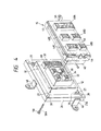
- the electric connection box 12 comprises an upper case 30 and a lower case 31, and a bus bar 32 (shown in phantom in Fig. 4), constituting an internal circuit, is mounted or housed within a space formed by the upper and lower cases 30 and 31. Relays and fuses 60, connected to this bus bar, are mounted on the electric connection box 12.
- a collective-connecting connector portion 33 for connection to the connector block 15 is formed on an upper surface of the upper case 30.
- Male terminals 34, connected to the bus bar 32, are projected within the collective-connecting connector portion 33.
- Mounting portions 35 are provided respectively at four corners of an outer peripheral surface of the upper casing 30, and the resilient support members 27 are mounted respectively at the mounting portions 35.
- the mounting portion 35 is in the form of a hole formed in the upper case 30, and the resilient support member 27 is secured to the mounting portion 35 by a pin or the like extending through the resilient support member.
- Connector fitting portions 37 are formed on a bottom surface of the lower case 31, and connectors 36 connected to ends of the wire harnesses 11 to be connected to the electric connection box 12 are fitted in the connector fitting portions 37.
- a through hole 38 extends through the upper and lower cases 30 and 31 at a central portion of the collective-connecting connector portion 33, and a bolt (fastening member) 58 is passed through this through hole 38 so as to fasten the electric connection box 12 to the connector block 15.
- the outer frame 26 of a square shape surrounds the case of the electric connection box 12, and is spaced a predetermined distance from the outer peripheral surface of this case.
- Mounting portions 39 are formed respectively at the inner sides of the four corners of the outer frame 26 respectively facing the mounting portions 35, and the resilient support members 27 are mounted respectively at the mounting portions 39.
- the mounting portions 39 are in the form of a groove extending downwardly from an upper surface of the outer frame 26, and a bulged portion 27a of the resilient support member 27 is engaged in this groove, thereby supporting the resilient support member 27.
- Brackets 40 are formed respectively on predetermined portions of the outer peripheral surface of the outer frame 26, and the outer frame 26 is attached to the instrument panel 10 through the brackets 40.
- the resilient support member 27 comprises a rubber member or a spring, and the resilient support members 27 support the electric connection box 12 within the outer frame 26 in such a manner that the electric connection box 12 is movable so as to absorb a dimensional error.
- a mounting portion (not shown), having a through hole through which the above-mentioned pin extends, is formed at one end of the resilient support member 27 which is inserted and retained in the mounting portion 35.
- the bulged portion 27a which is engaged in the groove (mounting portion), is formed at the other end of the resilient support member 27 which is inserted and retained in the mounting portion 39 of the outer frame 26.
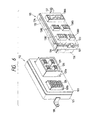
- the connector block 15 to be fixed to the body panel 14 comprises an upper case 42 and a lower case 43, and a bus bar 44 (shown in phantom in Fig. 4), constituting an internal circuit, is housed or mounted within a space formed by the cases 42 and 43.
- a first collective-connecting connector portion 45 for fitting connection to the collective-connecting connector portion 33 is formed on an upper surface of the upper case 42.
- Female terminals 47, connected to the bus bar 44, are projected within the first collective-connecting connector portion 45, and are respectively fitted on and electrically connected to the male terminals 34 in the collective-connecting connector portion 33 when the first collective-connecting connector portion 45 and the collective-connecting connector portion 33 are fitted together.
- Brackets 46 are formed respectively on predetermined portions of the outer peripheral surface of the upper case 42, and the connector block 15 is attached to the body panel 14 through the brackets 46.
- a plurality of second connector portions for fitting respectively on the plurality of wire harnesses are formed on the bottom surface of the lower case 43.
- five second connector portions 48A to 48E are provided.
- a connector 50 of the power circuit 18 is fitted in the second connector portion 48A, and connectors 51, 52, 53 and 54, secured respectively to ends of the front harness 20, the floor harness 21, the roof harness 22 and the door harness 23, are fitted respectively in the second connector portions 48B to 48E.
- the first collective-connecting connector portion 45 is connected to the second connector portions 48A to 48E by the bus bar 44 constituting the internal circuit.
- a through hole 56 is formed through the upper and lower cases 42 and 43 at a central portion of the first collective-connecting connector portion 45, and this through hole 56 is aligned with the through hole 38.
- a through hole 10a is formed through the instrument panel 10, and a threaded hole 14a is formed through the body panel 14.
- a threaded shank 58a of the bolt 58 is passed through the aligned through holes 10a, 38 and 56 from the outer side of the instrument panel 10, and is threaded into the threaded hole 14a, thereby positively fitting the first collective-connecting connector portion 45 and the collective-connecting connector portion 33 together, and also securing the instrument panel 10 to the body panel 14.
- the wire harnesses 11 are arranged in position on the instrument panel 10, with the connectors 36 of the wire harnesses 11 fitted in the respective connector fitting portions 37 of the electric connection box 12.
- the brackets 40 formed on the outer frame 26 of the electric connection box 12, are secured by bolts to the inner side of the instrument panel 10, thereby fixing the electric connection box 12.
- the connector block 15 is fixedly secured to the body panel 14, and the connector 50 of the power circuit 18 and the connectors 51 to 54 of the wire harnesses 20 to 23 are fitted in and connected to the second connector portions 48A to 48E of the connector block 15, respectively.
- the power circuit 18 and the wire harnesses 20 to 23 are arranged in position on the body panel 14.
- the fitting of the connectors 36 and 50 to 54, the attachment of the electric connection box 12 to the instrument panel 10, and the attachment of the connector block 15 to the body panel 14 can be effected in a wide space available before the instrument panel 10 is attached to the body panel 14, and therefore these operations can be carried out efficiently.
- the instrument panel 10 is attached to the body panel 14.
- the collective-connecting connector portion 33 of the electric connection box 12 is first brought into contact with the first collective-connecting connector portion 45 of the connector block 15.
- the resilient support members 27 allow the electric connection box 12 to move, thereby eliminating this misregistration.
- the electric connection box 12 is movable, and therefore the fitting position is finely adjusted, so that the collective-connecting connector portion 33 and the first collective-connecting connector portion 45 can be easily fitted together.
- the threaded shank 58a of the bolt 58 is passed through the through holes 10a, 38 and 56 from the outer side of the instrument panel 10, and is threaded into the threaded hole 14a formed through the body panel 14.
- the collective-connecting connector portion 33 is fitted in and electrically connected to the first collective-connecting connector portion 45, and also the instrument panel 10 is fixedly secured to the body panel 14, thus completing all the mounting operations.
- the collective-connecting connector portion 33 and the first collective-connecting connector portion 45 are fitted and connected together by tightening the bolt 58, and therefore the two can be electrically connected together positively and easily.
- the bolt 58 for the fitting connection of the electric connection box 12 to the connector block 15 also serves as a fastening member for fixing the instrument panel 10 to the body panel 14, and therefore the time and labor required for the operation are reduced.
- the instrument panel 10 When disassembling the automobile, the instrument panel 10 can be easily removed from the body panel 14 by loosening the bolt 58, and the wire harnesses 11 can be removed from the instrument panel 10 in a separate, wide space. Therefore, the removal of the wire harnesses 11 can be effected efficiently.
- the present invention is not to be limited to the above embodiment.
- a fastening rod (comprising a shaft member) having a retaining projection formed at its distal end, in which case the fastening rod is passed through the instrument panel, the electric connection box, the connector block and the body panel, and then is rotated so as to retain the retaining projection on the body panel.
- the electric connection box is movably mounted on the instrument panel through the resilient support members
- the electric connection box, mounted on the instrument panel may be fixed while the connector block, mounted on the body panel, may be movable.
- both the electric connection box on the instrument panel and the connector block on the body panel may be movable. Even if the electric connection box and the connector block are both movable, they will not be moved by vibrations developing during the travel of the automobile since the electric connection box and the connector block are fixed to the instrument panel and the body panel by the fastening member.
- a movable-type electric connection box 112 for connection to a wire harness 111 mounted on an instrument panel 110, as well as a fixed electric connection box 115 for connection to wire harnesses mounted on a body panel 114, is provided, and the function of the conventional electric connection box (that is, a junction box) is divided into that of the movable-type electric connection box 112 and that of the electric connection box 115.
- the wire harness 111, mounted on the instrument panel 110 is electrically connected to the wire harnesses mounted on the body panel 114 by fittingly connecting the two electric connection boxes 112 and 115 together simultaneously when attaching the instrument panel 110 to the body panel 114.
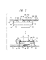
- an insulating plate 123 having bus bars 122 fixed thereto, is mounted within a casing, comprising an upper case 120 and a lower case 121, through resilient support members 124 so that the insulating plate 123 is movable relative to the casing.
- a collective-connecting connector 125 for connection to the electric connection box 115 on the body panel 114 is mounted on the insulating plate 123, and tabs 122a, formed on the bus bars 122, are fitted in the connector 125.
- the connector 125 is projected outwardly from the upper case 120 of the casing, and is movable together with the insulating plate 123 so as to adjust a connector fitting position.
- a fuse block 126 having relays and fuses mounted thereon, and a harness connector 127 for connection to the wire harness 111 are fitted on tabs formed on the bus bars 122, and therefore like the connector 125, the fuse block 126 and the harness connector 127 are also movable relative to the casing.
- the upper case 120 has a connector fitting hole 120a through which the collective-connecting connector 125 projects outwardly from the casing, and the upper case 120 also has a fuse fitting hole 120b through which the fuse block 126 projects outwardly from the casing.
- the peripheral edge of the fitting hole 120a surrounds an outer peripheral surface of the collective-connecting connector 125 in such a manner that a predetermined gap is formed therebetween, and also the peripheral edge of the fitting hole 120b surrounds an outer peripheral surface of the fuse block 126 in such a manner that a predetermined gap is formed therebetween.
- the connector 125 and the fuse block 126 are inserted into the casing, and are movable relative to the casing.
- Mounting portions 120c each in the form of a groove are formed respectively in four corners of the upper case 120, and a mounting portion 124a, formed at one end of each resilient support member 124, is inserted in and fixed to the corresponding mounting portion 120c.
- the lower case 121 has a connector fitting hole 121a through which the harness connector 127 projects outwardly from the casing.
- the peripheral edge of the connector fitting hole 121a surrounds an outer peripheral surface of the harness connector 127 in such a manner that a predetermined gap is formed therebetween, and the harness connector 127 is inserted into the casing, and is movable relative to the casing.
- Brackets 128 are formed respectively at predetermined portions of the outer peripheral surface of the lower case 121, and the casing is attached to the instrument panel 110 through these brackets 128.
- the bus bars 122 are fixedly secured to the opposite sides or faces of the insulating plate 123 in predetermined patterns.
- the insulating plate 123 is of a laminated construction, with bus bars interposed between layers of the laminated insulating plate 123, each of tabs, formed on the bus bars, extends through the corresponding layer of the insulating plate 123, and is fitted in an associated one of the above connectors and a fuse.
- Mounting portions 123a are provided respectively at four corners of the insulating plate 123, and the resilient support members 124 are fixedly secured respectively to the mounting portions 123a.
- the mounting portion 123a is in the form of a groove formed in the peripheral edge of the insulating plate 123, and one end of the resilient support member 124 is inserted into the mounting portion 123a, and is fixed thereto by a pin or the like extending through the resilient support member 124.
- the resilient support member 124 comprises a rubber member or a spring, and the resilient support members 124 extend and are connected between the upper case 120 and the insulating plate 123, so that the insulating plate 123 is movable within the casing together with the bus bars 122 and the collective-connecting connector 125, the fuse block 126 and the harness connector 127 which are connected to the bus bars 122.
- Male terminals 129 connected respectively to the corresponding tabs 122a of the bus bars 122, are projected within the collective-connecting connector 125.
- the collective-connecting connector 125 is mounted or held on the insulating plate 123, and in an assembled condition of the movable-type electric connection box 112, the connector 125 is movable within the connector fitting hole 120a through the resilient support members 124 and the insulating plate 123.
- terminals (not shown), connected respectively to the corresponding tabs 122a of the bus bars 122, are provided within the fuse block 126, and by fitting these terminals respectively on these tabs 122a, the fuse block 126 is mounted or held on the insulating plate 123.
- the harness connector 127 has terminals (not shown) connected respectively to the corresponding tabs 122a of the bus bars 122, and by fitting these terminals on these tabs 122a, the harness connector 127 is mounted or held on the insulating plate 123.
- a connector 130 secured to an end of the wire harness 111 mounted on the instrument panel 110, is fitted in and connected to the harness connector 127.
- the electric connection box 115 fixed to the body panel 114, comprises an upper case 132 and a lower case 133.
- a bus bar 134 constituting an internal circuit, is mounted within a space formed by cases 132 and 133.
- a first collective-connecting connector portion 136 for fitting connection to the collective-connecting connector 125 of the movable-type electric connection box 112 is formed on an upper surface of the upper case 132.
- Female terminals 139 fitted respectively on corresponding tabs of the bus bar 134, are mounted within the first collective-connecting connector portion 136, and these female terminals 139 are respectively fitted on and electrically connected to the male terminals 129 in the collective-connecting connector 125 of the movable-type electric connection box 112.
- Brackets 137 are formed respectively on predetermined portions of an outer peripheral surface of the upper case 132, and the electric connection box 115 is fixed to the body panel 114 through these brackets 137.
- a plurality of second connector portions for fitting connection respectively to a plurality of wire harnesses are formed on a bottom surface of the lower case 133.
- five second connectors 138A to 138E are provided, and a connector 141 of a power circuit 140 (described later) is fitted in the second connector 138A, and connectors 146 to 149, secured respectively to ends of a front harness 142, a floor harness 143, a roof harness 144 and a door harness 145, are fitted respectively in the second connectors 138B to 138E.
- the wire harness 111 connected to the movable-type electric connection box 112 mounted on the instrument panel 110, include a conventional instrument panel harness and a conventional cowl harness less a power circuit.
- a conventional instrument panel harness and a conventional cowl harness less a power circuit.
- two kinds of wire harnesses that is, an instrument panel harness and a cowl harness
- the wire harness 111 to be mounted on the instrument panel 110
- all the wires except a wire connected to the power circuit 140 are combined together into the wire harness 111 (to be mounted on the instrument panel 110) including all the wires except a wire connected to the power circuit 140.
- the wire harness 111 is arranged in position on the instrument panel 110, with the connector 130 of the wire harness 111 fitted in the harness connector 127 of the movable-type electric connection box 112.
- the brackets 128 on the movable-type electric connection box 112 are secured by bolts to the inner side of the instrument panel 110, thereby fixing the movable-type electric connection box 112.
- the electric connection box 115 is fixedly secured to the body panel 114, and the connector 141 of the power circuit 140 and the connectors 146 to 149 of the wire harnesses 142 to 145 are fitted in and connected to the second connector portions 138A to 138E of the electric connection box 115, respectively.
- the fitting of the connectors 130, 141 and 146 through 149, the attachment of the movable-type electric connection box 112 to the instrument panel 110, and the attachment of the electric connection box 115 to the body panel 114 can be effected in a wide space available before the instrument panel 110 is attached to the body panel 114, and therefore these operations can be carried out efficiently.
- the instrument panel 110 is attached to the body panel 114.
- the collective-connecting connector 125 of the movable-type electric connection box 112 is first brought into contact with the first collective-connecting connector portion 136 of the electric connection box 115 fixed to the body panel 114.
- the resilient support members 124 within the movable-type electric connection box 112 expand and contract to allow the collective-connecting connector 125 to move relative to the casing through the insulating plate 123, thereby absorbing a dimensional error.
- the collective-connecting connector 125 is movable relative to the casing, and therefore an error of the fitting position relative to the mating first connector portion 136 is absorbed, so that the collective-connecting connector 125 can be easily fitted in the first collective-connecting connector portion 136.
- the connectors are of the multi-pole type, two connector portions can not be easily fitted together if the two are fixed.
- the collective-connecting connector 125 of the movable-type electric connection box 112 is movable so as to absorb a dimensional error, and therefore the fitting operation can be carried out smoothly.
- the instrument panel 110 is pressed toward the body panel 114, so that the collective-connecting connector 125 of the electric connection box 112 is fitted in and electrically connected to the first collective-connecting connector portion 136 of the electric connection box 115.
- the instrument panel is fastened or fixed to the body panel 114 by bolts or the like.
- two kinds of wire harnesses that is, an instrument panel harness and a cowl harness which have been separate from each other, are combined together into the wire harness 111 (to be mounted on the instrument panel 110) including all the wires except the wire connected to the power circuit 140, and therefore it is necessary to arrange only one large-size wire harness in the narrow space between the instrument panel 110 and the body panel 114, which can improve the efficiency of mounting the wire harness.
- the present invention is not to be limited to the above embodiment.
- the movable-type electric connection box 112 is mounted on the instrument panel 110, it may be mounted on the body panel 114.
- both of the electric connection boxes, mounted on the instrument panel 110 and the body panel 114 may be of the movable type.
- the electric connection box of the present invention is movably mounted on the large-size panel, and therefore the connector portion of the electric connection box can be easily fitted in the mating connector portion while absorbing a dimensional error.
- the pair of electric connection boxes are mounted respectively on the instrument panel and the body panel, and the electric connection box, mounted on one (for example, the instrument panel) of the panels, is movable relative to the outer frame.
- the connector portions of the two electric connection boxes which are to be fitted together simultaneously when attaching the large-size instrument panel to the body panel, are fixed to the panels, the two connector portions can not be easily fitted together if they are even slightly out of registry with each other.
- the connector fitting operation can be carried out easily even when a dimensional error is produced by a slightly deviated direction of mounting of the instrument panel.
- the pair of electric connection boxes are fitted together simultaneously when attaching the instrument panel to the body panel, thereby connecting the instrument panel harnesses to all the other wire harnesses at one time.
- the connector fitting operation can be carried out at one time, thereby greatly reducing the time and labor required for this operation.
- the connection of many connectors to the junction box which could not be effected easily in the conventional construction since this must be manually carried out in a narrow space, is not necessary, and also the fixing of the junction box to the body panel is not necessary, and therefore the efficiency of the mounting of the wire harnesses is greatly enhanced.
- the two electric connection boxes at least one of which is movable, are fixed to each other by a fastening member such as a bolt, and with this construction the shaking of the electric connection boxes due to vibrations developing during the travel of the automobile is positively prevented.
- This fastening member is also used to fix the large-size panels (that is, the instrument panel and the body panel) together, and therefore the time and labor required for the operation are reduced.
Landscapes
- Engineering & Computer Science (AREA)
- Mechanical Engineering (AREA)
- Chemical & Material Sciences (AREA)
- Combustion & Propulsion (AREA)
- Transportation (AREA)
- Details Of Connecting Devices For Male And Female Coupling (AREA)
- Connection Or Junction Boxes (AREA)
- Coupling Device And Connection With Printed Circuit (AREA)
Claims (4)
- Structure de connexion de faisceaux de câbles pour tableau de bord, qui comprend deux boítes de connexion électrique (12, 15, 112, 115) pour montage respectivement sur des panneaux de grande dimension correspondants d'une automobile, chaque boíte de connexion électrique comprenant une partie de connexion, ladite partie de connexion d'une desdites boítes de connexion électrique s'accouplant à ladite partie de connexion de l'autre boíte de connexion électrique ;
dans laquelle des éléments de support élastiques (27, 124) sont prévus pour supporter de façon mobile au moins une desdites boítes de connexion électrique (12, 15, 112, 114) dans un cadre extérieur qui est monté de façon fixe sur le panneau de grande dimension correspondant ;
dans laquelle les deux boítes de connexion électrique sont montées respectivement sur un tableau de bord (10, 110) et sur un panneau de carrosserie (14, 114), et ladite boíte de connexion électrique montée sur ledit tableau de bord comporte une partie de connexion collective (33, 125) pour connexion à des faisceaux de câbles de tableau de bord et pour connexion à des faisceaux de câbles montés sur un panneau de carrosserie ;
dans laquelle ladite boíte de connexion électrique montée sur ledit panneau de carrosserie comporte une première partie de connexion collective (45, 136) pour accouplement à ladite partie de connexion collective (33, 125) du tableau de bord, et une pluralité de deuxièmes parties de connexion (48A à 48E, 138A à 138E) pour accouplement à une pluralité correspondante de faisceaux de câbles, et
dans laquelle lesdits faisceaux de tableau de bord (11, 111) comprennent un faisceau d'auvent moins un câble d'alimentation en énergie, ledit câble d'alimentation reliant la source d'énergie (17) à ladite boíte de connexion électrique montée sur ledit panneau de carrosserie (14, 114), et un faisceau avant (20), un faisceau de plancher (21), un faisceau de toit (22) et un faisceau de porte (23) étant connectés à ladite boíte de connexion électrique montée sur ledit panneau de carrosserie (14, 114). - Structure de connexion de faisceaux de câbles pour panneau d'instruments selon la revendication 1, dans laquelle chacun desdits éléments de support élastiques (27, 124) est constitué d'un élément en caoutchouc et d'un ressort ; une extrémité dudit élément de support élastique (27, 124) est fixée audit cadre extérieur (26) tandis que son autre extrémité est fixée à une surface extérieure de ladite boíte de connexion électrique ; lesdits éléments de support élastiques (27, 124) sont espacés les uns des autres ; et ladite boíte de connexion électrique est déplaçable dans ledit cadre extérieur (26) de façon à absorber une erreur dimensionnelle lorsque les boítes de connexion sont mutuellement accouplées.
- Structure de connexion de faisceaux de câbles pour panneau d'instruments selon la revendication 1 ou 2, dans laquelle des relais et des fusibles (60, 126) sont montés sur ladite boíte de connexion électrique montée sur ledit tableau de bord (10, 110), et ladite boíte de connexion électrique montée sur ledit panneau de carrosserie (14, 114) comprend un bloc de connecteur (15) ayant un circuit interne reliant lesdites deuxièmes parties de connexion (48A à 48E, 138A à 138E) à ladite première partie de connexion collective (45, 136).
- Structure de connexion de faisceaux de câbles pour panneau d'instruments selon la revendication 1, 2 ou 3, dans laquelle ladite partie de connexion collective (33, 125) est fixée par un élément d'attache (58), et ledit élément d'attache (58) sert également à fixer ledit tableau de bord (10, 110) et ledit panneau de carrosserie (14, 114) l'un à l'autre.
Priority Applications (1)
| Application Number | Priority Date | Filing Date | Title |
|---|---|---|---|
| EP01130712A EP1195285B1 (fr) | 1995-11-28 | 1996-11-27 | Structure de connexion d'un faisceau de cables du tableau de bord d'un véhicule |
Applications Claiming Priority (6)
| Application Number | Priority Date | Filing Date | Title |
|---|---|---|---|
| JP308909/95 | 1995-11-28 | ||
| JP30890995 | 1995-11-28 | ||
| JP7308909A JP3046536B2 (ja) | 1995-11-28 | 1995-11-28 | 自動車用の電気接続箱および該電気接続箱を備えたインストルメントパネルハーネスの接続構造 |
| JP31232295 | 1995-11-30 | ||
| JP312322/95 | 1995-11-30 | ||
| JP7312322A JP3056988B2 (ja) | 1995-11-30 | 1995-11-30 | 可動式電気接続箱および自動車のインストルメントパネル用ワイヤハーネスの取付構造 |
Related Child Applications (2)
| Application Number | Title | Priority Date | Filing Date |
|---|---|---|---|
| EP01130712A Division EP1195285B1 (fr) | 1995-11-28 | 1996-11-27 | Structure de connexion d'un faisceau de cables du tableau de bord d'un véhicule |
| EP01130712.1 Division-Into | 2001-12-21 |
Publications (3)
| Publication Number | Publication Date |
|---|---|
| EP0776789A2 EP0776789A2 (fr) | 1997-06-04 |
| EP0776789A3 EP0776789A3 (fr) | 1999-12-08 |
| EP0776789B1 true EP0776789B1 (fr) | 2003-10-29 |
Family
ID=26565732
Family Applications (2)
| Application Number | Title | Priority Date | Filing Date |
|---|---|---|---|
| EP96119009A Expired - Lifetime EP0776789B1 (fr) | 1995-11-28 | 1996-11-27 | Structure de connexion d'un faisceau de cables du tableau de bord d'un véhicule |
| EP01130712A Expired - Lifetime EP1195285B1 (fr) | 1995-11-28 | 1996-11-27 | Structure de connexion d'un faisceau de cables du tableau de bord d'un véhicule |
Family Applications After (1)
| Application Number | Title | Priority Date | Filing Date |
|---|---|---|---|
| EP01130712A Expired - Lifetime EP1195285B1 (fr) | 1995-11-28 | 1996-11-27 | Structure de connexion d'un faisceau de cables du tableau de bord d'un véhicule |
Country Status (3)
| Country | Link |
|---|---|
| US (1) | US5857863A (fr) |
| EP (2) | EP0776789B1 (fr) |
| DE (2) | DE69630506T2 (fr) |
Families Citing this family (26)
| Publication number | Priority date | Publication date | Assignee | Title |
|---|---|---|---|---|
| DE69827261T2 (de) * | 1997-08-14 | 2005-12-22 | Daimlerchrysler Corp., Auburn Hills | Selbstführendes verbindungssystem für ein instrumentenbrett |
| JP3318567B2 (ja) * | 1997-10-03 | 2002-08-26 | タイコ エレクトロニクス ロジスティックス アーゲー | コネクタ |
| JP4168483B2 (ja) * | 1998-05-29 | 2008-10-22 | モレックス インコーポレーテッド | 電線中継方法及び電気コネクタ構造 |
| JP2001297813A (ja) * | 2000-04-07 | 2001-10-26 | Internatl Business Mach Corp <Ibm> | 装着部品の電気的接続構造、コンピュータ装置及び電子機器 |
| JP2002154351A (ja) * | 2000-11-24 | 2002-05-28 | Auto Network Gijutsu Kenkyusho:Kk | コネクタの取付部構造 |
| JP3652610B2 (ja) * | 2001-02-06 | 2005-05-25 | 住友電装株式会社 | コネクタ |
| DE102004050689A1 (de) * | 2004-10-18 | 2006-06-22 | Siemens Ag | Stecksystem, insbesondere für mechatronische Getriebe- oder Motorsteuerungen |
| DE102005042862A1 (de) * | 2005-09-08 | 2007-03-15 | Siemens Ag | Steckverbindungen zur Anbindung von Modulen eines Kraftfahrzeugcockpits an einen Hauptleitungssatz |
| CN100463301C (zh) * | 2005-10-12 | 2009-02-18 | 鸿富锦精密工业(深圳)有限公司 | 电子连接装置 |
| JP5095130B2 (ja) * | 2006-05-26 | 2012-12-12 | 株式会社オートネットワーク技術研究所 | 中継接続ユニット |
| JP5067176B2 (ja) * | 2008-01-23 | 2012-11-07 | 住友電装株式会社 | 車載用の電気接続箱 |
| DE202008017512U1 (de) * | 2008-06-02 | 2009-10-15 | Magcode Ag | Vorrichtung zur elektrischen Kontaktierung von zwei zueinander beweglichen Teilen |
| DE102009008352B4 (de) * | 2009-02-11 | 2018-05-24 | Knorr-Bremse Systeme für Nutzfahrzeuge GmbH | Steckverbindungsvorrichtung für eine elektronische Baugruppe |
| JP6000722B2 (ja) * | 2012-07-30 | 2016-10-05 | ユニオンマシナリ株式会社 | 成形配線板ユニット |
| US9337564B2 (en) | 2013-12-20 | 2016-05-10 | Dai-Ichi Seiko Co., Ltd. | Casing having guide paths for an electrical connector |
| JP5822001B1 (ja) * | 2014-07-11 | 2015-11-24 | 株式会社明電舎 | アクチュエータ用フラットケーブル |
| JP6815141B2 (ja) * | 2016-09-13 | 2021-01-20 | イリソ電子工業株式会社 | 撮像装置及びハーネス側コネクタ |
| JP6870533B2 (ja) * | 2017-08-23 | 2021-05-12 | 株式会社オートネットワーク技術研究所 | 電気部品付ワイヤーハーネスおよび電気部品付ワイヤーハーネスの組付構造 |
| JP7009966B2 (ja) * | 2017-12-08 | 2022-01-26 | 住友電装株式会社 | コネクタ及び導電路 |
| US20200080277A1 (en) * | 2018-09-10 | 2020-03-12 | Caterpillar Work Tools B.V. | Excavator split connector |
| CN109586089B (zh) * | 2019-01-21 | 2024-04-30 | 东莞市捷康电子科技有限公司 | 汽车仪表连接器 |
| US11523530B2 (en) * | 2020-01-03 | 2022-12-06 | Aptiv Technologies Limited | Self-aligning mechanical mount and electrical connection system for electronic modules with features for robotic assembly |
| CN113745905B (zh) * | 2020-05-29 | 2024-03-29 | 庆虹电子(苏州)有限公司 | 连接器装置及连接器浮动模块 |
| CN112046285A (zh) * | 2020-08-24 | 2020-12-08 | 东风汽车股份有限公司 | 一种轻型商用车仪表板集成模块及其集成方法 |
| USD1042447S1 (en) | 2020-12-21 | 2024-09-17 | Aptiv Technologies AG | Electronic module housing |
| CN218732262U (zh) * | 2022-09-26 | 2023-03-24 | 泰科电子(上海)有限公司 | 连接器组件和电连接组件 |
Family Cites Families (11)
| Publication number | Priority date | Publication date | Assignee | Title |
|---|---|---|---|---|
| JPS61180510A (ja) * | 1985-02-05 | 1986-08-13 | 矢崎総業株式会社 | 合体構造型電気接続箱 |
| US4830621A (en) * | 1986-04-04 | 1989-05-16 | United Technologies Automotive, Inc. | Selective multiconnector block |
| US4954085A (en) * | 1987-07-24 | 1990-09-04 | Honda Giken Kogyo Kabushiki Kaisha | Wiring structure |
| JPH01142345A (ja) * | 1987-11-30 | 1989-06-05 | Matsushita Electric Ind Co Ltd | 床暖房装置 |
| JPH0635816Y2 (ja) * | 1988-03-25 | 1994-09-21 | 矢崎総業株式会社 | インストルメントパネル用ワイヤーハーネス装置 |
| FR2639481B1 (fr) * | 1988-11-21 | 1991-03-15 | Peugeot | Dispositif formant connecteur electrique |
| US5138679A (en) * | 1991-04-17 | 1992-08-11 | Amp Incorporated | Optical fiber connector with centering and floating alignment feature |
| US5615080A (en) * | 1993-03-17 | 1997-03-25 | Yazaki Corporation | Meter module, connecting device thereof, wiring harness protector, and connecting device of instrument wiring harness |
| JP3106287B2 (ja) * | 1995-08-25 | 2000-11-06 | 矢崎総業株式会社 | インストルメントパネル用ワイヤーハーネス装置 |
| US5642999A (en) * | 1995-10-23 | 1997-07-01 | General Motors Corporation | Vehicle door modular connection system |
| JP3216788B2 (ja) * | 1996-02-08 | 2001-10-09 | 矢崎総業株式会社 | コネクタ保持構造 |
-
1996
- 1996-11-22 US US08/755,008 patent/US5857863A/en not_active Expired - Fee Related
- 1996-11-27 DE DE69630506T patent/DE69630506T2/de not_active Expired - Fee Related
- 1996-11-27 DE DE69629730T patent/DE69629730T2/de not_active Expired - Fee Related
- 1996-11-27 EP EP96119009A patent/EP0776789B1/fr not_active Expired - Lifetime
- 1996-11-27 EP EP01130712A patent/EP1195285B1/fr not_active Expired - Lifetime
Also Published As
| Publication number | Publication date |
|---|---|
| EP1195285A2 (fr) | 2002-04-10 |
| DE69629730D1 (de) | 2003-10-02 |
| US5857863A (en) | 1999-01-12 |
| DE69630506T2 (de) | 2004-08-05 |
| EP1195285A3 (fr) | 2002-05-15 |
| EP0776789A3 (fr) | 1999-12-08 |
| EP0776789A2 (fr) | 1997-06-04 |
| DE69630506D1 (de) | 2003-12-04 |
| DE69629730T2 (de) | 2004-06-17 |
| EP1195285B1 (fr) | 2003-08-27 |
Similar Documents
| Publication | Publication Date | Title |
|---|---|---|
| EP0776789B1 (fr) | Structure de connexion d'un faisceau de cables du tableau de bord d'un véhicule | |
| US5771575A (en) | Automobile instrument panel harness-connecting construction | |
| JPH0613558Y2 (ja) | 自動車用配線装置 | |
| JP3107113B2 (ja) | 電気接続箱 | |
| JP4249921B2 (ja) | ステアリングコラムモジュール | |
| US5502615A (en) | Meter module assembly | |
| JPS63314119A (ja) | 自動車用電気導線集合体 | |
| JP3046536B2 (ja) | 自動車用の電気接続箱および該電気接続箱を備えたインストルメントパネルハーネスの接続構造 | |
| US5668415A (en) | Arrangement of harnesses in a vehicle | |
| JP3356045B2 (ja) | ハーネスカバー及び電気接続箱 | |
| JP6877820B2 (ja) | カメラモジュールの固定構造 | |
| JP3916283B2 (ja) | ジャンクションボックス | |
| JPH03825Y2 (fr) | ||
| JP2549754Y2 (ja) | 電気接続箱 | |
| JPH0517825Y2 (fr) | ||
| JP3056988B2 (ja) | 可動式電気接続箱および自動車のインストルメントパネル用ワイヤハーネスの取付構造 | |
| JP2604512Y2 (ja) | カプラ装着部材 | |
| JP3770027B2 (ja) | ワイヤハーネスの接続構造 | |
| JPH0646180Y2 (ja) | 自動車用電気接続装置 | |
| JP2982655B2 (ja) | 自動車用ワイヤハーネスの接続構造 | |
| JPH10194011A (ja) | 中央配置型電気接続箱 | |
| KR200161451Y1 (ko) | 저상버스의 파워스티어링 유닛 마운팅 구조 | |
| JPH10336843A (ja) | 自動車における電気接続箱の取付構造 | |
| JPH0539017Y2 (fr) | ||
| JPS635272Y2 (fr) |
Legal Events
| Date | Code | Title | Description |
|---|---|---|---|
| PUAI | Public reference made under article 153(3) epc to a published international application that has entered the european phase |
Free format text: ORIGINAL CODE: 0009012 |
|
| AK | Designated contracting states |
Kind code of ref document: A2 Designated state(s): DE FR GB |
|
| PUAL | Search report despatched |
Free format text: ORIGINAL CODE: 0009013 |
|
| AK | Designated contracting states |
Kind code of ref document: A3 Designated state(s): DE FR GB |
|
| RIC1 | Information provided on ipc code assigned before grant |
Free format text: 6B 60R 16/02 A, 6B 60K 37/00 B, 6H 01R 13/631 B |
|
| 17P | Request for examination filed |
Effective date: 20000516 |
|
| 17Q | First examination report despatched |
Effective date: 20010611 |
|
| GRAH | Despatch of communication of intention to grant a patent |
Free format text: ORIGINAL CODE: EPIDOS IGRA |
|
| GRAH | Despatch of communication of intention to grant a patent |
Free format text: ORIGINAL CODE: EPIDOS IGRA |
|
| RAP1 | Party data changed (applicant data changed or rights of an application transferred) |
Owner name: SUMITOMO ELECTRIC INDUSTRIES, LTD Owner name: SUMITOMO WIRING SYSTEMS, LTD. Owner name: AUTONETWORKS TECHNOLOGIES, LTD. |
|
| GRAH | Despatch of communication of intention to grant a patent |
Free format text: ORIGINAL CODE: EPIDOS IGRA |
|
| GRAS | Grant fee paid |
Free format text: ORIGINAL CODE: EPIDOSNIGR3 |
|
| GRAA | (expected) grant |
Free format text: ORIGINAL CODE: 0009210 |
|
| AK | Designated contracting states |
Kind code of ref document: B1 Designated state(s): DE FR GB |
|
| PG25 | Lapsed in a contracting state [announced via postgrant information from national office to epo] |
Ref country code: FR Free format text: LAPSE BECAUSE OF FAILURE TO SUBMIT A TRANSLATION OF THE DESCRIPTION OR TO PAY THE FEE WITHIN THE PRESCRIBED TIME-LIMIT Effective date: 20031029 |
|
| REG | Reference to a national code |
Ref country code: GB Ref legal event code: FG4D |
|
| PGFP | Annual fee paid to national office [announced via postgrant information from national office to epo] |
Ref country code: DE Payment date: 20031120 Year of fee payment: 8 |
|
| REF | Corresponds to: |
Ref document number: 69630506 Country of ref document: DE Date of ref document: 20031204 Kind code of ref document: P |
|
| PG25 | Lapsed in a contracting state [announced via postgrant information from national office to epo] |
Ref country code: GB Free format text: LAPSE BECAUSE OF NON-PAYMENT OF DUE FEES Effective date: 20040129 |
|
| PLBE | No opposition filed within time limit |
Free format text: ORIGINAL CODE: 0009261 |
|
| STAA | Information on the status of an ep patent application or granted ep patent |
Free format text: STATUS: NO OPPOSITION FILED WITHIN TIME LIMIT |
|
| GBPC | Gb: european patent ceased through non-payment of renewal fee |
Effective date: 20040129 |
|
| 26N | No opposition filed |
Effective date: 20040730 |
|
| EN | Fr: translation not filed | ||
| PG25 | Lapsed in a contracting state [announced via postgrant information from national office to epo] |
Ref country code: DE Free format text: LAPSE BECAUSE OF NON-PAYMENT OF DUE FEES Effective date: 20050601 |