EP0776806A2 - Procédé d'amortissement du couple de fixation dans un système antiblocage - Google Patents
Procédé d'amortissement du couple de fixation dans un système antiblocage Download PDFInfo
- Publication number
- EP0776806A2 EP0776806A2 EP96116734A EP96116734A EP0776806A2 EP 0776806 A2 EP0776806 A2 EP 0776806A2 EP 96116734 A EP96116734 A EP 96116734A EP 96116734 A EP96116734 A EP 96116734A EP 0776806 A2 EP0776806 A2 EP 0776806A2
- Authority
- EP
- European Patent Office
- Prior art keywords
- axle
- braking
- brake pressure
- pressure difference
- pressure
- Prior art date
- Legal status (The legal status is an assumption and is not a legal conclusion. Google has not performed a legal analysis and makes no representation as to the accuracy of the status listed.)
- Granted
Links
- 238000000034 method Methods 0.000 title claims abstract description 21
- 230000001105 regulatory effect Effects 0.000 claims description 16
- 230000000977 initiatory effect Effects 0.000 abstract 1
- 238000010586 diagram Methods 0.000 description 4
- 230000003313 weakening effect Effects 0.000 description 3
- 230000003111 delayed effect Effects 0.000 description 2
- 230000000694 effects Effects 0.000 description 2
- 238000012423 maintenance Methods 0.000 description 1
- 230000000717 retained effect Effects 0.000 description 1
- 238000004904 shortening Methods 0.000 description 1
Images
Classifications
-
- B—PERFORMING OPERATIONS; TRANSPORTING
- B60—VEHICLES IN GENERAL
- B60T—VEHICLE BRAKE CONTROL SYSTEMS OR PARTS THEREOF; BRAKE CONTROL SYSTEMS OR PARTS THEREOF, IN GENERAL; ARRANGEMENT OF BRAKING ELEMENTS ON VEHICLES IN GENERAL; PORTABLE DEVICES FOR PREVENTING UNWANTED MOVEMENT OF VEHICLES; VEHICLE MODIFICATIONS TO FACILITATE COOLING OF BRAKES
- B60T8/00—Arrangements for adjusting wheel-braking force to meet varying vehicular or ground-surface conditions, e.g. limiting or varying distribution of braking force
- B60T8/17—Using electrical or electronic regulation means to control braking
- B60T8/1755—Brake regulation specially adapted to control the stability of the vehicle, e.g. taking into account yaw rate or transverse acceleration in a curve
-
- B—PERFORMING OPERATIONS; TRANSPORTING
- B60—VEHICLES IN GENERAL
- B60T—VEHICLE BRAKE CONTROL SYSTEMS OR PARTS THEREOF; BRAKE CONTROL SYSTEMS OR PARTS THEREOF, IN GENERAL; ARRANGEMENT OF BRAKING ELEMENTS ON VEHICLES IN GENERAL; PORTABLE DEVICES FOR PREVENTING UNWANTED MOVEMENT OF VEHICLES; VEHICLE MODIFICATIONS TO FACILITATE COOLING OF BRAKES
- B60T8/00—Arrangements for adjusting wheel-braking force to meet varying vehicular or ground-surface conditions, e.g. limiting or varying distribution of braking force
- B60T8/17—Using electrical or electronic regulation means to control braking
- B60T8/176—Brake regulation specially adapted to prevent excessive wheel slip during vehicle deceleration, e.g. ABS
- B60T8/1764—Regulation during travel on surface with different coefficients of friction, e.g. between left and right sides, mu-split or between front and rear
Definitions
- the invention relates to a method for reducing the yaw moment in an anti-lock braking system in a vehicle according to the preamble of patent claim 1.
- EBS electronic brake system
- ⁇ P brake pressure differences
- a conventional ABS is known (DE-OS 24 60 309), which is equipped with brake pressure sensors.
- the high wheel can also be controlled in terms of pressure by the ABS-regulating low wheel, or the pressure of the high wheel can be kept at a constant value while maintaining an appropriate mean brake pressure difference ( ⁇ P) to the pressure of the low wheel.
- ⁇ P mean brake pressure difference
- a disadvantage of the known arrangements is that the yaw moment weakening is constant, ie is not matched to the particular road conditions or the particular vehicle.
- the maximum braking pressure of the high wheel depends on the delayed build-up only on the braking pressure curve of the low wheel determined by the frictional force of the low wheel and is therefore limited. This makes for a manageable vehicle behavior maximum permissible braking force of the high wheel is not always sufficiently used. It is possible that the braking distance is given away if the high wheel is braked too strongly and the road surface changes.
- the invention is based on the object of specifying a method for reducing the yaw moment in a vehicle with an anti-lock braking system which on the one hand relieves the driver of excessive countersteering and on the other hand shortens the braking distance compared to the known systems.
- an electronic brake system (EBS) is shown schematically as a block diagram.
- a brake value transmitter (1) with an electrical signal output is connected to a controller (2) (EBS electronics).
- the brake pressure setpoint originating from the brake value transmitter (1) is compared in the controller (2) with an actual brake pressure value, which is sensed by a pressure sensor (6) in a brake cylinder (5), and the controller (2) and the ABS electronics (9) is reported back as brake pressure (P B ).
- the pressure sensor (6) can also be arranged in a control valve (3).
- the respective control deviation is compensated for by the control valve (3) controlled by the controller (2), which is connected to a compressed air supply (4).
- the control valve (3) controlled by the controller (2), which is connected to a compressed air supply (4).
- the vehicle wheel (7) assigned to the brake cylinder (5) is provided with a speed sensor (8). This is connected to ABS electronics (9).
- the two electronics (2) and (9) can exchange data via connecting lines, or the ABS is designed as an integral part of the EBS.
- ABS electronics (9) detects an impending blockage of the wheel (7), it sends corresponding signals to the controller (2), causing the controller (2) to reduce the excess brake pressure. This relieves the brake pressure of the wheel and gives it the opportunity to start again. As soon as the wheel speed has again adjusted to the vehicle speed, the wheel can be subjected to brake pressure again. This results in pressure control cycles that have an average frequency of approximately 1 Hz.
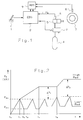
- FIG. 2 shows a diagram in which the braking pressures (P B ) of the wheels of the steering and front axles (VA) are plotted against the time (t).
- P B the braking pressures
- VA steering and front axles
- ABS (9) detects a tendency of the low wheel to lock and causes the brake pressure in the brake cylinder of the low wheel to drop, which continues until time t 2 .
- the brake pressure at time t 1 is the so-called cut-off pressure (P max ). This is followed by a pressure maintenance phase for the low wheel until a new control cycle begins at time (t 3 ) with a renewed pressure increase for the low wheel.
- the brake pressure in the high wheel continues to increase until it is reduced by the yaw moment weakening according to the invention at time (t 4 ), as soon as an average brake pressure difference ( ⁇ P) to the low wheel is reached, is kept constant.
- the increase in brake pressure can be delayed by appropriate signals from ABS (9) in order to slow the build-up of yaw moment at the start of braking.
- the regulated brake pressure difference ( ⁇ P) is not, as was previously the case, constant, but according to the invention essentially depends on the regulating pressures (P max ) of the regulating vehicle wheels, ie those vehicle wheels for which the ABS control is currently working (low wheels). This results in a variable behavior that takes into account both the road conditions and the vehicle weight. Tests and theoretical considerations have shown that the yaw moment that is permissible for the controllability of the vehicle and acts on the vehicle and thus the brake pressure difference ( ⁇ P) may be greater the greater the vehicle weight and the greater the coefficient of friction between the tire and the road surface.
- a brake pressure difference ⁇ P 1 is set in the period from t 4 to t 5 . From the period t 5 , when the road conditions have improved, which can be seen from the higher cut-off pressure P max of the low wheel, a higher brake pressure difference ⁇ P 2 is set. The braking pressure of the high wheel is increased accordingly.
- the brake pressure difference ( ⁇ P) is proportional to the cut-off pressure (P max ) of the low wheel. This has the advantage that the better utilization of the braking effect of the high wheel results in a shorter braking distance of the vehicle in better road conditions.
- ⁇ P permissible brake pressure difference
- P max the permissible brake pressure difference
- the permissible brake pressure difference ( ⁇ P) is formed proportionally to the quotient of the highest and the lowest control pressure (P max ) of the two wheels of the rear axle or drive axle.
- ⁇ P permissible brake pressure difference
- ⁇ P permissible brake pressure difference
- the relationships between the brake pressure difference ( ⁇ P) and the regulating pressure (P max ) described above can also be used as relationships to the average brake pressures of the regulating vehicle wheels, e.g. B. (P max and P min ) / 2 can be defined.
- the brake pressure of the high wheel of the steering axle is adjusted as the sum of the cut-off pressure (P max ) on the low wheel of the steering axle and the calculated brake pressure difference ( ⁇ P) (see Fig. 2).
- the braking pressure of the high wheel of the steering axle can also be adjusted as the sum of the respective braking pressure on the low wheel of the steering axle and the calculated brake pressure difference ( ⁇ P).
- the wheel load of the neighboring axle is reduced when the lift axle is lowered.
- the regulating pressures of the drive axle are also reduced. This would reduce the permitted brake pressure difference on the wheels of the steering axle in accordance with the methods presented above, although the vehicle has ⁇ -split friction values due to the lowered lift axle brakes more stable, so a higher brake pressure difference ⁇ P would be possible on the wheels of the steering axle without the vehicle becoming uncontrollable.
- This disadvantage can be countered expediently by recognizing a lowered lift axis by means of a suitable method. This can e.g. B. via a sensor, the values of which are transferred to the EBS or ABS electronics. This makes it possible to increase the value for the permissible brake pressure difference ( ⁇ P) on the wheels of the steering axle when the lift axle is recognized as lowered.
- the brake pressure difference can then be calculated according to one of the variants described above.
- the limitation on the rear axle is particularly useful for vehicles that are particularly unstable on ⁇ split lanes, such as. B. tractors of semitrailers that are driven without a trailer.
Landscapes
- Engineering & Computer Science (AREA)
- Transportation (AREA)
- Mechanical Engineering (AREA)
- Regulating Braking Force (AREA)
Applications Claiming Priority (2)
| Application Number | Priority Date | Filing Date | Title |
|---|---|---|---|
| DE19545001A DE19545001B4 (de) | 1995-12-02 | 1995-12-02 | Verfahren zur Giermoment-Abschwächung bei einem Antiblockiersystem |
| DE19545001 | 1995-12-02 |
Publications (4)
| Publication Number | Publication Date |
|---|---|
| EP0776806A2 true EP0776806A2 (fr) | 1997-06-04 |
| EP0776806A3 EP0776806A3 (fr) | 1999-03-17 |
| EP0776806B1 EP0776806B1 (fr) | 2002-05-02 |
| EP0776806B2 EP0776806B2 (fr) | 2005-01-19 |
Family
ID=7779023
Family Applications (1)
| Application Number | Title | Priority Date | Filing Date |
|---|---|---|---|
| EP96116734A Expired - Lifetime EP0776806B2 (fr) | 1995-12-02 | 1996-10-18 | Procédé d'amortissement du couple de fixation dans un système antiblocage |
Country Status (4)
| Country | Link |
|---|---|
| US (1) | US5944394A (fr) |
| EP (1) | EP0776806B2 (fr) |
| JP (1) | JP4151039B2 (fr) |
| DE (2) | DE19545001B4 (fr) |
Cited By (2)
| Publication number | Priority date | Publication date | Assignee | Title |
|---|---|---|---|---|
| EP2574513A1 (fr) * | 2011-09-28 | 2013-04-03 | Nissin Kogyo Co., Ltd. | Dispositif de commande de pression du fluide de freinage de véhicule |
| CN103029693A (zh) * | 2011-09-28 | 2013-04-10 | 日信工业株式会社 | 车辆用制动液压控制装置 |
Families Citing this family (18)
| Publication number | Priority date | Publication date | Assignee | Title |
|---|---|---|---|---|
| DE19732998A1 (de) | 1997-07-31 | 1999-02-04 | Itt Mfg Enterprises Inc | Verfahren und Vorrichtung zur Erkennung einer Bremssituation |
| US6663113B2 (en) | 1998-10-09 | 2003-12-16 | Robert Bosch Gmbh | System and method for reducing stopping distance and improving traction in motor vehicles |
| DE10011269A1 (de) * | 2000-03-08 | 2001-09-13 | Bosch Gmbh Robert | Verfahren und Vorrichtung zur Steuerung einer Bremsanlage |
| DE10053608B4 (de) * | 2000-10-28 | 2010-01-28 | Robert Bosch Gmbh | Antriebsschlupfregelungseinrichtung und Verfahren zum Regeln des Schlupfes eines Rades |
| JP4077613B2 (ja) * | 2001-05-30 | 2008-04-16 | トヨタ自動車株式会社 | 車輌用制動制御装置 |
| US7661772B2 (en) * | 2001-11-15 | 2010-02-16 | Robert Bosch Gmbh | Method and device for improving braking behavior |
| DE10207378B4 (de) * | 2001-11-15 | 2016-03-31 | Robert Bosch Gmbh | Verfahren und Vorrichtung zur Verbesserung des Bremsverhaltens |
| KR100774140B1 (ko) * | 2001-12-20 | 2007-11-08 | 주식회사 만도 | 요우레이트센서를 이용한 에이비에스 차량의 압력제어방법 |
| US20040201272A1 (en) * | 2003-04-08 | 2004-10-14 | Delphi Technologies Inc. | ABS yaw control with yaw rate sensor |
| DE10356673B4 (de) | 2003-12-04 | 2008-10-02 | Knorr-Bremse Systeme für Nutzfahrzeuge GmbH | Anordnung zur Beeinflussung des Giermoments |
| JP4701673B2 (ja) | 2004-10-22 | 2011-06-15 | トヨタ自動車株式会社 | ブレーキシステム |
| JP4705519B2 (ja) * | 2005-07-28 | 2011-06-22 | 日信工業株式会社 | 車両用ブレーキ圧制御装置 |
| DE102008001504A1 (de) * | 2008-04-30 | 2009-11-05 | Robert Bosch Gmbh | Vorrichtung und Verfahren zur Bremsdruckregelung |
| JP2012171404A (ja) * | 2011-02-18 | 2012-09-10 | Advics Co Ltd | アンチスキッド制御装置 |
| AT513370B1 (de) | 2013-11-05 | 2015-11-15 | Avl List Gmbh | Virtuelle Testoptimierung für Fahrerassistenzsysteme |
| DE102014216265A1 (de) * | 2014-08-15 | 2016-02-18 | Continental Teves Ag & Co. Ohg | Verfahren zur Anpassung der Regelstrategie eines Schlupfregelsystems eines Fahrzeugs in einer μ-Split-Situation |
| JP6984353B2 (ja) * | 2017-11-29 | 2021-12-17 | 株式会社アドヴィックス | 車両の制動制御装置 |
| EP4086125B1 (fr) * | 2021-05-06 | 2025-03-26 | Safran Landing Systems UK Ltd | Système de freinage antiblocage |
Citations (3)
| Publication number | Priority date | Publication date | Assignee | Title |
|---|---|---|---|---|
| DE2460309A1 (de) | 1974-12-20 | 1976-06-24 | Wabco Westinghouse Gmbh | Blockierschutzregelsystem fuer druckmittelbetaetigte fahrzeugbremsen |
| DE2855326A1 (de) | 1978-12-21 | 1980-07-17 | Wabco Fahrzeugbremsen Gmbh | Schaltungsanordnung zur verbesserung der fahrstabilitaet im bremsfalle bei fahrzeugen mit blockiergeschuetzten fahrzeugbremsanlagen |
| DE4406235A1 (de) | 1994-02-25 | 1995-08-31 | Wabco Vermoegensverwaltung | Druckregeleinrichtung |
Family Cites Families (8)
| Publication number | Priority date | Publication date | Assignee | Title |
|---|---|---|---|---|
| DE3626753A1 (de) * | 1986-08-07 | 1988-02-11 | Bosch Gmbh Robert | Fahrzeugbremsanlage |
| DE3919347C3 (de) * | 1988-06-15 | 2002-05-29 | Aisin Seiki | Einrichtung und Verfahren zur Regelung einer Fahrzeugbewegung |
| DE3925828C2 (de) * | 1989-08-04 | 1999-04-15 | Bosch Gmbh Robert | Antiblockierregelsystem |
| DE4012168C2 (de) * | 1990-04-14 | 1996-04-04 | Bosch Gmbh Robert | Antiblockierregelsystem |
| DE4034351A1 (de) † | 1990-10-29 | 1992-04-30 | Volkswagen Ag | Hydraulische bremsanlage fuer kraftfahrzeuge |
| DE4114734A1 (de) * | 1991-05-06 | 1992-11-12 | Teves Gmbh Alfred | Schaltungsanordnung fuer eine bremsanlage mit elektronischer blockierschutzregelung |
| DE4225983C2 (de) * | 1992-08-06 | 2002-03-14 | Bosch Gmbh Robert | Verfahren zur Bremsung von Fahrzeugrädern |
| JPH07132816A (ja) * | 1993-11-09 | 1995-05-23 | Akebono Brake Ind Co Ltd | アンチロック制御方法 |
-
1995
- 1995-12-02 DE DE19545001A patent/DE19545001B4/de not_active Expired - Lifetime
-
1996
- 1996-10-18 EP EP96116734A patent/EP0776806B2/fr not_active Expired - Lifetime
- 1996-10-18 DE DE59609148T patent/DE59609148D1/de not_active Expired - Lifetime
- 1996-11-22 JP JP35172996A patent/JP4151039B2/ja not_active Expired - Lifetime
- 1996-11-27 US US08/756,593 patent/US5944394A/en not_active Expired - Lifetime
Patent Citations (3)
| Publication number | Priority date | Publication date | Assignee | Title |
|---|---|---|---|---|
| DE2460309A1 (de) | 1974-12-20 | 1976-06-24 | Wabco Westinghouse Gmbh | Blockierschutzregelsystem fuer druckmittelbetaetigte fahrzeugbremsen |
| DE2855326A1 (de) | 1978-12-21 | 1980-07-17 | Wabco Fahrzeugbremsen Gmbh | Schaltungsanordnung zur verbesserung der fahrstabilitaet im bremsfalle bei fahrzeugen mit blockiergeschuetzten fahrzeugbremsanlagen |
| DE4406235A1 (de) | 1994-02-25 | 1995-08-31 | Wabco Vermoegensverwaltung | Druckregeleinrichtung |
Cited By (7)
| Publication number | Priority date | Publication date | Assignee | Title |
|---|---|---|---|---|
| EP2574513A1 (fr) * | 2011-09-28 | 2013-04-03 | Nissin Kogyo Co., Ltd. | Dispositif de commande de pression du fluide de freinage de véhicule |
| CN103029694A (zh) * | 2011-09-28 | 2013-04-10 | 日信工业株式会社 | 车辆用制动液压控制装置 |
| CN103029693A (zh) * | 2011-09-28 | 2013-04-10 | 日信工业株式会社 | 车辆用制动液压控制装置 |
| US8746814B2 (en) | 2011-09-28 | 2014-06-10 | Nissin Kogyo Co., Ltd. | Vehicle brake fluid pressure control apparatus |
| US8915554B2 (en) | 2011-09-28 | 2014-12-23 | Nissin Kogyo Co., Ltd. | Vehicle brake fluid pressure control apparatus |
| CN103029693B (zh) * | 2011-09-28 | 2014-12-31 | 日信工业株式会社 | 车辆用制动液压控制装置 |
| CN103029694B (zh) * | 2011-09-28 | 2015-03-04 | 日信工业株式会社 | 车辆用制动液压控制装置 |
Also Published As
| Publication number | Publication date |
|---|---|
| US5944394A (en) | 1999-08-31 |
| JP4151039B2 (ja) | 2008-09-17 |
| JPH09175367A (ja) | 1997-07-08 |
| EP0776806B1 (fr) | 2002-05-02 |
| DE19545001B4 (de) | 2005-03-24 |
| EP0776806B2 (fr) | 2005-01-19 |
| DE59609148D1 (de) | 2002-06-06 |
| DE19545001A1 (de) | 1997-06-05 |
| EP0776806A3 (fr) | 1999-03-17 |
Similar Documents
| Publication | Publication Date | Title |
|---|---|---|
| EP0776806B1 (fr) | Procédé d'amortissement du couple de fixation dans un système antiblocage | |
| EP0807562A2 (fr) | Procédé pour affaiblir le moment de giration dans un système antiblocage | |
| DE69019320T2 (de) | Verfahren und Vorrichtung zur Regelung des Knickwinkels bei Lastzügen. | |
| EP1334017B1 (fr) | Procede pour reguler la stabilite de conduite d'un vehicule | |
| EP2994355B1 (fr) | Procédé de freinage d'un ensemble véhicule tracteur-remorque avec une force de freinage de remorque réduite en fonction de la réaction du système abs du véhicule tracteur | |
| EP0339056B1 (fr) | Procede pour reguler la stabilite de vehicules | |
| EP1404553B1 (fr) | Procede permettant de modifier le systeme de regulation de la stabilite directionnelle d'un vehicule | |
| EP1414684B1 (fr) | Systeme de freinage pour remorques de vehicules utilitaires | |
| EP0844155B1 (fr) | Procédé de réduction de couple de lacet dans un véhicule ayant un système antiblocage. | |
| EP1758774B1 (fr) | Procede et dispositif pour stabiliser un vehicule | |
| DE10144299A1 (de) | Verfahren zur Fahrzustandsstabilisierung eines Nutzfahrzeugverbandes | |
| DE4226646A1 (de) | Bremsanlage | |
| DE10128357A1 (de) | Verfahren zur Regelung der Fahrstabilität | |
| DE10392719T5 (de) | Auf Antiblockierbremssystem beruhende Überschlagsverhinderung | |
| EP3322619A1 (fr) | Procédé et dispositif de régulation électronique d'un ralentissement d'un véhicule à régulation du glissement de freinage | |
| EP2049372B1 (fr) | Procédé de distribution de la pression de freinage aux essieux d'un véhicule | |
| EP1131235A1 (fr) | Procede et dispositif de stabilisation d'un vehicule equipe d'un systeme de freinage antiblocage de roues | |
| DE10119907B4 (de) | Verfahren zur Regelung der Fahrstabilität | |
| EP0443066B1 (fr) | Système de régulation de l'antiblocage du dispositif de freinage hydraulique d'un vehicule | |
| DE102010025363A1 (de) | Fahrzeugbewegungs-Steuerungseinrichtung | |
| DE19640229A1 (de) | Bremssteuerungssystem für ein Kraftfahrzeug | |
| DE10128690A1 (de) | Verfahren zur Regelung der Fahrstabilität | |
| DE102008046259A1 (de) | Verfahren und Vorrichtung zum Bestimmen einer Fahrstabilität eines Fahrzeugs beim Bremsen und Verfahren und Vorrichtung zum Einstellen eines Bremsdrucks für ein Fahrzeug | |
| EP0882631B1 (fr) | Procédé de freinage d'un véhicule | |
| EP1514755B1 (fr) | Procédé de commande de la pression d'entrée d'une valve de commande d'un système de freinage à anti-blocage |
Legal Events
| Date | Code | Title | Description |
|---|---|---|---|
| PUAI | Public reference made under article 153(3) epc to a published international application that has entered the european phase |
Free format text: ORIGINAL CODE: 0009012 |
|
| AK | Designated contracting states |
Kind code of ref document: A2 Designated state(s): DE FR IT SE |
|
| PUAL | Search report despatched |
Free format text: ORIGINAL CODE: 0009013 |
|
| AK | Designated contracting states |
Kind code of ref document: A3 Designated state(s): DE FR IT SE |
|
| 17P | Request for examination filed |
Effective date: 19990215 |
|
| RAP1 | Party data changed (applicant data changed or rights of an application transferred) |
Owner name: WABCO GMBH & CO. OHG |
|
| GRAG | Despatch of communication of intention to grant |
Free format text: ORIGINAL CODE: EPIDOS AGRA |
|
| 17Q | First examination report despatched |
Effective date: 20010710 |
|
| GRAG | Despatch of communication of intention to grant |
Free format text: ORIGINAL CODE: EPIDOS AGRA |
|
| GRAH | Despatch of communication of intention to grant a patent |
Free format text: ORIGINAL CODE: EPIDOS IGRA |
|
| GRAH | Despatch of communication of intention to grant a patent |
Free format text: ORIGINAL CODE: EPIDOS IGRA |
|
| GRAA | (expected) grant |
Free format text: ORIGINAL CODE: 0009210 |
|
| AK | Designated contracting states |
Kind code of ref document: B1 Designated state(s): DE FR IT SE |
|
| REF | Corresponds to: |
Ref document number: 59609148 Country of ref document: DE Date of ref document: 20020606 |
|
| ET | Fr: translation filed | ||
| PLBQ | Unpublished change to opponent data |
Free format text: ORIGINAL CODE: EPIDOS OPPO |
|
| PLBI | Opposition filed |
Free format text: ORIGINAL CODE: 0009260 |
|
| PLBF | Reply of patent proprietor to notice(s) of opposition |
Free format text: ORIGINAL CODE: EPIDOS OBSO |
|
| 26 | Opposition filed |
Opponent name: BAYERISCHE MOTORENWERKE AKTIENGESELLSCHAFT Effective date: 20030113 |
|
| PLBF | Reply of patent proprietor to notice(s) of opposition |
Free format text: ORIGINAL CODE: EPIDOS OBSO |
|
| PLAB | Opposition data, opponent's data or that of the opponent's representative modified |
Free format text: ORIGINAL CODE: 0009299OPPO |
|
| PLBQ | Unpublished change to opponent data |
Free format text: ORIGINAL CODE: EPIDOS OPPO |
|
| PUAH | Patent maintained in amended form |
Free format text: ORIGINAL CODE: 0009272 |
|
| STAA | Information on the status of an ep patent application or granted ep patent |
Free format text: STATUS: PATENT MAINTAINED AS AMENDED |
|
| R26 | Opposition filed (corrected) |
Opponent name: BAYERISCHE MOTORENWERKE AKTIENGESELLSCHAFT Effective date: 20030113 |
|
| 27A | Patent maintained in amended form |
Effective date: 20050119 |
|
| AK | Designated contracting states |
Kind code of ref document: B2 Designated state(s): DE FR IT SE |
|
| REG | Reference to a national code |
Ref country code: SE Ref legal event code: RPEO |
|
| ET3 | Fr: translation filed ** decision concerning opposition | ||
| REG | Reference to a national code |
Ref country code: FR Ref legal event code: PLFP Year of fee payment: 20 |
|
| PGFP | Annual fee paid to national office [announced via postgrant information from national office to epo] |
Ref country code: IT Payment date: 20151012 Year of fee payment: 20 Ref country code: DE Payment date: 20151031 Year of fee payment: 20 |
|
| PGFP | Annual fee paid to national office [announced via postgrant information from national office to epo] |
Ref country code: FR Payment date: 20151023 Year of fee payment: 20 Ref country code: SE Payment date: 20151006 Year of fee payment: 20 |
|
| REG | Reference to a national code |
Ref country code: DE Ref legal event code: R071 Ref document number: 59609148 Country of ref document: DE |
|
| REG | Reference to a national code |
Ref country code: SE Ref legal event code: EUG |