EP0777105B1 - Vibrationskreisel und Verfahren zur Einstellung seiner Eigenschaften - Google Patents
Vibrationskreisel und Verfahren zur Einstellung seiner Eigenschaften Download PDFInfo
- Publication number
- EP0777105B1 EP0777105B1 EP96118723A EP96118723A EP0777105B1 EP 0777105 B1 EP0777105 B1 EP 0777105B1 EP 96118723 A EP96118723 A EP 96118723A EP 96118723 A EP96118723 A EP 96118723A EP 0777105 B1 EP0777105 B1 EP 0777105B1
- Authority
- EP
- European Patent Office
- Prior art keywords
- detecting element
- impedance
- load
- matching condition
- vibration
- Prior art date
- Legal status (The legal status is an assumption and is not a legal conclusion. Google has not performed a legal analysis and makes no representation as to the accuracy of the status listed.)
- Expired - Lifetime
Links
Images



Classifications
-
- G—PHYSICS
- G01—MEASURING; TESTING
- G01C—MEASURING DISTANCES, LEVELS OR BEARINGS; SURVEYING; NAVIGATION; GYROSCOPIC INSTRUMENTS; PHOTOGRAMMETRY OR VIDEOGRAMMETRY
- G01C19/00—Gyroscopes; Turn-sensitive devices using vibrating masses; Turn-sensitive devices without moving masses; Measuring angular rate using gyroscopic effects
- G01C19/56—Turn-sensitive devices using vibrating masses, e.g. vibratory angular rate sensors based on Coriolis forces
-
- G—PHYSICS
- G01—MEASURING; TESTING
- G01C—MEASURING DISTANCES, LEVELS OR BEARINGS; SURVEYING; NAVIGATION; GYROSCOPIC INSTRUMENTS; PHOTOGRAMMETRY OR VIDEOGRAMMETRY
- G01C19/00—Gyroscopes; Turn-sensitive devices using vibrating masses; Turn-sensitive devices without moving masses; Measuring angular rate using gyroscopic effects
- G01C19/56—Turn-sensitive devices using vibrating masses, e.g. vibratory angular rate sensors based on Coriolis forces
- G01C19/5642—Turn-sensitive devices using vibrating masses, e.g. vibratory angular rate sensors based on Coriolis forces using vibrating bars or beams
- G01C19/5649—Signal processing
-
- G—PHYSICS
- G01—MEASURING; TESTING
- G01C—MEASURING DISTANCES, LEVELS OR BEARINGS; SURVEYING; NAVIGATION; GYROSCOPIC INSTRUMENTS; PHOTOGRAMMETRY OR VIDEOGRAMMETRY
- G01C19/00—Gyroscopes; Turn-sensitive devices using vibrating masses; Turn-sensitive devices without moving masses; Measuring angular rate using gyroscopic effects
Definitions
- the present invention relates to a vibration gyroscope and a method for adjusting the characteristics of the same, and more particularly, to a vibration gyroscope having a detecting device for obtaining a signal corresponding to a rotation angular velocity and a method for adjusting the characteristics of the same.
- FIG. 6 is a diagram showing an example of a conventional vibration gyroscope.
- a vibration gyroscope 1 shown in Fig. 6 includes a vibrator 2.
- the vibrator 2 includes a vibration member 3 having a regular triangular prism shape.
- the vibration member 3 is made from, for example, permanently elastic metal materials such as elinvar.
- three piezoelectric elements 4a, 4b, and 4c are formed, respectively.
- These piezoelectric elements 4a to 4c each include a piezoelectric layer made up of ceramic.
- Each piezoelectric element is provided with electrodes at both primary surfaces of the piezoelectric layer.
- One electrode on a primary surface of the piezoelectric layer is adhered to a side face of the vibration member and the other electrode, which is disposed on the other primary surface of the piezoelectric layer, is used for signal input and output.
- two piezoelectric elements 4a and 4b are used for feedback and detection, and the other piezoelectric element 4c is used for driving.
- Two piezoelectric elements 4a and 4b are connected to the input terminal of an oscillation circuit 6 through resistors 5a and 5b which serve as the loads of the piezoelectric elements.
- the impedances of the resistors 5a and 5b are set equal to the impedances of piezoelectric element 4a and 4b, which serve as detecting elements, in a matching condition, respectively.
- the output terminal of the oscillation circuit 6 is connected to piezoelectric element 4c.
- Piezoelectric elements 4a and 4b are connected to the non-inverting input terminal and the inverting input terminal of a differential amplifier circuit 7, respectively.
- the output terminal of the differential amplifier circuit 7 is connected to the input terminal of a synchronous- detection circuit 8.
- the output terminal of the synchronous-detection circuit 8 is connected to the input terminal of a smoothing circuit 9.
- the signal output from the differential amplifier circuit 7 is synchronously detected by the synchronous-detection circuit 8, and the output signal of the synchronous-detection circuit 8 is smoothed by the smoothing circuit 9. Therefore, the rotation angular velocity is detected from the output signal of the smoothing circuit 9 in this vibration gyroscope 1.
- the relationship between temperature and sensitivity change rate without any compensation are determined by the temperature characteristics of the ceramic in the piezoelectric layers of piezoelectric elements 4a and 4b, which serve as detecting elements.
- the level of a driving signal is changed with the use of a thermistor or diode in a driving-signal processing system including the oscillation circuit 6.
- the gain of a detected signal is changed with the use of a thermistor or diode in a detected-signal processing system including the differential amplifier circuit 7, the synchronous-detection circuit 8, and the smoothing circuit 9.
- the cost of the vibration gyroscope increases due to high cost of the thermistor or diode, and the number of used components also increases.
- the vibration frequency of the vibrator is increased or the vibrator material is changed.
- the size and the shape of the vibrator need to be changed and changes of the circuit constants in the peripheral circuits are also required. These factors cause high cost.
- the vibrator needs to be changed and changes of the circuit constants in the peripheral circuits are also required. These factors also increase cost.
- U.S. Patent No. 4,791,815 discloses a cyclically driven gyro having a tuning fork structure portion, on which two rectangular piezoelectric elements are secured. Each of the rectangular piezoelectric elements is fixed to a cantilever supported at a joint with the tuning fork structure portion. The tuning fork structure portion is excited by a drive circuit. Each of the piezoelectric elements is connected to a preamplifier for converting the capacitive, high input impedance outputs of the piezoelectric elements into low output impedance voltage signals. The output signals of each preamplifier are added and the added signal is input into a signal processing circuit for obtaining an output signal indicative of an angular rate applied to the tuning fork structure portion.
- Another object of the present invention is to provide an inexpensive, good-response vibration gyroscope.
- Still another object of the present invention is to provide a method for inexpensively adjusting the characteristics of a vibration gyroscope.
- the impedance of the loads is made lower than the impedance of the detecting elements in a matching condition to improve the response of the vibration gyroscope.
- the impedance of the loads is made higher than the impedance of the detecting elements in a matching condition to improve the response of the vibration gyroscope.
- the desired response is a desired relationship between temperature and sensitivity change rate.
- a thermistor or diode is not required to obtain the desired relationship between temperature and sensitivity change rate, decreasing the cost of the vibration gyroscope. Additionally, it is not necessary to increase the vibration frequency of the vibrator or to change the vibrator material, in order to improve the response. Thus, further reducing the cost of the vibration gyroscope.
- a method for adjusting the characteristics of a vibration gyroscope which has at least a first detecting element for obtaining a signal corresponding to a rotation angular velocity, including the step of connecting at least a first load to the first detecting element, the impedance of the first load being different than the impedance of the first detecting element and having a value commensurate with a desired response.
- the vibrator includes a second detection element
- the method further includes connecting a second load to the second detection element, the impedance of the second load being different than the impedance of the second detection element and having a value commensurate with a desired response.
- a thermistor or a diode is not required, and it is not necessary to increase the vibration frequency of the vibrator or to change the vibrator material, in order to improve the response.
- the cost of the vibration gyroscope is reduced.
- an inexpensive, good-response vibration gyroscope is also obtained.
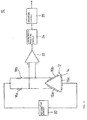
- FIG. 1 is diagram showing a vibration gyroscope according to an embodiment of the present invention.
- a vibration gyroscope 10 shown in Fig. 1 includes a vibrator 12.
- the vibrator 12 has a vibration member 14 which is formed, for example, in a regular triangular prism shape.
- the vibration member 14 is formed, for example, by permanently elastic metal materials, such as elinvar and an iron-nickel alloy.
- piezoelectric elements 16a, 16b, and 16c are formed, respectively.
- These piezoelectric elements 16a to 16c each include a piezoelectric layer made up of ceramic.
- Each piezoelectric element is provided with electrodes at both primary surfaces of the piezoelectric layer.
- One electrode on a primary surface of the piezoelectric layer is adhered to a side face of the vibration member 14 and the other electrode, which is disposed on the other primary surface of the piezoelectric layer, is used for signal input and output.
- two piezoelectric elements 16a and 16b are used for feedback and detection, and the other piezoelectric element 16c is used for driving.
- Two piezoelectric elements 16a and 16b are connected to the input terminal of an oscillation circuit 20 through resistors 18a and 18b which serve as the loads of the piezoelectric elements.
- the output terminal of the oscillation circuit 20 is connected to piezoelectric element 16c.
- Two piezoelectric elements 16a and 16b are also connected to the non-inverting input terminal and the inverting input terminal of a differential amplifier circuit 22, respectively.
- the output terminal of the differential amplifier circuit 22 is connected to the input terminal of a synchronous-detection circuit 24.
- the output terminal of the synchronous-detection circuit 24 is connected to the input terminal of a smoothing circuit 26.
- the signal output from the differential amplifier circuit 22 is synchronously detected by the synchronous-detection circuit 24, and the output signal of the synchronous-detection circuit 24 is smoothed by the smoothing circuit 26. Therefore, the rotation angular velocity is detected from the output signal of the smoothing circuit 26 in this vibration gyroscope 10.
- the desired relationship between temperature and sensitivity change rate can be obtained by differentiating the impedances of the resistors 18a and 18b from those of piezoelectric elements 16a and 16b in a matching condition. The details will be described below.
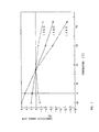
- Fig. 2 shows the relationship between temperature and sensitivity change rate at 25°C with sensitivity being used as a reference in the vibration gyroscope 10 with the impedances of piezoelectric elements 16a and 16b in a matching condition being set to 15 k ⁇ and those of the resistors 18a and 18b being set to 12, 15, or 18 k ⁇ .
- the impedances of the resistors 18a and 18b are set to the same (15 k ⁇ ) as those of piezoelectric elements 16a and 16b in a matching condition, the relationship between temperature and sensitivity change rate has a negative gradient.
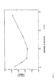
- Fig. 3 shows the phase lag of the signal output from the smoothing circuit 26 against the rotation angular velocity in the vibration gyroscope 10 with a rotation angular velocity of 30 Hz being applied and with the impedances of piezoelectric elements 16a and 16b in a matching condition being set to 15 k ⁇ and those of the resistors 18a and 18b being set to 5.6 to 33 k ⁇ .
- the impedances of the resistors 18a and 18b are set to the same as those (15 k ⁇ ) of piezoelectric elements 16a and 16b in a matching condition, the phase lag of the output signal is large.
- the impedances of the resistors 18a and 18b are set to smaller or larger than those (15 k ⁇ ) of piezoelectric elements 16a and 16b in a matching condition, the phase lag of the output signal becomes small.
- Fig. 4 shows the sensitivity change rate of the vibration gyroscope 10 with the impedances of piezoelectric elements 16a and 16b in a matching condition being set to 15 k ⁇ and those of the resistors 18a and 18b being set to 15 to 33 k ⁇ .
- the impedances of the resistors 18a and 18b are set to larger than those (15 k ⁇ ) of piezoelectric elements 16a and 16b in a matching condition, the detecting sensitivity of the vibrator increases and the S/N ratio is improved.
- two piezoelectric elements 16a and 16b are used for feedback and detection, and the other piezoelectric element 16c is used for driving.
- the vibration gyroscope may be configured such that two piezoelectric elements 16a and 16b serve as driving means and detecting means and the other piezoelectric element 16c is used as feedback means.
- the piezoelectric element 16c is connected to the input terminal of the oscillation circuit 20, and the output terminal of the oscillation circuit 20 is connected to piezoelectric elements 16a and 16b through resistors 18a and 18b which serve as the loads of piezoelectric elements 16a and 16b.
- Two piezoelectric elements 16a and 16b are also connected to the non-inverting input terminal and the inverting input terminal of the differential amplifier circuit 22, respectively.
- the output terminal of the differential amplifier circuit 22 is connected to the input terminal of the synchronous-detection circuit 24, and the output terminal of the synchronous-detection circuit 24 is connected to the input terminal of the smoothing circuit 26.
- a vibration member having a regular triangular prism shape is used.
- the vibration member may have another prism shape such as a cylindrical shape and a quadrangular prism shape.
- three piezoelectric elements are used. Only two piezoelectric elements for driving and detection may be used. The number of piezoelectric elements used can be changed.
Landscapes
- Engineering & Computer Science (AREA)
- Physics & Mathematics (AREA)
- General Physics & Mathematics (AREA)
- Radar, Positioning & Navigation (AREA)
- Remote Sensing (AREA)
- Signal Processing (AREA)
- Gyroscopes (AREA)
Claims (7)
- Ein Vibrationsgyroskop (10), das folgende Merkmale aufweist:dadurch gekennzeichnet, daßein Schwingungselement (12), das ein erstes Erfassungselement (16a) und ein zweites Erfassungselement (16b) zum Erhalten eines Signals aufweist, das einer Rotationswinkelgeschwindigkeit entspricht, wobei das erste Erfassungselement (16a) eine Impedanz aufweist und das zweite Erfassungselement eine Impedanz aufweist;eine erste Last (18a), die eine Impedanz aufweist, wobei die erste Last zwischen das erste Erfassungselement (16a) und einer Oszillationsschaltung (20) zum Erzeugen eines Treibersignals zum Treiben des Schwingungselements (12) geschaltet ist, wobei das Treibersignal eine Treiberfrequenz aufweist;eine zweite Last (18b), die eine Impedanz aufweist, wobei die zweite Last zwischen das zweite Erfassungselement (16b) und die Oszillationsschaltung (20) geschaltet ist; undbei dem die Impedanz des ersten Erfassungselements (16a) in einem Anpassungszustand durch eine Kapazität des ersten Erfassungselements (16a) und die Treiberfrequenz bestimmt wird, und bei dem die Impedanz des zweiten Erfassungselements (16b) in einem Anpassungszustand durch eine Kapazität des zweiten Erfassungselements (16b) und die Treiberfrequenz bestimmt wird;die Impedanz der ersten Last (18a) sich von der Impedanz des ersten Erfassungselements (16a) in einem Anpassungszustand unterscheidet,die Impedanz der zweiten Last (18b) sich von der Impedanz des zweiten Erfassungselements (16b) in einem Anpassungszustand unterscheidet, unddie erste und zweite Lastimpedanz Werte aufweisen, die ausgewählt werden, um ein gewünschtes Verhältnis zwischen Temperatur und Empfindlichkeitsänderungsrate, eine erhöhte Erfassungsempfindlichkeit oder ein gewünschtes Ansprechverhalten zu erreichen.
- Ein Vibrationsgyroskop (10) gemäß Anspruch 1, bei dem die Impedanz der ersten Last (18a) und die Impedanz der zweiten Last (18b) geringer sind als die jeweiligen Impedanzen des ersten Erfassungselements (16a) und des zweiten Erfassungselements (16b) in einem Anpassungszustand.
- Ein Vibrationsgyroskop (10) gemäß Anspruch 1, bei dem die Impedanz der ersten Last (18a) und die Impedanz der zweiten Last (18b) höher sind als die jeweiligen Impedanzen des ersten Erfassungselements (16a) und des zweiten Erfassungselements (16b) in einem Anpassungszustand.
- Ein Vibrationsgyroskop gemäß Anspruch 5, bei dem die erste und die zweite Last (18a, 18b) erste und zweite Widerstände sind.
- Ein Verfahren zum Einstellen von Charakteristika eines Vibrationsgyroskops (10), das ein Schwingungselement aufweist, das ein erstes Erfassungselement (16a) und ein zweites Erfassungselement (16b) aufweist, wobei das erste Erfassungselement (16a) eine Impedanz aufweist und das zweite Erfassungselement eine Impedanz aufweist, zum Erhalten eines Signals, das einer Rotationswinkelgeschwindigkeit entspricht, wobei das Verfahren folgende Schritte aufweist:dadurch gekennzeichnet, daßSchalten einer ersten Last (18a), die eine Impedanz aufweist, zwischen das erste Erfassungselement (16a) und eine Oszillationsschaltung (20) aufweist, zum Erzeugen eines Treibersignals zum Treiben des Schwingungselements (12), wobei das Treibersignal eine Treiberfrequenz aufweist; undSchalten einer zweiten Last (18b), die eine Impedanz aufweist, zwischen das zweite Erfassungselement (16b) und die Oszillationsschaltung (20); undbei dem die Impedanz des ersten Erfassungselements (16a) in einem Anpassungszustand durch eine Kapazität des ersten Erfassungselements (16a) und die Treiberfrequenz bestimmt wird, und bei dem die Impedanz des zweiten Erfassungselements (16b) in einem Anpassungszustand durch eine Kapazität des zweiten Erfassungselements (16b) und die Treiberfrequenz bestimmt wird;die Impedanz der ersten Last (18a) sich von der Impedanz des ersten Erfassungselements (16a) in einem Anpassungszustand unterscheidet,die Impedanz der zweiten Last (18b) sich von der Impedanz des zweiten Erfassungselements (16b) in einem Anpassungszustand unterscheidet, unddie erste und zweite Lastimpedanz Werte aufweisen, die ausgewählt werden, um ein gewünschtes Verhältnis zwischen Temperatur und Empfindlichkeitsänderungsrate, eine erhöhte Erfassungsempfindlichkeit oder ein gewünschtes Ansprechverhalten zu erreichen.
- Verfahren gemäß Anspruch 5, bei dem die Impedanzen der ersten Last (18a) und der zweiten Last (18b) geringer sind als die jeweiligen Impedanzen des ersten Erfassungselements (16a) und des zweiten Erfassungselements (16b) in einem Anpassungszustand.
- Verfahren gemäß Anspruch 5, bei dem die Impedanz der ersten Last (18a) und die Impedanz der zweiten Last (18b) höher sind als die jeweiligen Impedanzen des ersten Erfassungselements (16a) und des zweiten Erfassungselements (16b) in einem Anpassungszustand.
Applications Claiming Priority (3)
| Application Number | Priority Date | Filing Date | Title |
|---|---|---|---|
| JP7328352A JP3039344B2 (ja) | 1995-11-22 | 1995-11-22 | 振動ジャイロおよび振動ジャイロの特性の調整方法 |
| JP328352/95 | 1995-11-22 | ||
| JP32835295 | 1995-11-22 |
Publications (3)
| Publication Number | Publication Date |
|---|---|
| EP0777105A2 EP0777105A2 (de) | 1997-06-04 |
| EP0777105A3 EP0777105A3 (de) | 1998-07-01 |
| EP0777105B1 true EP0777105B1 (de) | 2002-10-23 |
Family
ID=18209290
Family Applications (1)
| Application Number | Title | Priority Date | Filing Date |
|---|---|---|---|
| EP96118723A Expired - Lifetime EP0777105B1 (de) | 1995-11-22 | 1996-11-21 | Vibrationskreisel und Verfahren zur Einstellung seiner Eigenschaften |
Country Status (5)
| Country | Link |
|---|---|
| US (1) | US5922954A (de) |
| EP (1) | EP0777105B1 (de) |
| JP (1) | JP3039344B2 (de) |
| KR (1) | KR100210334B1 (de) |
| DE (1) | DE69624448T2 (de) |
Families Citing this family (3)
| Publication number | Priority date | Publication date | Assignee | Title |
|---|---|---|---|---|
| JP4572350B2 (ja) * | 2008-03-21 | 2010-11-04 | セイコーエプソン株式会社 | 同期検波回路、検出回路、物理量測定装置、ジャイロセンサおよび電子機器 |
| JP5578176B2 (ja) * | 2009-05-27 | 2014-08-27 | パナソニック株式会社 | 物理量センサ |
| CN103759743B (zh) * | 2014-01-29 | 2016-08-24 | 西安航天精密机电研究所 | 惯性测量装置方位基准传递装置及大倾角时方位确定方法 |
Family Cites Families (8)
| Publication number | Priority date | Publication date | Assignee | Title |
|---|---|---|---|---|
| US4694696A (en) * | 1984-10-25 | 1987-09-22 | Kabushikikaisha Tokyo Keiki | Vibration-type gyro apparatus |
| JPS6410112A (en) * | 1987-07-02 | 1989-01-13 | Hitachi Metals Ltd | Dimension measuring instrument for centerless grinder |
| JPH0310112A (ja) * | 1989-06-08 | 1991-01-17 | Tokimec Inc | ジャイロ装置 |
| DE69111950T2 (de) * | 1990-08-27 | 1996-03-14 | Murata Manufacturing Co | Signaldetektorschaltung für Schwingkreisel. |
| JPH0552572A (ja) * | 1991-08-28 | 1993-03-02 | Akai Electric Co Ltd | 振動子の支持構造 |
| JPH0571967A (ja) * | 1991-09-17 | 1993-03-23 | Akai Electric Co Ltd | 振動ジヤイロ |
| JP3232638B2 (ja) * | 1992-04-07 | 2001-11-26 | 日産自動車株式会社 | 圧電式振動ジャイロの直流増幅回路 |
| JPH0783670A (ja) * | 1993-09-16 | 1995-03-28 | Murata Mfg Co Ltd | 圧電振動子の駆動・検出回路 |
-
1995
- 1995-11-22 JP JP7328352A patent/JP3039344B2/ja not_active Expired - Lifetime
-
1996
- 1996-11-21 US US08/754,704 patent/US5922954A/en not_active Expired - Lifetime
- 1996-11-21 DE DE69624448T patent/DE69624448T2/de not_active Expired - Lifetime
- 1996-11-21 EP EP96118723A patent/EP0777105B1/de not_active Expired - Lifetime
- 1996-11-22 KR KR1019960056631A patent/KR100210334B1/ko not_active Expired - Lifetime
Also Published As
| Publication number | Publication date |
|---|---|
| JP3039344B2 (ja) | 2000-05-08 |
| US5922954A (en) | 1999-07-13 |
| JPH09145380A (ja) | 1997-06-06 |
| DE69624448D1 (de) | 2002-11-28 |
| KR100210334B1 (ko) | 1999-07-15 |
| KR970028442A (ko) | 1997-06-24 |
| DE69624448T2 (de) | 2003-03-20 |
| EP0777105A2 (de) | 1997-06-04 |
| EP0777105A3 (de) | 1998-07-01 |
Similar Documents
| Publication | Publication Date | Title |
|---|---|---|
| US4654663A (en) | Angular rate sensor system | |
| GB2158579A (en) | Angular rate sensor system | |
| WO1994011706A1 (fr) | Circuit detecteur de velocite angulaire | |
| JPH063455B2 (ja) | 振動ジャイロ | |
| US20020100322A1 (en) | Vibrating gyroscope and temperature-drift adjusting method therefor | |
| KR100254114B1 (ko) | 2축 동시 측정용 압전 회전 센서 및 그 측정 회로 | |
| JPH0545167A (ja) | 振動ジヤイロ | |
| CA2203849C (en) | Vibration gyroscope | |
| EP0647831A1 (de) | Treiber- und Signaldetektorschaltung für Schwingkreisel | |
| US5922954A (en) | Vibration gyroscope and method for adjusting vibration-gyroscope characteristics | |
| EP0834719B1 (de) | Verfahren zum Einstellen der Temperaturcharakteristik einse Vibrationskreisels | |
| EP0635699B1 (de) | Detektionsschaltung | |
| EP0645602B1 (de) | Vibratordrehungsmessaufnehmer | |
| JP2508264B2 (ja) | 振動ジャイロ | |
| JPH07167661A (ja) | 振動ジャイロ | |
| JPH09159459A (ja) | 振動ジャイロ | |
| JPH08278141A (ja) | セラミック圧電複合形角速度センサ | |
| US5850119A (en) | Vibration gyroscope | |
| JPH07270165A (ja) | 振動ジャイロ装置 | |
| JPH08338729A (ja) | 自励振回路及びこれを用いた圧電振動角速度計 | |
| JPH09292231A (ja) | 振動ジャイロ | |
| JP2620007B2 (ja) | 振動ジャイロ用振動子 | |
| JPH07332989A (ja) | 振動ジャイロの駆動回路 | |
| JP2002372420A (ja) | 振動ジャイロの駆動検出回路 | |
| JPH07151551A (ja) | 振動ジャイロ装置 |
Legal Events
| Date | Code | Title | Description |
|---|---|---|---|
| PUAI | Public reference made under article 153(3) epc to a published international application that has entered the european phase |
Free format text: ORIGINAL CODE: 0009012 |
|
| 17P | Request for examination filed |
Effective date: 19961121 |
|
| AK | Designated contracting states |
Kind code of ref document: A2 Designated state(s): DE FR GB |
|
| PUAL | Search report despatched |
Free format text: ORIGINAL CODE: 0009013 |
|
| AK | Designated contracting states |
Kind code of ref document: A3 Designated state(s): DE FR GB |
|
| 17Q | First examination report despatched |
Effective date: 20000807 |
|
| GRAG | Despatch of communication of intention to grant |
Free format text: ORIGINAL CODE: EPIDOS AGRA |
|
| GRAG | Despatch of communication of intention to grant |
Free format text: ORIGINAL CODE: EPIDOS AGRA |
|
| GRAH | Despatch of communication of intention to grant a patent |
Free format text: ORIGINAL CODE: EPIDOS IGRA |
|
| GRAH | Despatch of communication of intention to grant a patent |
Free format text: ORIGINAL CODE: EPIDOS IGRA |
|
| GRAA | (expected) grant |
Free format text: ORIGINAL CODE: 0009210 |
|
| AK | Designated contracting states |
Kind code of ref document: B1 Designated state(s): DE FR GB |
|
| REG | Reference to a national code |
Ref country code: GB Ref legal event code: FG4D |
|
| REF | Corresponds to: |
Ref document number: 69624448 Country of ref document: DE Date of ref document: 20021128 |
|
| ET | Fr: translation filed | ||
| PLBE | No opposition filed within time limit |
Free format text: ORIGINAL CODE: 0009261 |
|
| STAA | Information on the status of an ep patent application or granted ep patent |
Free format text: STATUS: NO OPPOSITION FILED WITHIN TIME LIMIT |
|
| 26N | No opposition filed |
Effective date: 20030724 |
|
| REG | Reference to a national code |
Ref country code: FR Ref legal event code: PLFP Year of fee payment: 20 |
|
| PGFP | Annual fee paid to national office [announced via postgrant information from national office to epo] |
Ref country code: GB Payment date: 20151118 Year of fee payment: 20 Ref country code: DE Payment date: 20151119 Year of fee payment: 20 |
|
| PGFP | Annual fee paid to national office [announced via postgrant information from national office to epo] |
Ref country code: FR Payment date: 20151119 Year of fee payment: 20 |
|
| REG | Reference to a national code |
Ref country code: DE Ref legal event code: R071 Ref document number: 69624448 Country of ref document: DE |
|
| REG | Reference to a national code |
Ref country code: GB Ref legal event code: PE20 Expiry date: 20161120 |
|
| PG25 | Lapsed in a contracting state [announced via postgrant information from national office to epo] |
Ref country code: GB Free format text: LAPSE BECAUSE OF EXPIRATION OF PROTECTION Effective date: 20161120 |