EP0777284A1 - Elektroden aus einer Wasserstoff-absorbierenden Legierung - Google Patents
Elektroden aus einer Wasserstoff-absorbierenden Legierung Download PDFInfo
- Publication number
- EP0777284A1 EP0777284A1 EP96119634A EP96119634A EP0777284A1 EP 0777284 A1 EP0777284 A1 EP 0777284A1 EP 96119634 A EP96119634 A EP 96119634A EP 96119634 A EP96119634 A EP 96119634A EP 0777284 A1 EP0777284 A1 EP 0777284A1
- Authority
- EP
- European Patent Office
- Prior art keywords
- hydrogen absorbing
- alloy
- absorbing alloy
- particles
- electrode
- Prior art date
- Legal status (The legal status is an assumption and is not a legal conclusion. Google has not performed a legal analysis and makes no representation as to the accuracy of the status listed.)
- Granted
Links
- 239000000956 alloy Substances 0.000 title claims abstract description 529
- 229910045601 alloy Inorganic materials 0.000 title claims abstract description 528
- 239000001257 hydrogen Substances 0.000 title claims abstract description 248
- 229910052739 hydrogen Inorganic materials 0.000 title claims abstract description 248
- UFHFLCQGNIYNRP-UHFFFAOYSA-N Hydrogen Chemical compound [H][H] UFHFLCQGNIYNRP-UHFFFAOYSA-N 0.000 title claims abstract description 247
- 239000000203 mixture Substances 0.000 claims abstract description 85
- 239000002245 particle Substances 0.000 claims abstract description 73
- 229910001068 laves phase Inorganic materials 0.000 claims abstract description 19
- 229910003126 Zr–Ni Inorganic materials 0.000 claims abstract description 17
- 238000005245 sintering Methods 0.000 claims description 48
- 238000005551 mechanical alloying Methods 0.000 claims description 37
- 239000013078 crystal Substances 0.000 claims description 22
- 238000011049 filling Methods 0.000 claims description 6
- 239000000758 substrate Substances 0.000 claims description 5
- 230000004913 activation Effects 0.000 description 61
- 230000000052 comparative effect Effects 0.000 description 41
- 239000000843 powder Substances 0.000 description 34
- PXHVJJICTQNCMI-UHFFFAOYSA-N Nickel Chemical compound [Ni] PXHVJJICTQNCMI-UHFFFAOYSA-N 0.000 description 22
- 238000012360 testing method Methods 0.000 description 19
- 238000000465 moulding Methods 0.000 description 18
- KWYUFKZDYYNOTN-UHFFFAOYSA-M Potassium hydroxide Chemical compound [OH-].[K+] KWYUFKZDYYNOTN-UHFFFAOYSA-M 0.000 description 12
- 239000003513 alkali Substances 0.000 description 11
- 238000000034 method Methods 0.000 description 11
- 238000002156 mixing Methods 0.000 description 11
- 229910052759 nickel Inorganic materials 0.000 description 11
- 238000004458 analytical method Methods 0.000 description 7
- 238000004453 electron probe microanalysis Methods 0.000 description 7
- 230000007423 decrease Effects 0.000 description 6
- 229920001343 polytetrafluoroethylene Polymers 0.000 description 6
- 239000004810 polytetrafluoroethylene Substances 0.000 description 6
- 238000002360 preparation method Methods 0.000 description 6
- 239000007864 aqueous solution Substances 0.000 description 5
- 239000003245 coal Substances 0.000 description 5
- 230000000694 effects Effects 0.000 description 5
- 239000003792 electrolyte Substances 0.000 description 5
- 238000004519 manufacturing process Methods 0.000 description 5
- 239000011230 binding agent Substances 0.000 description 4
- 239000002131 composite material Substances 0.000 description 4
- -1 polytetrafluoroethylene Polymers 0.000 description 4
- 239000012300 argon atmosphere Substances 0.000 description 3
- 238000007664 blowing Methods 0.000 description 3
- 239000004745 nonwoven fabric Substances 0.000 description 3
- 230000002195 synergetic effect Effects 0.000 description 3
- 229910001122 Mischmetal Inorganic materials 0.000 description 2
- 239000011248 coating agent Substances 0.000 description 2
- 238000000576 coating method Methods 0.000 description 2
- 229910052751 metal Inorganic materials 0.000 description 2
- 239000002184 metal Substances 0.000 description 2
- 229910052761 rare earth metal Inorganic materials 0.000 description 2
- IJGRMHOSHXDMSA-UHFFFAOYSA-N Atomic nitrogen Chemical compound N#N IJGRMHOSHXDMSA-UHFFFAOYSA-N 0.000 description 1
- 229910000990 Ni alloy Inorganic materials 0.000 description 1
- 239000004743 Polypropylene Substances 0.000 description 1
- 229910010969 Ti—V—Ni Inorganic materials 0.000 description 1
- 238000010521 absorption reaction Methods 0.000 description 1
- 239000000919 ceramic Substances 0.000 description 1
- 238000006243 chemical reaction Methods 0.000 description 1
- 238000010276 construction Methods 0.000 description 1
- 238000003795 desorption Methods 0.000 description 1
- 238000010586 diagram Methods 0.000 description 1
- 229910001873 dinitrogen Inorganic materials 0.000 description 1
- 150000002431 hydrogen Chemical class 0.000 description 1
- 239000011261 inert gas Substances 0.000 description 1
- 229920001155 polypropylene Polymers 0.000 description 1
- 230000002035 prolonged effect Effects 0.000 description 1
- 238000010298 pulverizing process Methods 0.000 description 1
- 238000004080 punching Methods 0.000 description 1
Images





Classifications
-
- H—ELECTRICITY
- H01—ELECTRIC ELEMENTS
- H01M—PROCESSES OR MEANS, e.g. BATTERIES, FOR THE DIRECT CONVERSION OF CHEMICAL ENERGY INTO ELECTRICAL ENERGY
- H01M4/00—Electrodes
- H01M4/02—Electrodes composed of, or comprising, active material
- H01M4/36—Selection of substances as active materials, active masses, active liquids
- H01M4/38—Selection of substances as active materials, active masses, active liquids of elements or alloys
-
- H—ELECTRICITY
- H01—ELECTRIC ELEMENTS
- H01M—PROCESSES OR MEANS, e.g. BATTERIES, FOR THE DIRECT CONVERSION OF CHEMICAL ENERGY INTO ELECTRICAL ENERGY
- H01M4/00—Electrodes
- H01M4/02—Electrodes composed of, or comprising, active material
- H01M4/36—Selection of substances as active materials, active masses, active liquids
- H01M4/38—Selection of substances as active materials, active masses, active liquids of elements or alloys
- H01M4/383—Hydrogen absorbing alloys
-
- Y—GENERAL TAGGING OF NEW TECHNOLOGICAL DEVELOPMENTS; GENERAL TAGGING OF CROSS-SECTIONAL TECHNOLOGIES SPANNING OVER SEVERAL SECTIONS OF THE IPC; TECHNICAL SUBJECTS COVERED BY FORMER USPC CROSS-REFERENCE ART COLLECTIONS [XRACs] AND DIGESTS
- Y02—TECHNOLOGIES OR APPLICATIONS FOR MITIGATION OR ADAPTATION AGAINST CLIMATE CHANGE
- Y02E—REDUCTION OF GREENHOUSE GAS [GHG] EMISSIONS, RELATED TO ENERGY GENERATION, TRANSMISSION OR DISTRIBUTION
- Y02E60/00—Enabling technologies; Technologies with a potential or indirect contribution to GHG emissions mitigation
- Y02E60/10—Energy storage using batteries
-
- Y—GENERAL TAGGING OF NEW TECHNOLOGICAL DEVELOPMENTS; GENERAL TAGGING OF CROSS-SECTIONAL TECHNOLOGIES SPANNING OVER SEVERAL SECTIONS OF THE IPC; TECHNICAL SUBJECTS COVERED BY FORMER USPC CROSS-REFERENCE ART COLLECTIONS [XRACs] AND DIGESTS
- Y10—TECHNICAL SUBJECTS COVERED BY FORMER USPC
- Y10S—TECHNICAL SUBJECTS COVERED BY FORMER USPC CROSS-REFERENCE ART COLLECTIONS [XRACs] AND DIGESTS
- Y10S420/00—Alloys or metallic compositions
- Y10S420/90—Hydrogen storage
Definitions
- the present invention relates to hydrogen absorbing alloy electrodes for use as negative electrodes of batteries, and more particularly to hydrogen absorbing alloy electrodes prepared from different kinds of hydrogen absorbing alloys and thereby given improved properties with respect to initial activation and charge-discharge cycle life (capacity retentivity).
- Hydrogen absorbing alloy electrodes must be great in discharge capacity and great in the degree of initial activation of the hydrogen absorbing alloy and have a prolonged charge-discharge cycle life. Accordingly, it has been proposed to prepare electrodes from a mixture of different kinds of hydrogen absorbing alloys so as to give the electrode the characteristics of the different alloys (for example, JP-A-129936/1989, -173062/1991 and -162355/1992).
- hydrogen absorbing alloys with an AB 5 -type crystal structure have a relatively great degree of initial activation and a relatively long charge-discharge cycle life, but are small in discharge capacity.
- hydrogen absorbing alloys having an AB 2 -type crystal structure are relatively great in discharge capacity but small in the degree of initial activation and short in charge-discharge cycle life. It is therefore practice to prepare hydrogen absorbing alloy electrodes by mixing together a hydrogen absorbing alloy of AB 5 -type crystal structure and a hydrogen absorbing alloy of AB 2 -type crystal structure, molding the mixture and sintering the molded mixture.
- AB 2 -type hydrogen absorbing alloys having a Zr-Ni Laves-phase structure are known as alloys having a great discharge capacity. While such alloys vary in properties depending on the composition, the degree of initial activation and the charge-discharge cycle life thereof are generally in trade-off relationship with each other; the alloys excellent in one of these properties are inferior in the other. Accordingly, an AB 2 -type alloy (e.g., Zr-Mn-V-Ni alloy) of a composition ensuring a great initial activation degree is mixed with another AB 2 -type alloy (e.g., Zr-Ti-V-Ni alloy) of a composition having a long charge-discharge cycle life to prepare hydrogen absorbing alloy electrodes from the mixture. The electrodes obtained are improved in both the properties of initial activation degree and charge-discharge cycle life.
- AB 2 -type alloy e.g., Zr-Mn-V-Ni alloy
- electrodes are prepared from a sintered mixture of AB 5 -type hydrogen absorbing alloy and AB 2 -type hydrogen absorbing alloy as conventionally practiced (JP-A-162355/1992), or in the case of hydrogen absorbing alloy electrodes prepared from an alloy wherein the surfaces of AB 2 -type hydrogen absorbing alloy particles are covered with finer AB 5 -type hydrogen absorbing alloy particles (JP-A-173062/1991), joint interfaces are formed between the AB 2 -type hydrogen absorbing alloy particles and the AB 5 -type hydrogen absorbing alloy particles, whereas the joint interfaces are not exposed on the surfaces where hydrogen absorption and desorption reactions proceed, so that the electrodes are not effectively improved in initial activation and charge-discharge cycle life.
- An object of the present invention is to provide an electrode prepared from different kinds of hydrogen absorbing alloys and having characteristics superior to the inherent characteristics of the hydrogen absorbing alloy materials with respect to both initial activation and charge-discharge cycle life.
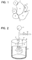
- the present invention provides a hydrogen absorbing alloy electrode which comprises at least two kinds of hydrogen absorbing alloys having different compositions and wherein particles A of a first hydrogen absorbing alloy having a CaCu 5 -type structure are joined to particles B of a second hydrogen absorbing alloy having a Zr-Ni Laves-phase structure to form at the resulting joint interfaces a joint layer C of a new composition containing the component elements of the first and second hydrogen absorbing alloys.
- the particles A of the first hydrogen absorbing alloy are joined to the particles B of the second hydrogen absorbing alloy by sintering or mechanical alloying, whereby the surfaces of particles A and B to be joined are heated, permitting the component elements of the first and second alloys to diffuse through the joints to form a joint layer C of new composition.
- the first hydrogen absorbing alloy has a CaCu 5 -type structure, which affords an increased degree of initial activation.
- the second hydrogen absorbing alloy has a Zr-Ni Laves-phase structure, which provides an increased discharge capacity.
- the joint layer C having a new composition different from those of the first and second hydrogen absorbing alloys exhibits the characteristics of the two alloys in synergism.
- the electrode in its entirety exhibits characteristics superior to the inherent characteristics of the first and second hydrogen absorbing alloys in respect of both initial activation degree and charge-discharge cycle life.
- the first hydrogen absorbing alloy has a double-phase CaCu 5 -type crystal structure
- the second hydrogen absorbing alloy has an AB 2 -type Laves-phase structure of single phase.
- the first hydrogen absorbing alloy has a double-phase crystal structure, a further improved degree of initial activation is available.
- the second hydrogen absorbing alloy has a single-phase crystal structure and is therefore superior in discharge capacity.
- the joint layer C accordingly has outstanding characteristics synergistically resulting from these characteristics.
- the first and second hydrogen absorbing alloys are substantially identical in equilibrium hydrogen pressure at the same temperature. This enables hydrogen to readily pass through the interface between the first hydrogen absorbing alloy and the second hydrogen absorbing alloy joined thereto, consequently further improving the initial activation degree and charge-discharge cycle life of the hydrogen absorbing alloy electrode.
- the hydrogen absorbing alloy which is the lower of the two hydrogen absorbing alloys in proportion is present in a proportion of at least 5 wt. %. This reliably forms the required joint layer C between the particles A of the first hydrogen absorbing alloy and the particles B of the second hydrogen absorbing alloy.
- the hydrogen absorbing alloy electrode embodying the invention has characteristics synergistically afforded by, and superior to, the inherent characteristics of the different component hydrogen absorbing alloys.
- the hydrogen absorbing alloys of AB 5 -type crystal structure have characteristics which vary with the composition thereof, the degree of initial activation is generally in trade-off relation with charge-discharge cycle life, such that the alloy which is excellent in one of these characteristics is inferior in the other. Accordingly, if an AB 5 -type alloy with a composition of superior initial activation degree and another AB 5 -type alloy with a composition of superior charge-discharge cycle life are mixed together and made into a hydrogen absorbing alloy electrode by molding and sintering, the electrode obtained possesses the characteristics of both alloys.
- the fact that the electrode is made of two kinds of AB 5 -type alloys having the same crystal structure renders hydrogen highly mobile in the electrode, realizing improvements in both the characteristics of initial activation degree and charge-discharge cycle life.
- the present invention provides another hydrogen absorbing alloy electrode wherein particles A of a first hydrogen absorbing alloy having a CaCu 5 -type structure are joined to particles B of a second hydrogen absorbing alloy having a CaCu 5 -type structure and different from the first hydrogen absorbing alloy in composition to form at the resulting joint interfaces a joint layer C of a new composition containing the component elements of the first and second hydrogen absorbing alloys.
- the particles A of the first hydrogen absorbing alloy are joined to the particles B of the second hydrogen absorbing alloy by sintering or mechanical alloying, whereby the surfaces of particles A and B to be joined are heated, permitting the component elements of the first and second alloys to diffuse through the joints to form a joint layer C of new composition.
- the first hydrogen absorbing alloy used has a composition of excellent degree of initial activation
- the second hydrogen absorbing alloy used has a composition of excellent charge-discharge cycle life, with the result that the joint layer C exhibits characteristics synergistically resulting from those of the two alloys.
- the electrode in its entirety exhibits characteristics superior to the inherent characteristics of the first and second hydrogen absorbing alloys in respect of both initial activation degree and charge-discharge cycle life.
- the first and second hydrogen absorbing alloys are the same in respect of the component elements. This enables hydrogen to readily pass through the joint interface between the first and second hydrogen absorbing alloys, consequently giving improved initial activation degree and charge-discharge cycle life to the electrode.
- the hydrogen absorbing alloy electrode embodying the invention has characteristics synergistically afforded by, and superior to, the inherent characteristics of the different component hydrogen absorbing alloys.
- the present invention provides another hydrogen absorbing alloy electrode which comprises at least two kinds of hydrogen absorbing alloys having different compositions and wherein particles A of a first hydrogen absorbing alloy having a Zr-Ni Laves-phase structure are joined to particles B of a second hydrogen absorbing alloy having a Zr-Ni Laves-phase structure and different from the first hydrogen absorbing alloy in composition to form at the resulting joint interfaces a joint layer C of a new composition containing the component elements of the first and second hydrogen absorbing alloys.
- the particles A of the first hydrogen absorbing alloy are joined to the particles B of the second hydrogen absorbing alloy by sintering or mechanical alloying, whereby the surfaces of particles A and B to be joined are heated, permitting the component elements of the first and second alloys to diffuse through the joints to form a joint layer C of new composition.
- the first hydrogen absorbing alloy used has a composition of excellent degree of initial activation
- the second hydrogen absorbing alloy used has a composition of excellent charge-discharge cycle life, with the result that the joint layer C exhibits characteristics synergistically resulting from those of the two alloys.
- the electrode in its entirety exhibits characteristics superior to the inherent characteristics of the first and second hydrogen absorbing alloys in respect of both initial activation degree and charge-discharge cycle life.
- the hydrogen absorbing alloy electrode embodying the invention has characteristics synergistically afforded by, and superior to, the inherent characteristics of the different component hydrogen absorbing alloys.
- a hydrogen absorbing alloy electrode embodying the invention comprises particles A of a first hydrogen absorbing alloy having a CaCu 5 -type structure, and particles B of a second hydrogen absorbing alloy joined to the particles A and having a Zr-Ni Laves-phase structure, with a joint layer C formed at the resulting joint interfaces and having a new composition containing the component elements of the first and second hydrogen absorbing alloys.
- first hydrogen absorbing alloys which are excellent in initial activation degree and charge-discharge cycle life for use in the first embodiment are MmNi 3.1 CoAl 0.2 Mn 0.7 (mother alloy A1) having a single-phase crystal structure, MmNi 3.1 CoAl 0.4 Mn 0.45 Ti 0.05 (mother alloy A2) having a double-phase crystal structure, and MmNi 3.1 Co 0.9 Al 0.45 Mn 0.5 Ti 0.05 (mother alloy A3) having a double-phase crystal structure.
- second hydrogen absorbing alloys having a great discharge capacity are ZrNi l.2 V 0.4 Mn 0.4 (mother alloy B1) having a double-phase crystal structure, and ZrNi l.1 V 0.2 Mn 0.7 (mother alloy B2) having a single-phase crystal structure.
- the hydrogen absorbing alloys At 40°C and at a hydrogen concentration of 0.5 (H/M), the hydrogen absorbing alloys have the following equilibrium hydrogen pressures: 0.52 atm for mother alloy Al, 0.41 atm for mother alloy A2, 0.22 atm for mother alloy A3, 0.25 atm for mother alloy B1, and 0.21 atm for mother alloy B2.
- Mm (misch metal) for use in the present embodiment is a mixture of rare-earth elements in the La:Ce:Pr:Nd ratio of 30:40:10:20 (by weight).
- Described below are a process for preparing the mother alloys, processes for preparing the electrodes, a method of determining the electrochemical characteristics and the results of determination.
- each of mother alloys A1 to A3, B1 and B2 were mixed together in a specified molar ratio, melted in an arc furnace having an argon atmosphere and then spontaneously cooled to prepare a block of hydrogen absorbing alloy.
- the alloy block was pulverized into a powder having a mean particle size of 120 ⁇ m.
- Hydrogen absorbing alloys were prepared from 50 g portions of the mother alloy powders by mixing the powder portions in the above-mentioned combinations, followed by sintering or mechanical alloying.
- each powder mixture was held heated in an inert gas at 1000°C for 8 hours, whereby the two mother alloy powders were joined to each other and made into a composite material.
- the powder mixture was placed into a rotor rotating at a high speed (13000 r.p.m.) and thereby repeatedly subjected to mechanical energy such as impact force or frictional force.
- the two mother alloy powders were joined to each other with the heat generated by the process and made into a composite material.
- the composition of each of the hydrogen absorbing alloys thus prepared was determined by EPMA analysis.
- Each alloy prepared by sintering or mechanical alloying was pulverized into a powder having a mean particle size of 75 ⁇ m, whereby the joint interfaces between the alloy particles having a CaCu 5 -type structure and the alloy particles having a Zr-Ni Laves-phase structure were exposed on the resulting surfaces.
- a hydrogen absorbing alloy electrode in the form of a disk with a diameter of 20 mm was prepared by mixing 0.1 g of polytetrafluoroethylene (PTFE) serving as a binder with 0.5 g of the alloy powder, filling a porous piece of blowing nickel (conductive substrate) with the mixture and press-molding the resulting piece at 1.2 tons/cm 2 .
- the electrode can be prepared alternatively by adding an aqueous solution containing a binder to the alloy powder to obtain a paste, and coating opposite surfaces of a nickel-plated piece of punching metal (conductive substrate) with the paste.
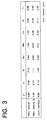
- each test cell comprises a closed polypropylene container 5 of insulating properties, and three electrodes arranged in the interior of the container 5, i.e., a test electrode 2 which is the hydrogen absorbing electrode to be tested, a sintered nickel electrode 3 in the form of a hollow cylinder and having a sufficiently greater electrochemical capacity than the test electrode 2, and a sintered nickel reference electrode 4 in the form of a plate.
- the sintered nickel electrode 3 is supported by the lower end of a positive-electrode lead 7 connected to the top wall 6 of the closed container 5.
- the test electrode 2 is accommodated in the nickel electrode 3 centrally thereof and vertically supported by the lower end of a negative-electrode lead 8 connected to the top wall 6 of the container 5.
- the leads 7 and 8 extend through the top wall 6 of the container 5 and are connected respectively to a positive-electrode terminal 9 and a negative-electrode terminal 10.
- the test electrode 2 and the nickel electrode 3 are immersed in an alkali electrolyte (30 wt. % aqueous solution of potassium hydroxide) placed in the container 5.
- the closed container 5 is filled with nitrogen gas in an upper space above the alkali electrolyte to subject the test electrode 2 to a predetermined pressure (7 atm).
- a relief pipe 13 Connected to the center of top wall 6 of the container 5 is a relief pipe 13 provided with a pressure gauge 11 and a relief valve 12 for preventing the internal pressure of the container 5 from building up above the predetermined value.
- each test cell was charged at room temperature and 50 mA/g for 8 hours, then held at rest for 1 hour, subsequently discharged at 50 mA/g to a final voltage of 0.9 V and thereafter held at rest for l hour. This charge-discharge cycle was repeated to measure the discharge capacity (mAh/g) every charge-discharge cycle.
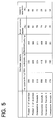
- FIG. 3 shows the result of EPMA analysis conducted for the hydrogen absorbing alloy electrode prepared by sintering from the foregoing combination of mother alloy A2 (MmNi 3.1 CoAl 0.4 Mn 0.45 Ti 0.05 ) and mother alloy B2 (ZrNi l.1 V 0.2 Mn 0.7 ).
- the components of mother alloy A2 are detected in the respective molar ratios as an alloy species 1, and the components of mother alloy B2 are detected in the listed molar ratios as an alloy species 2. Further a new composition different from the compositions of the alloy species 1, 2 is detected at joint interfaces between alloy particles. The same result as above was obtained with the hydrogen absorbing alloy electrode prepared by mechanical alloying.
- FIG. 4 shows the electrochemical characteristics of hydrogen absorbing alloy electrodes determined.
- These electrodes are an electrode (Product 1 of the invention) prepared from "alloy combination 1," i.e., the combination of mother alloy A1 (MmNi 3.1 CoAl 0.2 Mn 0.7 alloy of single phase) and mother alloy B1 (ZrNi l.2 V 0.4 Mn 0.4 alloy of double phase) by sintering, an electrode (Product 2 of the invention) prepared from the same "alloy combination l" by mechanical alloying, an electrode (Comparative Example 1) prepared from mother alloy A1 only, an electrode (Comparative Example 2) prepared from mother alloy B1 only, an electrode (Comparative Example 3) prepared from the powder mixture of mother alloy Al and mother alloy B1 by press molding only without sintering or mechanical alloying, and an electrode (Comparative Example 4) prepared from the powder mixture of mother alloy A1 and mother alloy B1 by press molding and subsequent sintering.
- alloy 1 the combination 1
- mother alloy B1 Zr
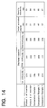
- the discharge capacity values listed are the value given by the first cycle which is governed by the initial activation degree, the value given by the 50th cycle which is governed by charge-discharge cycle life and the maximum capacity value obtained during the repeated charge-discharge cycles.
- the initial activation degree is expressed in terms of the ratio (%) of the discharge capacity of the first cycle to the maximum capacity.
- the initial activation degree can be quantitatively evaluated by this ratio.
- the capacity retentivity is expressed in terms of the ratio (%) of the discharge capacity of the 50th cycle to the maximum capacity.
- the charge-discharge cycle life can be quantitatively determined by this value.
- Comparative Example 3 With Comparative Example 3, the two kinds of mother alloys are merely mixed together, failing to form joint interfaces, and the initial activation degree and the capacity retentivity attained reflect nothing more than an effect of the combination of Comparative Examples 1 and 2. Comparative Example 4 fails to achieve a sufficient improvement since joint interfaces are not exposed. Products 1 and 2 of the invention are superior to Comparative Examples in initial activation degree and capacity retentivity. This substantiates that the exposed joint interfaces produce a synergistic effect on the initial activation degree and charge-discharge cycle life.
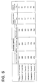
- FIG. 5 shows the electrochemical characteristics of hydrogen absorbing alloy electrodes determined.
- These electrodes are an electrode (Product 1 of the invention) prepared from "alloy combination 2," i.e., the combination of mother alloy A2 (MmNi 3.1 CoAl 0.4 Mn 0.45 Ti 0.05 alloy of double phase) and mother alloy B2 (ZrNi l.1 V 0.2 Mn 0.7 alloy of single phase) by sintering, an electrode (Product 2 of the invention) prepared from the same "alloy combination 2" by mechanical alloying, an electrode (Comparative Example 1) prepared from mother alloy A2 only, an electrode (Comparative Example 2) prepared from mother alloy B2 only, an electrode (Comparative Example 3) prepared from the powder mixture of mother alloy A2 and mother alloy B2 by press molding only without sintering or mechanical alloying, and an electrode (Comparative Example 4) prepared from the powder mixture of mother alloy A2 and mother alloy B2 by press molding and subsequent sintering.
- alloy 1 of the invention prepared from "allo
- Products 1 and 2 of the invention achieve a further improvement over "alloy combination 1" both in initial activation degree and in capacity retentivity.
- the improvement is attributable to the use of "alloy combination 2" wherein mother alloy A2 has a double phase and mother alloy B2 has a single phase. More specifically, the double-phase crystal structure of mother alloy A2 results in a higher initial activation degree and greater capacity retentivity than the single phase, while the single-phase crystal structure of mother alloy B2 gives a greater discharge capacity than the double phase.
- FIG. 6 shows the electrochemical characteristics of hydrogen absorbing alloy electrodes determined.
- These electrodes are an electrode (Product 1 of the invention) prepared from "alloy combination 3," i.e., the combination of mother alloy A3 (MmNi 3.1 Co 0.9 Al 0.45 Mn 0.5 Ti 0.05 alloy of double phase) and mother alloy B2 (ZrNi l.1 V 0.2 M 0.7 alloy of single phase) by sintering, an electrode (Product 2 of the invention) prepared from the same "alloy combination 3" by mechanical alloying, an electrode (Comparative Example 1) prepared from mother alloy A3 only, an electrode (Comparative Example 2) prepared from mother alloy B2 only, an electrode (Comparative Example 3) prepared from the powder mixture of mother alloy A3 and mother alloy B2 by press molding only without sintering or mechanical alloying, and an electrode (Comparative Example 4) prepared from the powder mixture of mother alloy A3 and mother alloy B2 by press molding and subsequent sintering.
- alloy 1 of the invention prepared from "allo
- Products 1 and 2 of the invention both achieve a higher initial activation degree and greater capacity retentivity than "alloy combination 2."
- the reason is that since mother alloy A3 and mother alloy B2 have approximately the same equilibrium hydrogen pressure at the same temperature in the case of "alloy combination 3," the interface between mother alloy A3 and mother alloy B2 permits hydrogen to readily pass therethrough, hence further improvements in initial activation degree and capacity retentivity.
- Hydrogen absorbing alloy electrodes were prepared by sintering from combinations of alloys equivalent to "alloy combination 3," i.e., from MmNi 3.0 Co 0.85 Al 0.6 Mn 0.5 Ti 0.05 alloy and ZrNi l.1 V 0.2 Mn 0.7 alloy as mixed together in varying ratios, and tested for maximum capacity, initial activation degree and capacity retentivity.
- FIG. 7 shows the results.
- the proportion of one of the alloys to be mixed together is preferably 20 to 80 wt. %, more preferably 40 to 60 wt. %, most preferably 50 wt. %.
- alkali dry batteries battery capacity: 1000 mAh
- the other components of the battery to be used include a known centered nickel electrode serving as the positive electrode, a separator of alkali-resistant nonwoven fabric and 30 wt. % aqueous solution of potassium hydroxide serving as the electrolyte.
- the alkali dry battery then obtained exhibits higher performance than conventionally.
- a hydrogen absorbing alloy electrode embodying the invention comprises particles A of a first hydrogen absorbing alloy having a CaCu 5 -type structure, and particles B of a second hydrogen absorbing alloy joined to the particles A, having a CaCu 5 -type structure and different from the first hydrogen absorbing alloy in composition, with a joint layer C formed at the resulting joint interfaces and having a new composition containing the component elements of the first and second hydrogen absorbing alloys.
- first hydrogen absorbing alloys which are excellent in initial activation degree are MmNi 3.1 Co 1.0 Mn 0.9 alloy (mother alloy A1), MmNi 3.3 Co 0.9 Al 0.1 Mn 0.7 alloy (mother alloy A2) and MmNi 3.1 Co 0.9 Al 0.3 Mn 0.7 alloy (mother alloy A3) which have an AB 5 -type crystal structure.
- MmNi 3.0 Co 1.0 Al 0.9 Mn 0.1 alloy (mother alloy B1) having an AB 5 -type crystal structure.
- the hydrogen absorbing alloys have the following equilibrium hydrogen pressures: 0.65 atm for mother alloy Al, 0.40 atm for mother alloy A2, 0.25 atm for mother alloy A3, and 0.25 atm for mother alloy B1.
- Mm (misch metal) for use in the present embodiment is a mixture of rare-earth elements in the La:Ce:Pr:Nd ratio of 30:40:10:20 (by weight).
- Described below are a process for preparing the mother alloys, process for preparing the electrodes, method of determining the electrochemical characteristics and the results of determination.
- each of mother alloys A1 to A3 and B1 was mixed together in a specified molar ratio, melted in an arc furnace having an argon atmosphere and then spontaneously cooled to prepare a block of hydrogen absorbing alloy.
- the alloy block was pulverized into a powder having a mean particle size of 120 ⁇ m.
- Composite alloys were prepared from 50 g portions of the mother alloy powders by mixing the powder portions in the above-mentioned combinations, followed by sintering or mechanical alloying.
- Each alloy prepared by sintering or mechanical alloying was pulverized again into a powder having a mean particle size of 75 ⁇ m.
- a hydrogen absorbing alloy electrode in the form of a disk with a diameter of 20 mm was thereafter prepared by mixing 0.1 g of polytetrafluoroethylene (PTFE) serving as a binder with 0.5 g of the alloy powder, filling a porous piece of blowing nickel with the mixture and press-molding the resulting piece at 1.2 tons/cm 2 .
- PTFE polytetrafluoroethylene
- single electrode test cells were assembled which were the same as the one used for the first embodiment and shown in FIG. 2.
- each test cell was subjected to repeated charge-discharge cycles to measure the discharge capacity (mAh/g) every cycle.
- FIG. 8 shows the result of EPMA analysis conducted for the hydrogen absorbing alloy electrode prepared by sintering from the foregoing combination of mother alloy A1 (MmNi 3.1 Co 1.0 Mn 0.9 ) and mother alloy B1 (MmNi 3.0 Co 1.0 Al 0.9 Mn 0.1 ).
- the components of mother alloy A1 are detected in the respective molar ratios as an alloy species 1, and the components of mother alloy B1 are detected in the listed molar ratios as an alloy species 2. Further a new composition different from the compositions of the alloy species 1, 2 is detected at joint interfaces between alloy particles. The same result as above was obtained with the hydrogen absorbing alloy electrode prepared by mechanical alloying.
- FIG. 9 shows the electrochemical characteristics of hydrogen absorbing alloy electrodes determined.
- These electrodes are an electrode (Product 1 of the invention) prepared from "alloy combination 1," i.e., the combination of mother alloy A1 (MmNi 3.1 Co 1.0 Mn 0.9 ) and mother alloy B1 (MmNi 3.0 Co 1.0 Al 0.9 Mn 0.1 ) by sintering, an electrode (Product 2 of the invention) prepared from the same "alloy combination l" by mechanical alloying, an electrode (Comparative Example 1) prepared from mother alloy A1 only, an electrode (Comparative Example 2) prepared from mother alloy B1 only, and an electrode (Comparative Example 3) prepared from the powder mixture of mother alloy Al and mother alloy B1 by press molding only without sintering or mechanical alloying.
- Products 1 and 2 of the invention are both improved over the three comparative examples in initial activation degree and capacity retentivity.
- Comparative Example 3 wherein the two alloys are merely mixed together, and no joint layer is formed substantiates that the joint layer of the invention produces a synergistic effect on the initial activation degree and charge-discharge cycle life.
- FIG. 10 shows the electrochemical characteristics of hydrogen absorbing alloy electrodes determined.
- These electrodes are an electrode (Product 1 of the invention) prepared from "alloy combination 2," i.e., the combination of mother alloy A2 (MmNi 3.3 Co 0.9 Al 0.1 Mn 0.7 ) and mother alloy B1 (MmNi 3.0 Co 1.0 Al 0.9 Mn 0.1 ) by sintering, an electrode (Product 2 of the invention) prepared from the same "alloy combination 2" by mechanical alloying, an electrode (Comparative Example 1) prepared from mother alloy A2 only, an electrode (Comparative Example 2) prepared from mother alloy B1 only, and an electrode (Comparative Example 3) prepared from the powder mixture of mother alloy A2 and mother alloy B1 by press molding only without sintering or mechanical alloying.
- Products 1 and 2 of the invention achieve an improvement over the foregoing "alloy combination 1" both in initial activation degree and capacity retentivity.
- the reason is that since mother alloy A2 and mother alloy B1 in "alloy combination 2" have nearly the same composition, hydrogen readily passes through the joint interface between these mother alloys, hence improved initial activation degree and capacity retentivity.
- FIG. 11 shows the electrochemical characteristics of hydrogen absorbing alloy electrodes determined.
- These electrodes are an electrode (Product 1 of the invention) prepared from "alloy combination 3," i.e., the combination of mother alloy A3 (MmNi 3.1 Co 0.9 Al 0.3 Mn 0.7 ) and mother alloy B1 (MmNi 3.0 Co 1.0 Al 0.9 Mn 0.1 ) by sintering, an electrode (Product 2 of the invention) prepared from the same "alloy combination 3" by mechanical alloying, an electrode (Comparative Example 1) prepared from mother alloy A3 only, an electrode (Comparative Example 2) prepared from mother alloy B1 only, and an electrode (Comparative Example 3) prepared from the powder mixture of mother alloy A3 and mother alloy B1 by press molding only without sintering or mechanical alloying.
- Products 1 and 2 of the invention both achieve a higher initial activation degree and greater capacity retentivity than "alloy combination 2.”
- mother alloy A3 and mother alloy B1 in "alloy combination 3" have approximately the same equilibrium hydrogen pressure at the same temperature, the joint interface between mother alloy A3 and mother alloy B1 permits hydrogen to readily pass therethrough, hence further improvements in initial activation degree and capacity retentivity.
- Hydrogen absorbing alloy electrodes were prepared by sintering from the same combination as "alloy combination 3," i.e., from mother alloy A3 and mother alloy B1 as mixed together in varying ratios, and tested for maximum capacity, initial activation degree and capacity retentivity.
- FIG. 12 shows the results.
- the proportion of one of the alloys to be mixed together is preferably 20 to 80 wt. %, more preferably 40 to 60 wt. %, most preferably 50 wt. %.
- alkali dry batteries battery capacity: 1000 mAh
- the other components of the battery to be used include a known sintered nickel electrode serving as the positive electrode, a separator of alkali-resistant nonwoven fabric and 30 wt. % aqueous solution of potassium hydroxide serving as the electrolyte.
- the alkali dry battery then obtained exhibits higher performance than conventionally.
- the hydrogen absorbing alloy electrode can be prepared alternatively by pulverizing different kinds of hydrogen absorbing alloys into powders and molding a mixture of the powders directly into an electrode by sintering.
- a hydrogen absorbing alloy electrode embodying the invention comprises particles A of a first hydrogen absorbing alloy having a Zr-Ni Laves-phase structure, and particles B of a second hydrogen absorbing alloy joined to the particles A, having a Zr-Ni Laves-phase structure and different from the first hydrogen absorbing alloy in composition, with a joint layer C formed at the resulting joint interfaces and having a new composition containing the component elements of the first and second hydrogen absorbing alloys.
- a first hydrogen absorbing alloy having a high initial activation degree i.e., ZrNi 1.1 Mn 0.7 V 0.2 alloy (mother alloy A1) having an AB 2 -type crystal structure
- second hydrogen absorbing alloys having an excellent charge-discharge cycle life i.e., ZrNi 1.1 Mn 0.5 V 0.2 Co 0.2 alloy (mother alloy B1), ZrNi 1.1 Mn 0.4 V 0.5 (mother alloy B2) and ZrNi 1.4 Mn 0.1 V 0.5 (mother alloy B3) which are of AB 2 -type crystal structure.
- the hydrogen absorbing alloys have the following equilibrium hydrogen pressure: 15.8 atm for mother alloy A1, 6.1 atm for mother alloy B1, 4.2 atm for mother alloy B2 and 16.3 atm for mother alloy B3.
- Described below are a process for preparing the mother alloys, process for preparing the electrodes, method of determining the electrochemical characteristics and the results of determination.
- each of mother alloys A1 and B1 to B3 were mixed together in a specified molar ratio, melted in an arc furnace having an argon atmosphere and then spontaneously cooled to prepare a block of hydrogen absorbing alloy.
- the alloy block was pulverized into a powder having a mean particle size of 120 ⁇ m.
- Composite alloys were prepared from 50 g portions of the mother alloy powders by mixing the powder portions in the above-mentioned combinations, followed by sintering or mechanical alloying.
- Each alloy prepared by sintering or mechanical alloying was pulverized again into a powder having a mean particle size of 75 ⁇ m.
- a hydrogen absorbing alloy electrode in the form of a disk with a diameter of 20 mm was thereafter prepared by mixing 0.1 g of polytetrafluoroethylene (PTFE) serving as a binder with 0.5 g of the alloy powder, filling a porous piece of blowing nickel with the mixture and press-molding the resulting piece at 1.2 tons/cm 2 .
- PTFE polytetrafluoroethylene
- single electrode test cells were assembled which were the same as the one used for the first embodiment and shown in FIG. 2.
- each test cell was subjected to repeated charge-discharge cycles to measure the discharge capacity (mAh/g) every cycle.
- FIG. 13 shows the result of EPMA analysis conducted for the hydrogen absorbing alloy electrode prepared by sintering from the foregoing combination of mother alloy A1 (ZrNi 1.1 Mn 0.7 V 0.2 ) and mother alloy B1 (ZrNi 1.1 Mn 0.5 V 0.2 Co 0.2 ).
- the components of mother alloy A1 are detected in the respective molar ratios as an alloy species 1, and the components of mother alloy B1 are detected in the listed molar ratios as an alloy species 2. Further a new composition different from the compositions of the alloy species 1, 2 is detected at joint interfaces between alloy particles. The same result as above was obtained with the hydrogen absorbing alloy electrode prepared by mechanical alloying.
- FIG. 14 shows the electrochemical characteristics of hydrogen absorbing alloy electrodes determined.
- These electrodes are an electrode (Product 1 of the invention) prepared from "alloy combination 1," i.e., the combination of mother alloy A1 (ZrNi 1.1 Mn 0.7 V 0.2 ) and mother alloy B1 (ZrNi 1.1 Mn 0.5 V 0.2 Co 0.2 ) by sintering, an electrode (Product 2 of the invention) prepared from the same "alloy combination l" by mechanical alloying, an electrode (Comparative Example 1) prepared from mother alloy A1 only, an electrode (Comparative Example 2) prepared from mother alloy B1 only, and an electrode (Comparative Example 3) prepared from the powder mixture of mother alloy Al and mother alloy B1 by press molding only without sintering or mechanical alloying.
- alloy 1 the combination 1
- mother alloy B1 ZrNi 1.1 Mn 0.5 V 0.2 Co 0.2
- FIG. 15 shows the electrochemical characteristics of hydrogen absorbing alloy electrodes determined.
- These electrodes are an electrode (Product 1 of the invention) prepared from "alloy combination 2," i.e., the combination of mother alloy A1 (ZrNi 1.1 Mn 0.7 V 0.2 ) and mother alloy B2 (ZrNi 1.1 Mn 0.4 V 0.5 ) by sintering, an electrode (Product 2 of the invention) prepared from the same "alloy combination 2" by mechanical alloying, an electrode (Comparative Example 1) prepared from mother alloy A1 only, an electrode (Comparative Example 2) prepared from mother alloy B2 only, and an electrode (Comparative Example 3) prepared from the powder mixture of mother alloy A1 and mother alloy B2 by press molding only without sintering or mechanical alloying.
- Products 1 and 2 of the invention exhibit a higher initial activation degree than is achieved by the foregoing "alloy combination 1" and are comparable to “alloy combination 1" in capacity retentivity.
- the reason is that since mother alloy A1 and mother alloy B2 in “alloy combination 2" have nearly the same composition, hydrogen readily passes through the joint interface between these mother alloys, hence improved initial activation degree and capacity retentivity.
- FIG. 16 shows the electrochemical characteristics of hydrogen absorbing alloy electrodes determined.
- These electrodes are an electrode (Product 1 of the invention) prepared from "alloy combination 3," i.e., the combination of mother alloy A1 (ZrNi 1.1 Mn 0.7 V 0.2 ) and mother alloy B3 (ZrNi 1.4 Mn 0.1 V 0.5 ) by sintering, an electrode (Product 2 of the invention) prepared from the same "alloy combination 3" by mechanical alloying, an electrode (Comparative Example 1) prepared from mother alloy A1 only, an electrode (Comparative Example 2) prepared from mother alloy B3 only, and an electrode (Comparative Example 3) prepared from the powder mixture of mother alloy A1 and mother alloy B3 by press molding only without sintering or mechanical alloying.
- Products 1 and 2 of the invention are both comparable to "alloy combination 2" in initial activation degree and superior to "alloy combination 2" in capacity retentivity.
- the reason is that since mother alloy A1 and mother alloy B3 in "alloy combination 3" have approximately the same equilibrium hydrogen pressure at the same temperature, the joint interface between mother alloy A1 and mother alloy B3 permits hydrogen to readily pass therethrough, hence further improvements in initial activation degree and capacity retentivity.
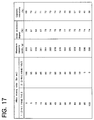
- Hydrogen absorbing alloy electrodes were prepared by sintering from the same combination as "alloy combination 3," i.e., from mother alloy A1 and mother alloy B3 as mixed together in varying ratios, and tested for maximum capacity, initial activation degree and capacity retentivity.
- FIG. 17 shows the results.
- the proportion of one of the alloys to be mixed together is preferably 20 to 80 wt. %, more preferably 40 to 60 wt. %, most preferably 50 wt. %.
- alkali dry batteries battery capacity: 1000 mAh
- the other components of the battery to be used include a known sintered nickel electrode serving as the positive electrode, a separator of alkali-resistant nonwoven fabric and 30 wt. % aqueous solution of potassium hydroxide serving as the electrolyte.
- the alkali dry battery then obtained exhibits higher performance than conventionally.
- first and second hydrogen absorbing alloys are usable as first and second hydrogen absorbing alloys insofar as they have a Zr-Ni Laves-phase structure.
Landscapes
- Chemical & Material Sciences (AREA)
- Chemical Kinetics & Catalysis (AREA)
- Electrochemistry (AREA)
- General Chemical & Material Sciences (AREA)
- Battery Electrode And Active Subsutance (AREA)
Applications Claiming Priority (9)
| Application Number | Priority Date | Filing Date | Title |
|---|---|---|---|
| JP34560495 | 1995-12-07 | ||
| JP34560395 | 1995-12-07 | ||
| JP345603/95 | 1995-12-07 | ||
| JP34560395A JP3369824B2 (ja) | 1995-12-07 | 1995-12-07 | 水素吸蔵合金電極 |
| JP34560495A JP3369825B2 (ja) | 1995-12-07 | 1995-12-07 | 水素吸蔵合金電極 |
| JP345604/95 | 1995-12-07 | ||
| JP34742295 | 1995-12-13 | ||
| JP34742295A JP3272226B2 (ja) | 1995-12-13 | 1995-12-13 | 水素吸蔵合金電極 |
| JP347422/95 | 1995-12-13 |
Publications (2)
| Publication Number | Publication Date |
|---|---|
| EP0777284A1 true EP0777284A1 (de) | 1997-06-04 |
| EP0777284B1 EP0777284B1 (de) | 2000-03-15 |
Family
ID=27341199
Family Applications (1)
| Application Number | Title | Priority Date | Filing Date |
|---|---|---|---|
| EP96119634A Expired - Lifetime EP0777284B1 (de) | 1995-12-07 | 1996-12-06 | Elektroden aus einer Wasserstoff-absorbierenden Legierung |
Country Status (5)
| Country | Link |
|---|---|
| US (1) | US5876869A (de) |
| EP (1) | EP0777284B1 (de) |
| KR (1) | KR100381490B1 (de) |
| CN (1) | CN1099139C (de) |
| DE (1) | DE69607111T2 (de) |
Cited By (1)
| Publication number | Priority date | Publication date | Assignee | Title |
|---|---|---|---|---|
| EP0961332A1 (de) * | 1998-05-19 | 1999-12-01 | Sanyo Electric Co., Ltd. | Elektrode aus wasserstoffspeichernder Legierung und Verfahren zu ihrer Herstellung |
Families Citing this family (1)
| Publication number | Priority date | Publication date | Assignee | Title |
|---|---|---|---|---|
| JP4587734B2 (ja) * | 2004-07-30 | 2010-11-24 | 三洋電機株式会社 | 水素吸蔵合金電極及び該電極を用いた二次電池 |
Citations (3)
| Publication number | Priority date | Publication date | Assignee | Title |
|---|---|---|---|---|
| JPH01129936A (ja) | 1987-11-13 | 1989-05-23 | Sanyo Electric Co Ltd | 水素吸蔵合金の製造方法 |
| JPH03173062A (ja) | 1989-12-01 | 1991-07-26 | Matsushita Electric Ind Co Ltd | 水素吸蔵電極とその製造法及びそれを用いた酸化金属―水素蓄電池 |
| JPH04162355A (ja) | 1990-10-25 | 1992-06-05 | Matsushita Electric Ind Co Ltd | 電池用水素吸蔵合金極 |
Family Cites Families (6)
| Publication number | Priority date | Publication date | Assignee | Title |
|---|---|---|---|---|
| JPS6429936A (en) * | 1987-07-27 | 1989-01-31 | Mitsubishi Electric Corp | Register re-mapping system |
| JPH03273062A (ja) * | 1990-03-22 | 1991-12-04 | Nippon Steel Chem Co Ltd | 熱可塑性樹脂組成物 |
| CN1029809C (zh) * | 1991-12-28 | 1995-09-20 | 南开大学 | 储氢合金电极 |
| JPH0668875A (ja) * | 1992-08-13 | 1994-03-11 | Matsushita Electric Ind Co Ltd | 電池用水素吸蔵合金極の製造法 |
| JP3265652B2 (ja) * | 1992-10-09 | 2002-03-11 | 松下電器産業株式会社 | アルカリ蓄電池およびその水素吸蔵合金の製造法 |
| KR100312699B1 (ko) * | 1994-12-28 | 2002-06-29 | 김순택 | 수소흡장합금및그제조방법 |
-
1996
- 1996-12-05 US US08/759,419 patent/US5876869A/en not_active Expired - Lifetime
- 1996-12-06 DE DE69607111T patent/DE69607111T2/de not_active Expired - Fee Related
- 1996-12-06 EP EP96119634A patent/EP0777284B1/de not_active Expired - Lifetime
- 1996-12-06 KR KR1019960062287A patent/KR100381490B1/ko not_active Expired - Fee Related
- 1996-12-07 CN CN96117400A patent/CN1099139C/zh not_active Expired - Fee Related
Patent Citations (3)
| Publication number | Priority date | Publication date | Assignee | Title |
|---|---|---|---|---|
| JPH01129936A (ja) | 1987-11-13 | 1989-05-23 | Sanyo Electric Co Ltd | 水素吸蔵合金の製造方法 |
| JPH03173062A (ja) | 1989-12-01 | 1991-07-26 | Matsushita Electric Ind Co Ltd | 水素吸蔵電極とその製造法及びそれを用いた酸化金属―水素蓄電池 |
| JPH04162355A (ja) | 1990-10-25 | 1992-06-05 | Matsushita Electric Ind Co Ltd | 電池用水素吸蔵合金極 |
Non-Patent Citations (2)
| Title |
|---|
| PATENT ABSTRACTS OF JAPAN vol. 013, no. 379 (C - 628) 22 August 1989 (1989-08-22) * |
| PATENT ABSTRACTS OF JAPAN vol. 016, no. 459 (E - 1268) 24 September 1992 (1992-09-24) * |
Cited By (2)
| Publication number | Priority date | Publication date | Assignee | Title |
|---|---|---|---|---|
| EP0961332A1 (de) * | 1998-05-19 | 1999-12-01 | Sanyo Electric Co., Ltd. | Elektrode aus wasserstoffspeichernder Legierung und Verfahren zu ihrer Herstellung |
| US6258482B1 (en) | 1998-05-19 | 2001-07-10 | Sanyo Electric Co., Ltd. | Hydrogen storage alloy electrode and method for fabrication thereof |
Also Published As
| Publication number | Publication date |
|---|---|
| KR100381490B1 (ko) | 2003-07-10 |
| US5876869A (en) | 1999-03-02 |
| DE69607111D1 (de) | 2000-04-20 |
| CN1099139C (zh) | 2003-01-15 |
| EP0777284B1 (de) | 2000-03-15 |
| DE69607111T2 (de) | 2000-09-28 |
| CN1157491A (zh) | 1997-08-20 |
| KR970054749A (ko) | 1997-07-31 |
Similar Documents
| Publication | Publication Date | Title |
|---|---|---|
| EP0450590A1 (de) | Wasserstoffspeichernde Elektrode und Verfahren zur Herstellung der Elektrode | |
| US6524746B2 (en) | Hydrogen absorbing alloy powder and process for producing same | |
| CA2101312C (en) | A paste type nickel electrode for an alkaline storage battery and an alkaline storage battery containing the electrode | |
| US5464654A (en) | Hydrogen-occlusion electrode and a method of manufacturing the electrode | |
| EP0506084B1 (de) | Wasserstoffspeicherlegierung und ihre Verwendung bei einer Elektrode | |
| JP2965475B2 (ja) | 水素吸蔵合金 | |
| US5876869A (en) | Hydrogen absorbing alloy electrodes | |
| US5242766A (en) | Hydrogen-occlusion electrode | |
| JP3598665B2 (ja) | 電池用活物質および電池 | |
| JP3272226B2 (ja) | 水素吸蔵合金電極 | |
| KR100398709B1 (ko) | 수소흡장합금전극및수소흡장합금전극의제조방법 | |
| JP3369824B2 (ja) | 水素吸蔵合金電極 | |
| US5401463A (en) | Hydrogen-occlusion alloy electrode | |
| JP3500031B2 (ja) | 水素吸蔵合金電極及びその作製方法 | |
| JPH0799055A (ja) | 水素二次電池 | |
| JP3369825B2 (ja) | 水素吸蔵合金電極 | |
| JPH04301045A (ja) | 水素吸蔵合金電極 | |
| JPH1012226A (ja) | 水素吸蔵合金電極及びその作製方法 | |
| JPH0690922B2 (ja) | 密閉型アルカリ蓄電池 | |
| EP0484964A1 (de) | Elektrode aus Wasserstoffeinlagerungslegierung | |
| JPH06168719A (ja) | ニッケル・水素電池用負極板、その製造法並びにニッケル・水素電池 | |
| JPS6243063A (ja) | アルカリ蓄電池 | |
| JPH09143503A (ja) | 水素吸蔵合金粉末及び製法 | |
| JPH07111885B2 (ja) | 金属酸化物−水素蓄電池とその製造方法 | |
| JPH0762475A (ja) | アルカリ蓄電池用の希土類系水素吸蔵合金 |
Legal Events
| Date | Code | Title | Description |
|---|---|---|---|
| PUAI | Public reference made under article 153(3) epc to a published international application that has entered the european phase |
Free format text: ORIGINAL CODE: 0009012 |
|
| AK | Designated contracting states |
Kind code of ref document: A1 Designated state(s): DE FR GB |
|
| 17P | Request for examination filed |
Effective date: 19971120 |
|
| 17Q | First examination report despatched |
Effective date: 19980218 |
|
| GRAG | Despatch of communication of intention to grant |
Free format text: ORIGINAL CODE: EPIDOS AGRA |
|
| GRAG | Despatch of communication of intention to grant |
Free format text: ORIGINAL CODE: EPIDOS AGRA |
|
| GRAH | Despatch of communication of intention to grant a patent |
Free format text: ORIGINAL CODE: EPIDOS IGRA |
|
| GRAH | Despatch of communication of intention to grant a patent |
Free format text: ORIGINAL CODE: EPIDOS IGRA |
|
| GRAA | (expected) grant |
Free format text: ORIGINAL CODE: 0009210 |
|
| AK | Designated contracting states |
Kind code of ref document: B1 Designated state(s): DE FR GB |
|
| REF | Corresponds to: |
Ref document number: 69607111 Country of ref document: DE Date of ref document: 20000420 |
|
| ET | Fr: translation filed | ||
| PLBE | No opposition filed within time limit |
Free format text: ORIGINAL CODE: 0009261 |
|
| STAA | Information on the status of an ep patent application or granted ep patent |
Free format text: STATUS: NO OPPOSITION FILED WITHIN TIME LIMIT |
|
| 26N | No opposition filed | ||
| REG | Reference to a national code |
Ref country code: GB Ref legal event code: IF02 |
|
| PGFP | Annual fee paid to national office [announced via postgrant information from national office to epo] |
Ref country code: GB Payment date: 20071205 Year of fee payment: 12 Ref country code: FR Payment date: 20071210 Year of fee payment: 12 |
|
| PGFP | Annual fee paid to national office [announced via postgrant information from national office to epo] |
Ref country code: DE Payment date: 20071129 Year of fee payment: 12 |
|
| GBPC | Gb: european patent ceased through non-payment of renewal fee |
Effective date: 20081206 |
|
| REG | Reference to a national code |
Ref country code: FR Ref legal event code: ST Effective date: 20090831 |
|
| PG25 | Lapsed in a contracting state [announced via postgrant information from national office to epo] |
Ref country code: DE Free format text: LAPSE BECAUSE OF NON-PAYMENT OF DUE FEES Effective date: 20090701 |
|
| PG25 | Lapsed in a contracting state [announced via postgrant information from national office to epo] |
Ref country code: GB Free format text: LAPSE BECAUSE OF NON-PAYMENT OF DUE FEES Effective date: 20081206 |
|
| PG25 | Lapsed in a contracting state [announced via postgrant information from national office to epo] |
Ref country code: FR Free format text: LAPSE BECAUSE OF NON-PAYMENT OF DUE FEES Effective date: 20081231 |