EP0777300A2 - Borne électrique femelle - Google Patents
Borne électrique femelle Download PDFInfo
- Publication number
- EP0777300A2 EP0777300A2 EP96118665A EP96118665A EP0777300A2 EP 0777300 A2 EP0777300 A2 EP 0777300A2 EP 96118665 A EP96118665 A EP 96118665A EP 96118665 A EP96118665 A EP 96118665A EP 0777300 A2 EP0777300 A2 EP 0777300A2
- Authority
- EP
- European Patent Office
- Prior art keywords
- side walls
- terminal
- bottom wall
- seam
- contact element
- Prior art date
- Legal status (The legal status is an assumption and is not a legal conclusion. Google has not performed a legal analysis and makes no representation as to the accuracy of the status listed.)
- Withdrawn
Links
- 238000004519 manufacturing process Methods 0.000 claims description 7
- 238000000034 method Methods 0.000 claims description 5
- 238000005452 bending Methods 0.000 claims 1
- 239000007769 metal material Substances 0.000 description 4
- 230000013011 mating Effects 0.000 description 2
- 238000003780 insertion Methods 0.000 description 1
- 230000037431 insertion Effects 0.000 description 1
- 239000007787 solid Substances 0.000 description 1
Images


Classifications
-
- H—ELECTRICITY
- H01—ELECTRIC ELEMENTS
- H01R—ELECTRICALLY-CONDUCTIVE CONNECTIONS; STRUCTURAL ASSOCIATIONS OF A PLURALITY OF MUTUALLY-INSULATED ELECTRICAL CONNECTING ELEMENTS; COUPLING DEVICES; CURRENT COLLECTORS
- H01R13/00—Details of coupling devices of the kinds covered by groups H01R12/70 or H01R24/00 - H01R33/00
- H01R13/02—Contact members
- H01R13/10—Sockets for co-operation with pins or blades
- H01R13/11—Resilient sockets
-
- H—ELECTRICITY
- H01—ELECTRIC ELEMENTS
- H01R—ELECTRICALLY-CONDUCTIVE CONNECTIONS; STRUCTURAL ASSOCIATIONS OF A PLURALITY OF MUTUALLY-INSULATED ELECTRICAL CONNECTING ELEMENTS; COUPLING DEVICES; CURRENT COLLECTORS
- H01R13/00—Details of coupling devices of the kinds covered by groups H01R12/70 or H01R24/00 - H01R33/00
- H01R13/02—Contact members
- H01R13/15—Pins, blades or sockets having separate spring member for producing or increasing contact pressure
- H01R13/187—Pins, blades or sockets having separate spring member for producing or increasing contact pressure with spring member in the socket
-
- H—ELECTRICITY
- H01—ELECTRIC ELEMENTS
- H01R—ELECTRICALLY-CONDUCTIVE CONNECTIONS; STRUCTURAL ASSOCIATIONS OF A PLURALITY OF MUTUALLY-INSULATED ELECTRICAL CONNECTING ELEMENTS; COUPLING DEVICES; CURRENT COLLECTORS
- H01R13/00—Details of coupling devices of the kinds covered by groups H01R12/70 or H01R24/00 - H01R33/00
- H01R13/02—Contact members
- H01R13/10—Sockets for co-operation with pins or blades
- H01R13/11—Resilient sockets
- H01R13/114—Resilient sockets co-operating with pins or blades having a square transverse section
Definitions
- This invention generally relates to the art of electrical connectors and, particularly, to a female terminal for use in an electrical connection.
- a typical electrical connector combination includes a plug connector and a receptacle connector, both of which mount or house interengageable electrical terminals.
- the plug connector is inserted into or mated with the receptacle connector to interengage the terminals.
- the terminals may take a variety of configurations, including male and female or pin and socket terminals.
- a known type of female socket terminal is elongated and has a terminating end and a contact end.
- the terminating end may be adapted for termination to an electrical wire, for instance.
- the contact end is box-shaped or generally rectangular in cross-section for receiving a male or pin contact or terminal.
- the female socket terminal typically is stamped and formed from sheet metal material, and spring sections may be stamped therefrom for resiliently gripping the pin contact or terminal.
- separate spring contact elements have been used with such female socket terminals.
- a female socket terminal employs a separate spring element to resiliently grip an inserted pin contact or terminal.
- the female socket terminal disclosed therein is generally rectangular in cross-section and includes a bottom plate portion having two sides.
- a pair of opposing side plate portions extend upwardly from both sides of the bottom plate portion.
- Two lug engagement holes are formed in the two side plate portions immediately adjacent the bottom plate portion.
- a pair of opposing top plate half portions extend inwardly from upper ends of the side plate portions.
- a spring element is mounted within the female terminal and includes a spring body and a pair of lug portions engaged within the lug engagement holes formed in the two side plates portions near the bottom plate portion.
- the top plate half portions and the side plate portions are spread apart to allow insertion of the spring element transverse to the longitudinal direction of the terminal until the lug portions of the spring element engage within the lug engagement holes formed in the two side plate portions near the bottom wall.
- the present invention is directed to solving the above problems and providing a box-type female socket terminal which is more reliable and easier to manufacture than the prior art.
- An object, therefore, of the invention is to provide a new and improved female electrical terminal of the character described.
- the female electrical terminal is elongated and includes a contact end and a terminating end.
- the contact end is generally rectangular in cross-section and is adapted to receive a male or pin contact.
- the contact end includes a bottom wall, and a pair of opposing side walls extending upwardly from opposite sides of the bottom wall.
- a lug-engaging hole is formed in each side wall near the top thereof.
- a pair of opposing top half walls extend inwardly from the tops of the side walls and define a seam therebetween.
- a spring contact element is located in the contact end, inside the seam and is adapted to bias the male contact into engagement with the bottom wall. The lug portions of the spring contact element engage in the lug-engaging holes.
- the male terminal is biased against the solid bottom wall of the contact end rather than upwardly against the top half walls and the open seam. Therefore, there is no tendency to spread the contact end apart.
- the spring contact element may be more easily assembled into the contact end longitudinally of the terminal rather than transversely thereof.
- the spring contact element includes a cantilevered contact blade which is sufficiently wide to engage substantial portions of the top half walls on opposite sides of the seam.
- a raised boss in the bottom wall, adapted for engaging the male terminal.
- the raised boss is provided by a raised rib extending longitudinally of the terminal. Such a raised rib could not be provided in the prior art because of the open seam against which the male terminal is biased.
- Female terminal 10 includes a terminating end, generally designated 12, and a contact end, generally designated 14.
- Terminating end 12 includes two pairs of crimp arms 16 and 18 for clamping onto an electrical wire.
- Contact end 14 is generally box-shaped or rectangular in cross-section and mounts a spring element, generally designated 20, for resiliently gripping a pin contact or male terminal inserted into the contact end in the direction of arrow "A".
- contact end 14 includes a bottom plate portion 22 and two side plate portions 24 extending upward from both sides of the bottom plate portion.
- Two lug engagement holes 26 are formed in both side plate portions 24 immediately above bottom plate portion 22.
- a pair of opposing top plate half portions 28 extend inwardly from upper ends of side plate portions 24 and are joined at an open seam 30 due to the fact that the terminal is stamped and formed of sheet metal material.
- Spring element 20 of prior art female terminal 10 includes a cantilevered and bowed spring body 32 projecting rearwardly in the terminal, and a pair of lug portions 34 engage within lug engagement holes 26 formed in the two side plate portions 24.
- spring body 32 of spring element 20 biases the male terminal upwardly against top plate half portions 28 which, in turn, problematically tends to open seam 30, particularly if the male terminal is cylindrical.
- Figure 2 shows the method of assembling prior art female terminal 10.
- side plate portions 24 and opposing top plate half portions 28 are spread apart, as shown, a sufficient distance for spring element 20 to be inserted in the direction of arrow "B".
- the spring element is inserted into contact end 14 perpendicular or transversely of the longitudinal direction of the terminal.
- the spring contact element is inserted downwardly until lugs 34 engage within lug engagement holes 26 at the bottom of side plate portions 24 near bottom wall 22, as shown in phantom in Figure 2.
- the side plate portions and the top plate half portions then are closed about the spring element to the closed configuration shown in Figure 1 and described above.
- an elongated female electrical terminal generally designated 40, is shown embodying the concepts of the present invention.
- the female terminal includes a contact end, generally designated 42, and a terminating end, generally designated 44.
- the contact end is generally box-shaped or rectangular in cross-section.
- the terminating end includes two pairs of crimp arms 46 for clamping onto an electrical wire.
- Contact end 42 of female terminal 40 includes a bottom wall 48 and a pair of opposing side walls 50 extending upwardly from opposite sides of the bottom wall.
- a lug-engaging opening or hole 52 is formed in each side wall 50 near the top thereof.
- a pair of opposing top half walls 54 extend inwardly form the tops of side walls 50 and define a seam 56 therebetween.
- An inwardly concave detent 58 is formed in top half walls 54 spanning seam 56. The detent 58 provides an anti-overstress means for the contact blade of the spring contact element described hereinafter.
- the entire elongated female electrical terminal 40, including contact end 42, is stamped and formed from conductive sheet metal material.
- a spring contact element generally designated 60, includes a cantilevered, inwardly bowed contact blade 62 terminating in a rounded distal end 64.
- a pair of lug portions 66 project transversely outwardly from the end of contact blade 62 opposite distal end 64.
- One of the lug portions 66 is shown projecting into one of the lug-engaging holes 52 in one of the side walls 50 in Figure 3.
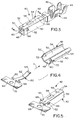
- Spring contact element 60 is shown in Figure 4 in a stage of manufacture wherein the spring contact element still is joined to a carrier strip 68 by a web portion 70. It readily can be seen that the spring contact element is stamped and formed from conductive sheet metal material, and a plurality of the spring contact elements are stamped and formed lengthwise along carrier strip 68 joined by web portions 70.
- side walls 50 and opposing top half walls 54 are spread apart, as shown, a sufficient distance for lug portions 66 of spring contact element 60 to be inserted in the direction of arrow "C".
- the side walls and top half walls need to be spread only a distance sufficient for the lug portions to pass between the junctures, as at 72, between the side walls and the top half walls.
- Figure 6 shows the location of spring contact element 60 within contact end 42 of the female terminal. It can be seen that contact blade 62 of the spring contact element is located at the top of the contact end with lug portions 66 captured within the lug-engaging holes 52 at the tops of side walls 50.
- Figure 6 also shows a feature of the invention wherein a portion of bottom wall 48 is formed with a raised boss in the form of a raised rib 80 extending longitudinally of the terminal.
- a portion of bottom wall 48 is formed with a raised boss in the form of a raised rib 80 extending longitudinally of the terminal.
- an inserted male terminal is sandwiched between the raised rib and cantilevered contact blade 62 of spring contact element 60.
- the raised rib portion of the bottom wall is effective to provide a more positive area of contact with the male terminal than simply the enlarged flat bottom wall 48 of the contact end.
- Such a positive engagement would not be possible with the prior art because the male terminal in the prior art is biased against the spreadable open seam of the contact end of the terminal.
- Figures 7 and 8 show a male terminal 82 inserted into contact end 42 and into engagement with cantilevered contact blade 62 of spring contact element 60. It can be seen that the contact blade has been compressed, whereby the contact blade essentially biases the male terminal downwardly in the direction of arrows "D" into positive engagement with raised rib 80 above bottom wall 48.
- Figure 8 also shows how lugs 66 are bent downwardly within recessed areas 84 in the outside of side walls 50 so that the lugs do not project outwardly beyond the confines of contact end 42 of the terminal.
- the downwardly bent lugs assist in preventing side walls 50 and top half walls 54 from spreading apart at seam 56.
- FIG. 8 shows that contact blade 62 of spring contact element 60 has a substantial width whereby the distal end 64 (Fig. 4) of the contact blade is engageable with substantial portions of top half walls 54 on opposite sides of open seam 56.
Landscapes
- Manufacturing Of Electrical Connectors (AREA)
- Coupling Device And Connection With Printed Circuit (AREA)
Applications Claiming Priority (2)
| Application Number | Priority Date | Filing Date | Title |
|---|---|---|---|
| US08/565,750 US5658174A (en) | 1995-12-01 | 1995-12-01 | Female electrical terminal |
| US565750 | 2000-05-08 |
Publications (2)
| Publication Number | Publication Date |
|---|---|
| EP0777300A2 true EP0777300A2 (fr) | 1997-06-04 |
| EP0777300A3 EP0777300A3 (fr) | 1998-02-04 |
Family
ID=24259940
Family Applications (1)
| Application Number | Title | Priority Date | Filing Date |
|---|---|---|---|
| EP96118665A Withdrawn EP0777300A3 (fr) | 1995-12-01 | 1996-11-21 | Borne électrique femelle |
Country Status (4)
| Country | Link |
|---|---|
| US (1) | US5658174A (fr) |
| EP (1) | EP0777300A3 (fr) |
| JP (1) | JP2934836B2 (fr) |
| KR (1) | KR100248968B1 (fr) |
Families Citing this family (24)
| Publication number | Priority date | Publication date | Assignee | Title |
|---|---|---|---|---|
| JP3159073B2 (ja) * | 1996-08-08 | 2001-04-23 | 住友電装株式会社 | 端子金具及びその製造方法 |
| JP3620014B2 (ja) | 1999-08-04 | 2005-02-16 | 矢崎総業株式会社 | 雌端子及びその製造方法 |
| US7595715B2 (en) * | 2007-09-27 | 2009-09-29 | Lear Corporation | High power case fuse |
| JP4982394B2 (ja) * | 2008-01-24 | 2012-07-25 | 矢崎総業株式会社 | 端子金具の電気接触部構造 |
| US8323061B2 (en) | 2009-01-20 | 2012-12-04 | Molex Incorporated | Miniature receptacle terminals |
| US8366497B2 (en) * | 2009-06-17 | 2013-02-05 | Lear Corporation | Power terminal |
| JP2011198567A (ja) * | 2010-03-18 | 2011-10-06 | Sumitomo Wiring Syst Ltd | 雌型端子金具 |
| US8951051B2 (en) | 2011-10-10 | 2015-02-10 | Lear Corporation | Connector having optimized tip |
| JP6124537B2 (ja) * | 2012-09-03 | 2017-05-10 | 矢崎総業株式会社 | メス端子 |
| US9166322B2 (en) | 2013-02-08 | 2015-10-20 | Lear Corporation | Female electric terminal with gap between terminal beams |
| US9548553B2 (en) | 2013-03-15 | 2017-01-17 | Lear Corporation | Terminal with front end protection |
| JP6044513B2 (ja) * | 2013-03-21 | 2016-12-14 | 住友電装株式会社 | 端子金具 |
| EP3005485B1 (fr) | 2013-06-07 | 2018-01-03 | FCI Asia Pte. Ltd. | Connecteur pour cable |
| DE102014011523B4 (de) | 2013-08-01 | 2025-06-26 | Lear Corporation | Elektrische anschlussanordnung |
| US9190756B2 (en) | 2013-08-01 | 2015-11-17 | Lear Corporation | Electrical terminal assembly |
| US9711926B2 (en) | 2013-11-19 | 2017-07-18 | Lear Corporation | Method of forming an interface for an electrical terminal |
| CN105934855B (zh) * | 2013-12-03 | 2020-01-17 | 富加宜(亚洲)私人有限公司 | 连接器和用于这种连接器的插针接收接触件 |
| JP6357334B2 (ja) * | 2014-03-28 | 2018-07-11 | 矢崎総業株式会社 | 圧着端子と電線の接続構造 |
| CN105140697B (zh) * | 2015-09-23 | 2025-04-25 | 连展科技(深圳)有限公司 | 插座电连接器 |
| DE102015122303B3 (de) * | 2015-12-15 | 2017-04-20 | Amphenol-Tuchel Electronics Gmbh | Steckverbinderbuchse |
| JP6543284B2 (ja) * | 2017-02-10 | 2019-07-10 | タイコエレクトロニクスジャパン合同会社 | 雌型コンタクト、及び、コンタクトの嵌合構造 |
| JP6544412B2 (ja) * | 2017-11-22 | 2019-07-17 | オムロン株式会社 | コネクタ用端子およびコネクタ |
| WO2019178520A1 (fr) | 2018-03-16 | 2019-09-19 | Fci Usa Llc | Connecteurs électriques à haute densité |
| JP7524704B2 (ja) * | 2020-10-09 | 2024-07-30 | I-Pex株式会社 | 端子 |
Citations (1)
| Publication number | Priority date | Publication date | Assignee | Title |
|---|---|---|---|---|
| US5441428A (en) | 1993-09-28 | 1995-08-15 | Yazaki Corporation | Female terminal parts |
Family Cites Families (10)
| Publication number | Priority date | Publication date | Assignee | Title |
|---|---|---|---|---|
| FR2198681A5 (fr) * | 1972-08-30 | 1974-03-29 | Amp Inc | |
| US5271741A (en) * | 1990-02-21 | 1993-12-21 | Yazaki Corporation | Female socket contact |
| JPH0494275U (fr) * | 1991-01-11 | 1992-08-17 | ||
| JP2904367B2 (ja) * | 1991-06-17 | 1999-06-14 | 矢崎総業株式会社 | 雌端子 |
| US5217382A (en) * | 1992-06-05 | 1993-06-08 | Interlock Corporation | Electric receptacle with shape memory spring member |
| JP2546255Y2 (ja) * | 1992-07-08 | 1997-08-27 | 矢崎総業株式会社 | 雌型端子金具 |
| JP2570469Y2 (ja) * | 1992-08-18 | 1998-05-06 | 日本エー・エム・ピー株式会社 | 雌型電気端子 |
| JP3285101B2 (ja) * | 1993-01-21 | 2002-05-27 | 矢崎総業株式会社 | 雌型端子 |
| JPH0750178A (ja) * | 1993-08-03 | 1995-02-21 | Yazaki Corp | 電気接続子とその製造方法 |
| US5427552A (en) * | 1993-11-22 | 1995-06-27 | Chrysler Corporation | Electrical terminal and method of fabricating same |
-
1995
- 1995-12-01 US US08/565,750 patent/US5658174A/en not_active Expired - Lifetime
-
1996
- 1996-11-21 EP EP96118665A patent/EP0777300A3/fr not_active Withdrawn
- 1996-11-22 JP JP8327774A patent/JP2934836B2/ja not_active Expired - Fee Related
- 1996-11-30 KR KR1019960060536A patent/KR100248968B1/ko not_active Expired - Fee Related
Patent Citations (1)
| Publication number | Priority date | Publication date | Assignee | Title |
|---|---|---|---|---|
| US5441428A (en) | 1993-09-28 | 1995-08-15 | Yazaki Corporation | Female terminal parts |
Also Published As
| Publication number | Publication date |
|---|---|
| JPH09180795A (ja) | 1997-07-11 |
| KR100248968B1 (ko) | 2000-03-15 |
| US5658174A (en) | 1997-08-19 |
| EP0777300A3 (fr) | 1998-02-04 |
| JP2934836B2 (ja) | 1999-08-16 |
| KR970054919A (ko) | 1997-07-31 |
Similar Documents
| Publication | Publication Date | Title |
|---|---|---|
| US5658174A (en) | Female electrical terminal | |
| EP0877390B1 (fr) | Borne électrique femelle | |
| EP0784356B1 (fr) | Borne électrique femelle | |
| US5207603A (en) | Dual thickness blade type electrical terminal | |
| US5647754A (en) | Short-circuit connector | |
| US20060014442A1 (en) | High current automotive electrical connector and terminal | |
| EP0795930B1 (fr) | Contact électrique recevant une broche avec une force de contact élevée | |
| AU611057B2 (en) | Electrical connector | |
| KR20050061590A (ko) | 가요성 리본 케이블용 클램프 커넥터 | |
| JP3620014B2 (ja) | 雌端子及びその製造方法 | |
| EP0644618A2 (fr) | Connecteur électrique avec moyens de verrouillage des contacts | |
| US4243286A (en) | Insulation displacement connector | |
| EP1089387A2 (fr) | Borne électrique femelle modulaire | |
| EP1935063A2 (fr) | Borne electrique multi-piece a receptacle | |
| EP1089388A2 (fr) | Borne électrique femelle modulaire | |
| JPH06260238A (ja) | 接続端子 | |
| EP0954059A1 (fr) | Connecteur électrique | |
| US4491379A (en) | Insulation displacement connector | |
| JP7287771B2 (ja) | コネクタ、及び、カバー | |
| JP2537455B2 (ja) | 接続端子 | |
| JP2002367739A (ja) | スイッチ機能付きコネクタ | |
| JPH10302860A (ja) | 同軸ケーブル接続具 | |
| EP1180824A2 (fr) | Fiche pour un dispositif de connexion | |
| JPH0494070A (ja) | 低挿入力コネクタ | |
| JPH0590818U (ja) | ジョイントコネクタ |
Legal Events
| Date | Code | Title | Description |
|---|---|---|---|
| PUAI | Public reference made under article 153(3) epc to a published international application that has entered the european phase |
Free format text: ORIGINAL CODE: 0009012 |
|
| AK | Designated contracting states |
Kind code of ref document: A2 Designated state(s): DE FR GB IT |
|
| PUAL | Search report despatched |
Free format text: ORIGINAL CODE: 0009013 |
|
| AK | Designated contracting states |
Kind code of ref document: A3 Designated state(s): DE FR GB IT |
|
| 17P | Request for examination filed |
Effective date: 19980720 |
|
| 17Q | First examination report despatched |
Effective date: 20000201 |
|
| STAA | Information on the status of an ep patent application or granted ep patent |
Free format text: STATUS: THE APPLICATION IS DEEMED TO BE WITHDRAWN |
|
| 18D | Application deemed to be withdrawn |
Effective date: 20000814 |