EP0777407B1 - Verfahren zur Abdichtung eines Gehäuses für elektromagnetische Bauteile und so abgedichtetes Gehäuse - Google Patents
Verfahren zur Abdichtung eines Gehäuses für elektromagnetische Bauteile und so abgedichtetes Gehäuse Download PDFInfo
- Publication number
- EP0777407B1 EP0777407B1 EP96118923A EP96118923A EP0777407B1 EP 0777407 B1 EP0777407 B1 EP 0777407B1 EP 96118923 A EP96118923 A EP 96118923A EP 96118923 A EP96118923 A EP 96118923A EP 0777407 B1 EP0777407 B1 EP 0777407B1
- Authority
- EP
- European Patent Office
- Prior art keywords
- shells
- container
- resin
- grooved
- outside
- Prior art date
- Legal status (The legal status is an assumption and is not a legal conclusion. Google has not performed a legal analysis and makes no representation as to the accuracy of the status listed.)
- Expired - Lifetime
Links
- 238000000034 method Methods 0.000 title claims description 26
- 238000007789 sealing Methods 0.000 title claims description 20
- 239000011324 bead Substances 0.000 claims description 19
- 229920005989 resin Polymers 0.000 claims description 19
- 239000011347 resin Substances 0.000 claims description 19
- 238000005304 joining Methods 0.000 claims description 12
- 239000002952 polymeric resin Substances 0.000 claims description 9
- 229920003002 synthetic resin Polymers 0.000 claims description 9
- 238000002347 injection Methods 0.000 claims description 6
- 239000007924 injection Substances 0.000 claims description 6
- 230000002427 irreversible effect Effects 0.000 claims description 4
- 230000000295 complement effect Effects 0.000 claims description 3
- 238000006116 polymerization reaction Methods 0.000 claims description 3
- 239000003795 chemical substances by application Substances 0.000 description 3
- 239000007788 liquid Substances 0.000 description 3
- 238000004026 adhesive bonding Methods 0.000 description 2
- 238000001764 infiltration Methods 0.000 description 2
- 230000008595 infiltration Effects 0.000 description 2
- 239000000463 material Substances 0.000 description 2
- 238000012544 monitoring process Methods 0.000 description 2
- 238000003466 welding Methods 0.000 description 2
- 239000004952 Polyamide Substances 0.000 description 1
- 239000004743 Polypropylene Substances 0.000 description 1
- 230000004888 barrier function Effects 0.000 description 1
- 230000001276 controlling effect Effects 0.000 description 1
- 238000000151 deposition Methods 0.000 description 1
- 230000008021 deposition Effects 0.000 description 1
- 229920001971 elastomer Polymers 0.000 description 1
- 239000000806 elastomer Substances 0.000 description 1
- 239000002245 particle Substances 0.000 description 1
- 229920002647 polyamide Polymers 0.000 description 1
- -1 polypropylene Polymers 0.000 description 1
- 229920001155 polypropylene Polymers 0.000 description 1
- 230000001105 regulatory effect Effects 0.000 description 1
- 238000004826 seaming Methods 0.000 description 1
- 239000007787 solid Substances 0.000 description 1
- 239000000243 solution Substances 0.000 description 1
- 238000002604 ultrasonography Methods 0.000 description 1
Images
Classifications
-
- H—ELECTRICITY
- H05—ELECTRIC TECHNIQUES NOT OTHERWISE PROVIDED FOR
- H05K—PRINTED CIRCUITS; CASINGS OR CONSTRUCTIONAL DETAILS OF ELECTRIC APPARATUS; MANUFACTURE OF ASSEMBLAGES OF ELECTRICAL COMPONENTS
- H05K5/00—Casings, cabinets or drawers for electric apparatus
- H05K5/06—Hermetically-sealed casings
- H05K5/062—Hermetically-sealed casings sealed by a material injected between a non-removable cover and a body, e.g. hardening in situ
-
- H—ELECTRICITY
- H05—ELECTRIC TECHNIQUES NOT OTHERWISE PROVIDED FOR
- H05K—PRINTED CIRCUITS; CASINGS OR CONSTRUCTIONAL DETAILS OF ELECTRIC APPARATUS; MANUFACTURE OF ASSEMBLAGES OF ELECTRICAL COMPONENTS
- H05K5/00—Casings, cabinets or drawers for electric apparatus
- H05K5/06—Hermetically-sealed casings
- H05K5/063—Hermetically-sealed casings sealed by a labyrinth structure provided at the joining parts
Definitions
- the present invention relates to a method of assembling two elements obtaining a container of electromechanical components hermetically sealed and suitable to support loads able to separate the two elements forming the container itself, and to the sealed container thus obtained, and more particularly relates to a method for joining together in a leaktight and irreversible manner, two polymeric resin half-shells intended to enclose and protect the electromechanical components from external contaminating liquids and agents, using as adhesive bonding component an elastomeric resin which is chemically compatible with the resin of the half-shells and is able to form a continuous sealing bead, adhering intimately to both half-shells.
- the object of the present invention is to propose a method of hermetically sealing two half-shells forming a leaktight container for electromechanical components assuring simultaneously the structural continuity between the parties, and which overcomes the drawbacks exhibited by the methods currently in use in the art.
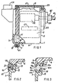
- 1 indicates a container with leaktight closure able to accommodate electromechanical components indicated for simplicity as a block 2, which by their nature require an environment which is perfectly sheltered from contaminating agents, whether liquid or solid.
- electromechanical components can, according to one non-limiting example, be electric motors, electronic circuits for controlling motors, control and regulating components, such as for example potentiometers and/or relays, etc.
- the container 1 is intended to accommodate an electromechanical device for monitoring and correcting the trim of the headlights of an automobile, comprising at least one electronic circuit CT for monitoring an electric motor ME, able to vary the trim of the headlights in a known manner, via the axial movement of a rod AT, moved by the motor ME and exiting from a wall of the container through a sealing bush BT; a connector CN able to receive the electrical connections necessary for the operation of the contained components can be associated integrally with the container.
- an electromechanical device for monitoring and correcting the trim of the headlights of an automobile comprising at least one electronic circuit CT for monitoring an electric motor ME, able to vary the trim of the headlights in a known manner, via the axial movement of a rod AT, moved by the motor ME and exiting from a wall of the container through a sealing bush BT; a connector CN able to receive the electrical connections necessary for the operation of the contained components can be associated integrally with the container.
- the container 1 consists substantially of two half-shells 3 and 4, made from a polymeric resin, for example polypropylene or polyamide.
- the two half-shells 3 and 4 can be specularly identical, consisting of an end wall 5 and four side walls 6, which terminate in an edge 7 of increased thickness with respect to that of the side walls 6; as a non-limiting alternative, as illustrated in Figure 1, one of the half-shells, for example the half-shell 3, can have the form of a cover (Fig. 1) provided with its own edge 8 of increased thickness, similar to the edge 7 of the other half-shell, and of complementary form, such as to be superimposable and to mate exactly.
- edges 7, 8 of the half-shells are machined such that they each exhibit an open grooved annular seat 9 and 10 respectively; the two grooved seats 9, 10 extend continuously along the whole run of the edges 7 and 8 and are arranged mutually facing one another in a substantially middle position with respect to the transverse dimension of each edge, such that, when the two half-shells 3 and 4 are joined, they form a single closed grooved seat 11 common to and included within the edges 7 and 8 of the said half-shells.
- the grooved seats 9 and 10 are delimited by two pairs of lateral walls (Fig. 3); 9a, 9b indicate the side walls on the inward side with respect to the grooved seats; 10a and 10b respectively indicate those arranged outside; the pairs of side walls 9a, 9b and 10a, 10b terminate in pairs of strip-like plane, inside front surfaces 12a, 12b and outside front surfaces 14a, 14b respectively, which extend throughout their run, and are able to be placed facing in pairs when the two half-shells 3 and 4 are joined.
- the overhang of the two inside front surfaces 12a and 12b is dimensioned such that the half-shells 3 and 4 abut only thereon, when the shells are joined.
- the plane outside front surfaces 14a and 14b, outside the seats 9,10, are made with a smaller overhang than that of the counterpart inside surfaces, so that, with the half-shells joined, the abovementioned plane surfaces 14a and 14b are spaced somewhat apart so as to create a channel consisting of a continuous crevice 16 extending along the joining region 17 of the half-shells and communicating on the one hand with the outside environment and on the other hand with the closed grooved seat 11.
- One of the two edges for example the edge 8, is provided with a rib 19 in relief, arranged adjacent to the inside front surface 12b and extending continuously over the whole run of the edge 8; similarly on the edge 7 of the other half-shell 4 there is made a groove 20 adjacent to the surface 12a and able to accommodate the rib 19, when the half-shells are joined, so as to create a positioning reference and a barrier against possible infiltrations of extraneous matter into the coupled half-shells.
- the method according to the present invention for hermetically and structurally sealing together the two half-shells 3 and 4 proceeds as follows.
- the half-shells 3 and 4 are joined, inserting the rib 19 into the corresponding groove 20, so that the surfaces 12a and 12b abut; the container thus closed is inserted into an injection mould, not shown, and then an elastomeric resin, chemically alike the resin of the container 1, is injected into the mould; the injected resin penetrates through the crevice 16 into the closed grooved seat 11 in order to form a sealing bead 18 of resin, which during the subsequent phase of hardening, by polymerization and/or curing, creates stable molecular bonds between the polymeric resin of the container 1 and the elastomeric resin of the bead 18.
- the container 1 becomes hermetically sealed and the components contained therein remain protected from any outside contaminating agent and, simultaneously, an irreversible (save for the breaking of the components) stable mechanical connection is produced between the half-shells, comparable to adhesive bonding.
- the mould can be shaped, for example, in such a way as to deposit a strip 21 of elastomeric resin of between 0.5 and 1 mm in thickness on the outside surface 22 of the container 1, arranged simmetrically along the joining region 17 of the half-shells, and united with continuity of the material with the forming sealing bead 18 contained in the crevice 16.
- elastomeric resin may be carried out on other regions of the outside surface 22 of the container 1, in order to form layers or beads of resin acting as sealing beads and non-rigid supports, for example in order to create a sealing ring 23 around an exit collar 24 of the rod AT of the motor ME; such a collar 24, by virtue of the strip 21, can be obtained through a single injection operation together with the sealing bead 18.
Landscapes
- Engineering & Computer Science (AREA)
- Microelectronics & Electronic Packaging (AREA)
- Gasket Seals (AREA)
- Casings For Electric Apparatus (AREA)
Claims (6)
- Verfahren für die Herstellung eines hermetisch abgedichteten Behälters (1), der zwei Polymerharz-Halbschalen (3, 4) umfaßt, wovon jede durch eine entsprechende Kante (7; 8) begrenzt ist, die die strukturelle Kontinuität zwischen den Halbschalen (3, 4) sicherstellt, wobei das Verfahren die folgenden Schritte umfaßt(a) Erzeugen komplementärer offener Nutsitze (9, 10) in einander zugewandten Stirnflächen (12a, 14a; 12b, 14b) der entsprechenden Kanten (7; 8) der ersten und der zweiten Halbschale (3, 4), wobei die Sitze (9, 10) mit wenigstens einem Kanal versehen sind, die mit der äußeren Umgebung in Verbindung steht;(b) Vereinigen der Halbschafen (3, 4), wobei dle offenen Nutsitze (9, 10) einander zugewandt angeordnet sind, um einen einzigen geschlossenen Nutsitz (11) zu bilden, der beiden vereinigten Kanten (7, 8) der Halbschalen (3, 4) gemeinsam ist und mit der äußeren Umgebung durch den wenigstens einen Kanal in Verbindung steht;(c) Einspritzen eines Elastomerharzes, das stabile molekulare Bindungen mit dem Polymerharz der Halbschalen (3, 4) erzeugen kann, in den geschlossenen Nutsitz (11);(d) Härtenlassen des eingespritzten Harzes durch Polymerisation und/oder Aushärten während einer Dauer, die ausreicht, um in dem geschlossenen Nutsitz (11) einen Dichtungswulst (18) zu bilden;
dadurch gekennzeichnet, daß(i) - der wenigstens eine Kanal aus einem ununterbrochenen Spalt (16) besteht, der sich längs eines gesamten Verbindungsbereichs (17) der Halbschalen (3, 4) erstreckt und zwischen dem geschlossenen Nutsitz (11) und der äußeren Umgebung angeordnet ist;(ii) - das Verfahren ferner die folgenden Schritte umfaßt:(e) Einsetzen der vereinigten Halbschalen (3, 4) in eine Druckgußform;(iii) - der Einspritzschritt (c) in der Druckgußform und durch den Spalt (16) ausgeführt wird, so daß der Dichtungswulst (18) gleichzeitig die Halbschalen (3, 4) leckdicht abdichtet und sie mittels der stabilen molekularen Bindungen zwischen dem den Wulst (18) bildenden Elastomerharz und dem Polymerharz der Halbschalen (3, 4) strukturell miteinander in unumkehrbarer Weise verbindet, um den Behälter (1) zu bilden. - Verfahren nach Anspruch 1, bei dem die Halbschalen (3, 4) elektromechanische Komponenten (2) für Kraftfahrzeuge aufnehmen können.
- Verfahren nach Anspruch 1 oder 2, dadurch gekennzeichnet, daß der Schritt (c) den Vorgang des Einspritzens des Elastomerharzes gleichzeitig wenigstens über einen Teil der äußeren Oberfläche (22) wenigstens einer der Halbschalen (3, 4) umfaßt, um einen Streifen (21) mit vorgegebener Dicke zu bilden, der an dem Dichtungswulst (18) sicher verankert ist.
- Verfahren nach Anspruch 3, dadurch gekennzeichnet, daß die äußere Oberfläche (22) längs des Verbindungsbereichs (17) der Halbschalen (3, 4) symmetrisch angeordnet ist.
- Verfahren nach einem der vorhergehenden Ansprüche, dadurch gekennzeichnet, daß die offenen Nutsitze (9; 10) durch zwei Paare von Seitenwänden (9a, 9b; 10a, 10b) begrenzt sind, wobei die Wände eines ersten Paars (9a, 9b), die sich in bezug auf den Nutsitz innen befinden, so bemessen sind, daß sie im Schritt (b) in einen gegenseitigen stirnseitigen Kontakt gelangen, um jeweilige Stirnflächen (12a; 12b) der Halbschalen (3; 4) in gegenseitigen Anschlag zu bringen; wobei die Wände eines zweiten Paars (10a, 10b), die sich außerhalb des offenen Nutsitzes (9, 10) befinden, stimseitig voneinander beabstandet sind, um den Spalt (16) zu bilden.
- Hermetisch dichter Behälter (1), insbesondere für die Unterbringung hermetischer elektromechanischer Komponenten (2) für Kraftfahrzeuge, der gemäß dem Verfahren nach einem der vorhergehenden Ansprüche erhalten wird und umfaßt: zwei Polymerharz-Halbschalen (3, 4), wovon jede durch eine entsprechende Kante (7; 8) begrenzt ist, die die strukturelle Kontinuität zwischen den Halbschalen (3, 4) sicherstellt; komplementäre offene Nutsitze (9, 10), die auf einander zugewandten Stirnflächen (12a, 14a; 12b, 14b) der entsprechenden Kanten (7; 8) der ersten und der zweiten Halbschale (3, 4) erzeugt worden sind, wobei die Sitze (9, 10) mit wenigstens einem Kanal versehen sind, der eine Verbindung mit der äußeren Umgebung herstellt, und die Kanten (7, 8) mit den offenen Nutsitzen (9, 10), die einander zugewandt sind, vereinigt sind, um einen einzigen geschlossenen Nutsitz (11) zu bilden, der beiden vereinigten Kanten (7, 8) der Halbschalen (3, 4) gemeinsam ist und mit der äußeren Umgebung durch den wenigstens einen Kanal in Verbindung steht; wobei in dem geschlossenen Nutsitz (11) ein Dichtungswulst (18) vorgesehen ist;
dadurch gekennzeichnet, daß(i) - der wenigstens eine Kanal aus einem ununterbrochenen Spalt (16) besteht, der sich längs des gesamten Verbindungsbereichs (17) der Halbschalen (3, 4) erstreckt und zwischen dem geschlossenen Nutsitz (11) und der äußeren Umgebung angeordnet ist;(ii) - der Dichtungswulst (18) erhalten wird durch Einspritzen eines Elastomerharzes, das mit dem Polymerharz der Halbschalen (3, 4) stabile molekulare Bindungen erzeugen kann, in den geschlossenen Nutsitz (11) und durch den Spalt (16) sowie durch Härtenlassen des eingespritzten Harzes durch Polymerisation und/oder Aushärten in einer Gießform;(iii) - der Dichtungswulst (18) die Halbschalen (3, 4) leckdicht abdichtet und gleichzeitig die Halbschalen (3, 4) mittels der stabilen molekularen Bindungen zwischen dem den Wulst (18) bildenden Elastomerharz und dem Polymerharz der Halbschalen (3, 4) strukturell verbindet, um den Behälter (1) zu bilden.
Applications Claiming Priority (2)
| Application Number | Priority Date | Filing Date | Title |
|---|---|---|---|
| ITTO950950 | 1995-11-28 | ||
| IT95TO000950A IT1280489B1 (it) | 1995-11-28 | 1995-11-28 | Metodo per sigillare ermeticamente un contenitore di componenti elettromeccanici e contenitore sigillato cosi' ottenuto. |
Publications (2)
| Publication Number | Publication Date |
|---|---|
| EP0777407A1 EP0777407A1 (de) | 1997-06-04 |
| EP0777407B1 true EP0777407B1 (de) | 2003-04-09 |
Family
ID=11413983
Family Applications (1)
| Application Number | Title | Priority Date | Filing Date |
|---|---|---|---|
| EP96118923A Expired - Lifetime EP0777407B1 (de) | 1995-11-28 | 1996-11-26 | Verfahren zur Abdichtung eines Gehäuses für elektromagnetische Bauteile und so abgedichtetes Gehäuse |
Country Status (3)
| Country | Link |
|---|---|
| EP (1) | EP0777407B1 (de) |
| DE (1) | DE69627274T2 (de) |
| IT (1) | IT1280489B1 (de) |
Cited By (2)
| Publication number | Priority date | Publication date | Assignee | Title |
|---|---|---|---|---|
| EP4474229A1 (de) * | 2023-06-09 | 2024-12-11 | LINEA 3 S.r.l. | Behälter für eine flüssigkeitsmischung zur versorgung der scheibenwischer eines kraftfahrzeugs und verfahren zur herstellung eines solchen behälters |
| EP4431342A4 (de) * | 2021-11-11 | 2025-11-12 | Valeo Japan Co Ltd | Elektronische fahrzeugvorrichtung und herstellungsverfahren dafür |
Families Citing this family (9)
| Publication number | Priority date | Publication date | Assignee | Title |
|---|---|---|---|---|
| DE10022706C2 (de) * | 2000-05-10 | 2002-11-21 | Siemens Ag | Mobiltelefon, bestehend aus einer Unterschale und einer Oberschale |
| EP1215950B1 (de) * | 2000-12-13 | 2009-02-25 | Siemens Aktiengesellschaft | Stellantrieb mit einem Gehäuse mit Abdichtung |
| JP2005513806A (ja) | 2001-12-20 | 2005-05-12 | コーニンクレッカ フィリップス エレクトロニクス エヌ ヴィ | 耐水ハウジングを有する電子装置 |
| WO2004032587A1 (en) * | 2002-10-03 | 2004-04-15 | Poly-Products Ind. Co. Ltd. | Electrical with a water-tight housing and method of making same |
| DE102005061050A1 (de) | 2005-12-19 | 2007-06-21 | Zf Friedrichshafen Ag | Abdichtung eines Steuergerätes |
| DE102007024421C5 (de) * | 2007-05-25 | 2016-05-19 | Cooper Crouse-Hinds Gmbh | Gehäuse für ein elektrisches Betriebsmittel |
| DE102017123354A1 (de) * | 2017-10-09 | 2019-04-11 | Zollner Elektronik Ag | Elektrische Baueinheit in Gehäuse aus unterschiedlichen Materialien |
| JP7172866B2 (ja) * | 2019-06-12 | 2022-11-16 | 株式会社デンソー | 電子装置 |
| FI131486B1 (fi) * | 2021-03-19 | 2025-05-13 | Efla Oy | Kotelo ja koteloimismenetelmä hyödyntäen ruiskuvalua |
Family Cites Families (3)
| Publication number | Priority date | Publication date | Assignee | Title |
|---|---|---|---|---|
| NL298759A (de) * | 1962-11-29 | |||
| GB2115084A (en) * | 1981-12-23 | 1983-09-01 | Plessey Co Plc | A method of sealing a joint |
| DE4407967C2 (de) * | 1994-03-10 | 1997-11-20 | Leuze Electronic Gmbh & Co | Elektronische Vorrichtung |
-
1995
- 1995-11-28 IT IT95TO000950A patent/IT1280489B1/it active IP Right Grant
-
1996
- 1996-11-26 DE DE69627274T patent/DE69627274T2/de not_active Expired - Fee Related
- 1996-11-26 EP EP96118923A patent/EP0777407B1/de not_active Expired - Lifetime
Cited By (2)
| Publication number | Priority date | Publication date | Assignee | Title |
|---|---|---|---|---|
| EP4431342A4 (de) * | 2021-11-11 | 2025-11-12 | Valeo Japan Co Ltd | Elektronische fahrzeugvorrichtung und herstellungsverfahren dafür |
| EP4474229A1 (de) * | 2023-06-09 | 2024-12-11 | LINEA 3 S.r.l. | Behälter für eine flüssigkeitsmischung zur versorgung der scheibenwischer eines kraftfahrzeugs und verfahren zur herstellung eines solchen behälters |
Also Published As
| Publication number | Publication date |
|---|---|
| EP0777407A1 (de) | 1997-06-04 |
| IT1280489B1 (it) | 1998-01-20 |
| ITTO950950A0 (de) | 1995-11-28 |
| ITTO950950A1 (it) | 1997-05-28 |
| DE69627274D1 (de) | 2003-05-15 |
| DE69627274T2 (de) | 2004-02-05 |
Similar Documents
| Publication | Publication Date | Title |
|---|---|---|
| EP0777407B1 (de) | Verfahren zur Abdichtung eines Gehäuses für elektromagnetische Bauteile und so abgedichtetes Gehäuse | |
| US6945540B2 (en) | Sealing connection element, sealing end piece and a seal | |
| US6579487B1 (en) | Method and apparatus for forming a thermoplastic part with injected elastomer seal | |
| US7850806B2 (en) | Waterproof method and construction for a wire end joint portion | |
| CA2161040A1 (en) | Vehicle assembly method | |
| JPH0353466A (ja) | 連結部材の被覆材 | |
| US6308732B1 (en) | Connector and method of sealing electrical wire against fluid leakage | |
| US4952256A (en) | Method of making an electrical through connection between a flat conductor and a round conductor | |
| WO1991004900A1 (en) | Method and fixing for joining body modules | |
| US5699899A (en) | Electromechanical component, in particular a relay, having a sealed casing | |
| FR2716767A1 (fr) | Boîtier recevant au moins une plaque de circuit imprimé. | |
| JP2020121458A (ja) | 射出成形体の製造装置および製造方法、インサート成形品 | |
| US20080110549A1 (en) | Internal perimeter molding method and related article | |
| US6360438B1 (en) | Method of making an upper housing for a bussed electrical center | |
| JP3545450B2 (ja) | 電気接続用エレメントを備えたペインとその製造方法 | |
| US8092738B2 (en) | Method for molding an integral joint | |
| JP2003173839A (ja) | コネクタ | |
| US7938638B2 (en) | Mould for the injection-moulding a component comprising two portions which are composed of different materials | |
| GB2350655A (en) | A joint for use in the manufacture of motor vehicle spaceframes | |
| JPH0447433B2 (de) | ||
| JPH09309117A (ja) | プラスチック成形方法 | |
| US20070252383A1 (en) | Clamp Made Of Thermally Weldable Material | |
| JPH05180345A (ja) | シール方法 | |
| JP4228350B2 (ja) | 型内被覆成形方法 | |
| CN117863414A (zh) | 用于生产双母线排用的密封件的方法和双母线排 |
Legal Events
| Date | Code | Title | Description |
|---|---|---|---|
| PUAI | Public reference made under article 153(3) epc to a published international application that has entered the european phase |
Free format text: ORIGINAL CODE: 0009012 |
|
| AK | Designated contracting states |
Kind code of ref document: A1 Designated state(s): DE ES FR GB IT |
|
| 17P | Request for examination filed |
Effective date: 19970527 |
|
| RAP1 | Party data changed (applicant data changed or rights of an application transferred) |
Owner name: AUTOMOTIVE LIGHTING ITALIA SPA |
|
| 17Q | First examination report despatched |
Effective date: 20010427 |
|
| GRAG | Despatch of communication of intention to grant |
Free format text: ORIGINAL CODE: EPIDOS AGRA |
|
| GRAG | Despatch of communication of intention to grant |
Free format text: ORIGINAL CODE: EPIDOS AGRA |
|
| GRAH | Despatch of communication of intention to grant a patent |
Free format text: ORIGINAL CODE: EPIDOS IGRA |
|
| GRAH | Despatch of communication of intention to grant a patent |
Free format text: ORIGINAL CODE: EPIDOS IGRA |
|
| GRAA | (expected) grant |
Free format text: ORIGINAL CODE: 0009210 |
|
| AK | Designated contracting states |
Designated state(s): DE ES FR GB IT |
|
| PG25 | Lapsed in a contracting state [announced via postgrant information from national office to epo] |
Ref country code: IT Free format text: LAPSE BECAUSE OF FAILURE TO SUBMIT A TRANSLATION OF THE DESCRIPTION OR TO PAY THE FEE WITHIN THE PRE;WARNING: LAPSES OF ITALIAN PATENTS WITH EFFECTIVE DATE BEFORE 2007 MAY HAVE OCCURRED AT ANY TIME BEFORE 2007. THE CORRECT EFFECTIVE DATE MAY BE DIFFERENT FROM THE ONE RECORDED.SCRIBED TIME-LIMIT Effective date: 20030409 |
|
| REG | Reference to a national code |
Ref country code: GB Ref legal event code: FG4D |
|
| ET | Fr: translation filed | ||
| PG25 | Lapsed in a contracting state [announced via postgrant information from national office to epo] |
Ref country code: ES Free format text: LAPSE BECAUSE OF FAILURE TO SUBMIT A TRANSLATION OF THE DESCRIPTION OR TO PAY THE FEE WITHIN THE PRESCRIBED TIME-LIMIT Effective date: 20031030 |
|
| PG25 | Lapsed in a contracting state [announced via postgrant information from national office to epo] |
Ref country code: GB Free format text: LAPSE BECAUSE OF NON-PAYMENT OF DUE FEES Effective date: 20031126 |
|
| PLBE | No opposition filed within time limit |
Free format text: ORIGINAL CODE: 0009261 |
|
| STAA | Information on the status of an ep patent application or granted ep patent |
Free format text: STATUS: NO OPPOSITION FILED WITHIN TIME LIMIT |
|
| 26N | No opposition filed |
Effective date: 20040112 |
|
| GBPC | Gb: european patent ceased through non-payment of renewal fee |
Effective date: 20031126 |
|
| PGFP | Annual fee paid to national office [announced via postgrant information from national office to epo] |
Ref country code: DE Payment date: 20070116 Year of fee payment: 11 |
|
| PG25 | Lapsed in a contracting state [announced via postgrant information from national office to epo] |
Ref country code: DE Free format text: LAPSE BECAUSE OF NON-PAYMENT OF DUE FEES Effective date: 20080603 |
|
| PGFP | Annual fee paid to national office [announced via postgrant information from national office to epo] |
Ref country code: FR Payment date: 20111205 Year of fee payment: 16 |
|
| REG | Reference to a national code |
Ref country code: FR Ref legal event code: ST Effective date: 20130731 |
|
| PG25 | Lapsed in a contracting state [announced via postgrant information from national office to epo] |
Ref country code: FR Free format text: LAPSE BECAUSE OF NON-PAYMENT OF DUE FEES Effective date: 20121130 |