EP0778050A2 - Dispositif médical implantable avec un système de détection d'évènements cardioques - Google Patents
Dispositif médical implantable avec un système de détection d'évènements cardioques Download PDFInfo
- Publication number
- EP0778050A2 EP0778050A2 EP96308762A EP96308762A EP0778050A2 EP 0778050 A2 EP0778050 A2 EP 0778050A2 EP 96308762 A EP96308762 A EP 96308762A EP 96308762 A EP96308762 A EP 96308762A EP 0778050 A2 EP0778050 A2 EP 0778050A2
- Authority
- EP
- European Patent Office
- Prior art keywords
- signal
- delta
- frequency
- low
- difference
- Prior art date
- Legal status (The legal status is an assumption and is not a legal conclusion. Google has not performed a legal analysis and makes no representation as to the accuracy of the status listed.)
- Withdrawn
Links
- 230000000747 cardiac effect Effects 0.000 title claims abstract description 45
- 238000001514 detection method Methods 0.000 title claims description 63
- 208000003663 ventricular fibrillation Diseases 0.000 claims description 90
- 230000004044 response Effects 0.000 claims description 61
- 238000005070 sampling Methods 0.000 claims description 14
- 230000003247 decreasing effect Effects 0.000 claims description 7
- 230000000638 stimulation Effects 0.000 claims description 6
- 238000011156 evaluation Methods 0.000 claims description 4
- 230000035939 shock Effects 0.000 claims description 3
- 208000010496 Heart Arrest Diseases 0.000 claims description 2
- 238000006243 chemical reaction Methods 0.000 claims 5
- 230000002401 inhibitory effect Effects 0.000 claims 2
- 238000012544 monitoring process Methods 0.000 abstract description 2
- 238000000034 method Methods 0.000 description 20
- 238000002560 therapeutic procedure Methods 0.000 description 11
- 230000008859 change Effects 0.000 description 7
- 238000010586 diagram Methods 0.000 description 6
- 239000004020 conductor Substances 0.000 description 5
- 230000006870 function Effects 0.000 description 5
- 208000001871 Tachycardia Diseases 0.000 description 4
- 238000006073 displacement reaction Methods 0.000 description 4
- 230000000694 effects Effects 0.000 description 4
- 206010047302 ventricular tachycardia Diseases 0.000 description 4
- 230000001746 atrial effect Effects 0.000 description 3
- 230000008569 process Effects 0.000 description 3
- 230000033764 rhythmic process Effects 0.000 description 3
- 230000035945 sensitivity Effects 0.000 description 3
- 230000002861 ventricular Effects 0.000 description 3
- 208000006218 bradycardia Diseases 0.000 description 2
- 230000036471 bradycardia Effects 0.000 description 2
- 230000008602 contraction Effects 0.000 description 2
- 230000007935 neutral effect Effects 0.000 description 2
- 206010049447 Tachyarrhythmia Diseases 0.000 description 1
- 206010065341 Ventricular tachyarrhythmia Diseases 0.000 description 1
- 238000013459 approach Methods 0.000 description 1
- 230000006399 behavior Effects 0.000 description 1
- 238000004891 communication Methods 0.000 description 1
- 238000001914 filtration Methods 0.000 description 1
- 230000028161 membrane depolarization Effects 0.000 description 1
- 230000002503 metabolic effect Effects 0.000 description 1
- 238000012806 monitoring device Methods 0.000 description 1
- 210000004165 myocardium Anatomy 0.000 description 1
- 230000001575 pathological effect Effects 0.000 description 1
- 238000012545 processing Methods 0.000 description 1
- 230000024977 response to activity Effects 0.000 description 1
- 230000001360 synchronised effect Effects 0.000 description 1
- 230000006794 tachycardia Effects 0.000 description 1
- 230000009466 transformation Effects 0.000 description 1
Images




Classifications
-
- A—HUMAN NECESSITIES
- A61—MEDICAL OR VETERINARY SCIENCE; HYGIENE
- A61N—ELECTROTHERAPY; MAGNETOTHERAPY; RADIATION THERAPY; ULTRASOUND THERAPY
- A61N1/00—Electrotherapy; Circuits therefor
- A61N1/18—Applying electric currents by contact electrodes
- A61N1/32—Applying electric currents by contact electrodes alternating or intermittent currents
- A61N1/36—Applying electric currents by contact electrodes alternating or intermittent currents for stimulation
- A61N1/362—Heart stimulators
- A61N1/37—Monitoring; Protecting
- A61N1/3702—Physiological parameters
- A61N1/3704—Circuits specially adapted therefor, e.g. for sensitivity control
-
- A—HUMAN NECESSITIES
- A61—MEDICAL OR VETERINARY SCIENCE; HYGIENE
- A61N—ELECTROTHERAPY; MAGNETOTHERAPY; RADIATION THERAPY; ULTRASOUND THERAPY
- A61N1/00—Electrotherapy; Circuits therefor
- A61N1/18—Applying electric currents by contact electrodes
- A61N1/32—Applying electric currents by contact electrodes alternating or intermittent currents
- A61N1/36—Applying electric currents by contact electrodes alternating or intermittent currents for stimulation
- A61N1/362—Heart stimulators
- A61N1/365—Heart stimulators controlled by a physiological parameter, e.g. heart potential
-
- A—HUMAN NECESSITIES
- A61—MEDICAL OR VETERINARY SCIENCE; HYGIENE
- A61N—ELECTROTHERAPY; MAGNETOTHERAPY; RADIATION THERAPY; ULTRASOUND THERAPY
- A61N1/00—Electrotherapy; Circuits therefor
- A61N1/18—Applying electric currents by contact electrodes
- A61N1/32—Applying electric currents by contact electrodes alternating or intermittent currents
- A61N1/38—Applying electric currents by contact electrodes alternating or intermittent currents for producing shock effects
- A61N1/39—Heart defibrillators
- A61N1/3956—Implantable devices for applying electric shocks to the heart, e.g. for cardioversion
Definitions
- the present invention relates to an implantable medical device having an improved cardiac event detection system, and more particularly to a system for accurately discriminating between true R-waves (i.e. of sinus origin) and ventricular fibrillation waveforms that may be present.
- true R-waves i.e. of sinus origin
- ventricular fibrillation waveforms that may be present.
- Every modern-day implantable pacemaker includes a sensing circuit for detecting cardiac events (hereinafter referred to as an "event detector"), whether the activity of one or both chambers of the heart is sensed.
- the electrical cardiac signal as recorded inside the heart, is called an intracardiac electrogram, IEGM, (or simply, an electrogram, EGM) and is a very rapid, relatively large signal. The most rapid portion of this signal is called the intrinsic deflection, and this is what the pacemaker senses.
- the pacemaker can sense the intrinsic deflection portion of one or both of the atrial or ventricular electrogram (EGM) from within the heart.
- the atrial EGM coincides with the P-wave of the surface ECG, while the ventricular EGM coincides with the R-wave of the surface ECG.
- P-wave and R-wave are synonymous with the intrinsic deflection portion of the atrial and ventricular electrograms, respectively.
- the cardiac signal is amplified within the event detector by a sense amplifier, and the sensitivity level of the pacemaker is proportional to the gain of the sense amplifier.
- a cardiac event is sensed when an amplified cardiac signal from the sense amplifier exceeds a threshold level.
- the sensitivity level of the pacemaker and the threshold level are selected such that only the amplified waves of interest (e.g., the R-waves or P-waves) exceed the threshold level.
- the event detector In response to the amplified EGM signal exceeding the threshold level, the event detector generates an event detection signal.
- Various methods and apparatus for selecting the sensitivity level and the threshold level are known in the art, including manual physician-adjusted methods and apparatus, and sophisticated microcontroller-based methods and apparatus.
- VF ventricular fibrillation
- the amplified cardiac signal will typically begin to exceed the threshold value in a rapid and unpredictable manner due to the rapid, unsynchronized electrical activity in the heart that accompanies VF.
- Such rapid and unpredictable behavior in the cardiac signal is referred to herein as a VF waveform.
- the event detector will rapidly generate the event detection signal even though no true R-waves are present in the IEGM. That is, the threshold crossings by the VF waveform do not coincide with a synchronous contraction of the heart muscle. Rather than being a wavefront of a global cardiac depolarization (and corresponding contraction), the VF waveform is caused by a relatively small number of cells adjacent to the sensing lead.
- rate detection systems simply classify event detection signals that exceed a tachycardia rate threshold (e.g., 200 bpm) as a tachyarrhythmia.
- a tachycardia rate threshold e.g. 200 bpm
- some methods analyze the morphology (or shape) of the EGM waves to identify or predict VF or tachyarrhythmia.
- morphology or shape
- the frequency components of the IEGM may be analyzed during a window of time during which the R-wave is expected to occur.
- the R-wave is present during the window of time, very high-frequency components will be observed in the IEGM due to the high-frequency content of the R-wave.
- the VF waveform is present in the IEGM during the window of time, relatively low-frequency components will be observed in the IEGM.
- mathematical analysis e.g., the Fast Fourier Transform, FFT
- FFT Fast Fourier Transform
- VF or VT Another method used to detect VF or VT is the monitoring of several locations in the heart for electrical activity. When R-waves are generated, the electrical activity will occur in the several locations in a specific sequence that is repeated each time the heart beats. At the onset of VF, this sequence will change or become unpredictable, thus indicating that any generated event detection signals are due to VF (see, e.g., U.S. Patent No. 4,790,317, incorporated herein by reference).
- each of the methods set forth in the aforecited patents inherently must work backwards to discriminate between event detection signals that correspond to R-waves from those that are a result of VF waveforms or ventricular tachycardia (VT).
- VT ventricular tachycardia
- the present invention provides a cardiac event detector for use within an implantable pacemaker to detect R-waves in the intracardiac electrogram signal (referred to hereinafter simply as the IEGM), wherein such detection discriminates "true" R-waves from ventricular fibrillation based on the frequency content of the IEGM input signal, without requiring an FFT or other complex transformation.
- IEGM intracardiac electrogram signal
- the present invention generates a detection signal only in response to R-waves, and is substantially insensitive to VF waveforms.
- the present invention achieves this by essentially processing the IEGM through both a high-frequency and a low-frequency delta converter and then observing the difference therebetween.
- the high-frequency delta converter responds quickly to R-waves and VF waveforms.
- the low-frequency converter responds slowly to the R-wave, but adequately to the slow-moving VF waveform.
- the present invention is based on the premise that a large difference between the high-frequency converter and the low-frequency converter will indicate a true R-wave and that ventricular fibrillation is present when the high-frequency and low-frequency delta converters contain the same magnitude (within some tolerance).
- a delta converter generates a "delta signal" which indicates whether an input signal, is increasing or decreasing, during a set of clock cycles (or clock phases). This is achieved by comparing a current input signal to a previous input signal. In the event the current input is greater than the previous input signal, an increase bit is generated at the output of the delta converter. In the event that the current input signal is less than the previous input signal, a decrease bit is generated at the output of the delta converter.
- the previous input signal must differ from the previous input signal by at least one step (i.e., current > (previous + 1 step), or previous > (current + 1 step)).
- a step is a predetermined voltage difference defined within the delta converter.
- the delta converter will generate either an increase bit, a decrease bit, or a neutral bit, depending on the particular delta converter utilized.
- the one type of delta converter may generate an increase bit in response to the current input signal being within one step of the previous input signal if the delta converter generated a decrease bit during the previous clock cycle, and visa versa.
- this exemplary type of delta converter will alternate between generating an increase bit and generating a decrease bit in response to an input signal that is relatively flat, i.e., that does not change by more than one step per clock cycle.
- a delta converter accumulates the increase bits and the decrease bits during a delta cycle (e.g., eight clock cycles). In response to the accumulated bits, the delta converter generates a "delta signal", which is a signed signal indicative of the increase and decrease bits accumulated during the delta cycle. Thus, the delta signal is indicative of the overall change in the input signal during the delta cycle.
- a delta converter may (e.g., as in the exemplary delta converter above) alternate between generating the increase bit and the decrease bit.
- the delta signal (which will be indicative of approximately equal numbers of increase bits and decrease bits) will indicate a reactively flat input signal, even though the input signal may be changing significantly during each delta cycle (but by less than one step per clock cycle).
- a delta converter will not be able to "catch up" to the input signal. This is because each increase bit can represent only a one step increase, and visa versa for each decrease bit. For example, if the input signal is increasing at a rate of two steps per clock cycle the delta converter will generate an increase bit each clock cycle. However, the delta signal, being indicative of the increase bits accumulated during the delta cycle, will indicate that the input signal has increased by only one step per clock cycle. Over several delta cycles, therefore, the change in the input signal indicated by the delta signal can differ greatly from (i.e., lag behind) the actual change in the input signal over the several delta cycles.
- the delta converter will also not be able to "catch up."
- the clock rate should be selected to be as slow as possible, taking into consideration the above-described problem caused by a clock rate that is too slow.
- the present invention makes advantageous use of the above characteristics of a delta converter.
- a first delta converter By “tuning" a first delta converter using a prescribed step and a first clock signal (a high-frequency clock signal), the first delta converter can be made to generate a first delta signal that is indicative of the change in a fast input signal (e.g., an R-wave) over the delta cycle.
- the first delta converter can also be referred to as a high-frequency delta converter and is capable of accurately sampling R-waves and slower frequency VF waveforms.
- a second delta converter is tuned using the prescribed step and a second clock signal (a low-frequency clock signal).
- the second delta converter will generate the second delta signal only when the slew rate of the input signal exceeds the slow VF slew rate, and will not generate the second delta signal when the faster slew rate of an R-wave is present.
- the low-frequency delta converter and the high-frequency delta converter in response to the VF waveform, generate the first and second delta signals that are substantially equal to one another; but in response to the R-wave, the low-frequency delta converter generates the second delta signal that is substantially smaller than the first delta signal generated by the high-frequency delta converter.
- the first delta converter utilizes a large step
- the second delta converter utilizes a small step.
- the large step is sufficiently large enough to represent changes (or slew) in the input signal in response to the VF waveform and in response to the R-wave.
- the small step is sufficiently large enough to accurately represent changes (or slew) in the input signal in response to VF waveforms, but too small to represent increases (or slew) in the input signal caused by R-waves.
- the former approach is described below by way of example.
- the first and second delta signals are accumulated (or effectively integrated) in first and second counters that generate first and second integrated signals respectively.
- the subtractor Periodically, the subtractor generates a difference signal that is indicative of the difference between the first and second integrated signals.
- the integrated signals will be substantially equal, because the first and second delta signals will by substantially equal, as explained above.
- the difference signal will be substantially zero when the VF waveform is present.
- the integrated signals will differ in response to the R-wave, because the first and second delta signals will differ, as explained above. Consequently, the difference signal will be non-zero when the R-wave is present.
- the difference signal is applied to first and second comparators, the first comparing the difference signal to a high threshold signal and the second to a low threshold signal. In the event the difference signal exceeds either the high or low threshold signal, the first or second comparator, respectively, generates a high or low detect signal.
- the high threshold signal is typically a positive signal
- the low threshold signal is typically a negative signal.
- the high and low threshold signals define a window of signal levels that the difference signal can assume without the high or low detect signal being generated (as occurs when the VF waveform is in the input signal because the first and second integrated signals are substantially equal).
- the high or low detect signal When the difference signal is large (as occurs in response to the R-wave being in the input signal), either the high or low detect signal will be generated in response to the difference signal exceeding the high or low threshold signal, respectively.
- the high and low detect signals are coupled to an "OR" gate that generates a detection signal in response to the generation of the high and/or low detect signals.
- the event detection signal is generated in response to the R-wave, but is not generated in response to the VF waveform.
- the present invention can thus be characterized as an apparatus that includes: (1) a high-frequency delta converter, coupled to the IEGM signal, to produce a first delta signal; (2) a low-frequency delta converter, also coupled to the IEGM signal, to produce a second delta signal; (3) a first counter, coupled to the high-frequency delta converter, so as to integrate the first delta signal; (4) a second counter, coupled to the low-frequency delta converter, so as to integrate the second delta signal; (5) a subtractor for producing a difference signal between the first and second integrated signals; and (6) comparator circuitry for comparing the difference signal to a predetermined threshold and to produce an event detect signal when the threshold has been exceeded.
- the present invention can be characterized as an improved ventricular fibrillation detector since a non-zero difference signal which occurs in the absence of true R-waves has shown to be a reliable indicator of the presence of a VF waveform.
- the event detection signal is generated whenever the R-wave is present; the detection signal is not generated whenever the VF waveform is present.
- the invention can also be characterized as a method having the following steps: (a) tuning a first delta converter to be responsive to both R-waves and VF waveforms; (b) tuning a second delta converter to be responsive only to VF waveforms; (c) receiving the intracardiac signal as inputs to both the first and the second delta converters and producing as an output a first and a second delta signal, respectively; (d) determining a difference signal based on the first and second delta signals; and (e) determining if the difference signal exceeds a predetermined threshold signal and producing an event detection signal thereof; whereby an event detection signal is not generated when the VF waveform is present in the intracardiac signal.
- clock frequencies of the delta converters can be tuned such that the high-frequency converter is converting at a rate that produces the largest amplitude signal for the R-wave without oversampling; while the low-frequency converter can be tuned to not convert the rapid R-waves.
- the detection signal is generated whenever a R-wave is present, and the detection signal is not generated whenever ventricular fibrillation waveforms are present. It should be apparent that ventricular fibrillation is present whenever the high-frequency and low-frequency delta converters contain the same magnitude (within some tolerance).
- the invention provides a method for discriminating R-waves from ventricular fibrillation (VF) waveforms within an intracardiac signal in an implantable medical device, the method comprising the steps of:
- the invention provides a method for detecting a R-wave in a intracardiac signal, wherein the method is immune from detecting the R-wave in response to ventricular fibrillation waveforms present in the intracardiac signal, the method comprising the steps of:
- FIG. 1 a block diagram is shown of a typical cardiac pacemaker of the type with which the present invention can be utilized.
- a cardiac event detector 21 and therapy circuitry 23 comprise, in combination, an implantable device 25 that is implanted into a patient and attached to a heart 10 of the patient via a lead 12.
- the lead 12 provides electrical communication between the implantable device 25 and the heart 10. Through the lead 12, intracardiac signals are communicated from the heart 10 to a cardiac event detector 21 within the implantable device 25.
- the implantable device 25 is housed in an implantable, hermetically sealed housing 29, as is known in the art of implantable electronic pacemakers.
- the cardiac event detector 21 processes the intracardiac signal and generates at least one output signal.
- the output signal is coupled to the therapy circuitry 23, such as a cardiac pacemaker.
- the therapy circuit 23 controls the therapy delivered to the heart 10 (typically stimulation pulses) via the lead 12.
- a second lead may be used to deliver the desired therapy (e.g., as in dual-chamber stimulation systems) to the patient's heart 10.
- the therapy circuit 23 of the present invention comprises a cardiac pacemaker (hereinafter “cardiac pacemaker 23").
- cardiac pacemaker 23 a cardiac pacemaker
- the present invention is suitable for use in an antitachycardia pacemaker, a cardioverter, an implantable monitoring device, a heart simulator, and a defibrillator.
- the cardiac pacemaker 23 includes a control circuit 20, a pulse generation circuit 22, a memory 24, and a telemetry circuit 26.
- the control circuit 20 receives the output signal from the cardiac event detector 21 and, in response thereto, evaluates whether or not optimum therapy is being delivered to the heart 10. If the therapy being delivered is not optimum, the control circuit 20 makes adjustments, as required, and delivers a more optimum therapy to the heart 10. In general, the therapy delivered to the heart 10 may be repeatedly adjusted until optimum or near optimum therapy is delivered to the heart 10.
- FIG. 2 a block diagram is shown of a cardiac event detector 21 of the present invention.
- the lead 12 of FIG. 1 is coupled to an amplifier 30.
- the lead 12 contains at least one electrical conductor (e.g., a unipolar lead) and preferable two (e.g., a bipolar lead).
- a first conductor 32 is coupled to a tip (not shown) of the lead.
- the first conductor 32 is coupled to the non-inverting input 36 of the amplifier 30 at a first connection point 38.
- the inverting input 40 of the amplifier 30 is coupled to the housing (29 of FIG. 1 ) of the implantable device 25, which acts like a return electrode, at a second connection point 42.
- the voltage potential between the non-inverting input and the inverting input is the "unipolar" intracardiac signal.
- the lead 12 includes a second conductor 34 coupled to a ring electrode (not shown).
- the second conductor 34 is coupled to the inverting input 40 of the amplifier 30 at the second connection point 42.
- the voltage potential between the non-inverting input and the inverting input is the "bipolar" intracardiac signal.
- Such unipolar and bipolar leads are known in the art of cardiac pacing.
- the present invention may comprise only one part of the cardiac event detector 21.
- Other parts may include filtering circuits, pre-amplifier circuits, ventricular fibrillation detectors, morphology detectors, or the like.
- Such other circuits and detectors are known in the art and are commonly included in cardiac event detectors 21 such as is shown in FIG. 1 .
- An output 44 of the amplifier 30 is coupled to two delta converters: a high-frequency delta converter 46 and a low-frequency delta converter 48.
- Delta converters suitable for use with the present invention are well known in the art. Operation of the delta converters is explained below in the discussion of FIG. 5 .
- the delta converters 46, 48 receive an amplified IEGM signal from the amplifier output 44.
- the high-frequency delta converter 46 is coupled to a clock circuit 52 that generates a high-frequency clock signal having a frequency of between 1 and 32 kHz (e.g., 16 kHz).
- the high-frequency delta converter 46 is clocked by the high-frequency clock signal, in response to which, the high-frequency delta converter 46 has a high sampling rate (e.g., 2000 Hz).
- the clock divider 54 generates a low-frequency clock signal, e.g., by dividing the first clock signal by four.
- the low-frequency delta converter 48 is clocked using the low-frequency clock signal and, consequently, has a low sampling rate (e.g., 500 Hz).
- the high-frequency delta converter 46 is clocked at a clock rate that is approximately four times the clock rate at which the low-frequency delta converter 48 is clocked.
- This ratio may, however, be programmable and/or set to optimize the differences in the magnitude of the high-frequency delta converter and the low-frequency delta converter during normal sinus rhythm.
- the high-frequency delta converter In response to the amplified IEGM signal and the high-frequency clock signal, the high-frequency delta converter generates a first delta signal in the form of a serial bit stream of between 250 to 8000 bits per second, bps (e.g., 8000 bps). Likewise, in response to the amplified IEGM signal, and the low-frequency clock signal, the low-frequency delta converter 48 generates a second delta signal in the form of a serial bit stream of between 50 to 2000 bps (e.g., 2000 bps).
- an analog to digital (A/D) converter coupled to a controller can be used.
- this alternative may utilize an A/D converter and a controller that are otherwise utilized within the cardiac pacing system, e.g., as part of the control circuit 20 ( FIG. 1 ).
- the A/D converter is coupled to the output 44 of the amplifier 30, and converts the output, which is an analog signal, to a digital signal.
- the digital signal is coupled to the controller.
- a control program within the controller performs the above-described functions of the delta converters in response to which the first and second delta signals are generated.
- the first and second delta signals are coupled to first and second 8-bit counters 56, 58, respectively.
- the first and second 8-bit counters 56, 58 are clocked by the high-frequency clock signal, and serve to effectively integrate the first and second delta signals.
- the integrated first and second delta signals are represented at first and second outputs 57, 59, of the first and second 8-bit counters 56, 58, respectively, as first and second integrated signals.
- the controller may perform the functions of the counters in response to the control program, and generate the first and second integrated signals.
- the first and second integrated signals are coupled to a subtractor 60 that generates a difference signal.
- the difference signal is an 8-bit signed signal that is indicative of the relative difference in magnitude between the first and second integrated signals.
- the subtractor 60 is also clocked by the high-frequency clock signal.
- the functions of the subtractor may be performed by the controller (described above) in response to the control program. When used, the controller generates the difference signal 108.
- the difference signal 108 from the subtractor 60 is coupled to a first comparator 62.
- the first comparator 62 compares the difference signal to a high threshold signal (+THRESHOLD_SET) that is provided, e.g., by the control circuit 20 ( FIG. 1 ).
- the high threshold signal may be one of the various control parameters stored in the memory 24.
- a high detect signal 63 is generated by the first comparator 62.
- the high threshold signal is a positive signal, and thus is exceeded when the difference signal 108 is positive in sign and of sufficient magnitude to exceed the high threshold signal.
- the difference signal 108 from the subtractor 60 is also coupled to a second comparator 64.
- the second comparator 64 compares the difference signal 108 to a low threshold signal (-THRESHOLD_SET) that is provided, e.g., by the control circuit 20 ( FIG. 1 ).
- the high threshold signal may also be one of the various control parameters stored in the memory 24.
- a low detect signal 65 is generated by the second comparator 64.
- the low threshold signal is a negative signal, and thus is exceeded when the difference signal 108 is negative in sign and of sufficient magnitude to exceed the low threshold signal.
- the difference signal 108 is also coupled to the controller (e.g., control circuit 20), the purpose of which will be described in conjunction with an alternate embodiment of detecting true ventricular fibrillation.
- the controller e.g., control circuit 20
- the first and second comparators together compose a window comparator having the high threshold signal (+THRESHOLD_SET) and the low threshold signal (-THRESHOLD_SET) as reference inputs.
- the functions of the first and second comparators 62, 64 may be performed by the controller (described above) in response to the control program. When used, the controller generates the high and low detect 63, 65 signals.
- the high and low threshold signals 66, 68 (200, 202 of FIG. 4 ) form a window of positive and negative signal magnitudes (204 of FIG. 4 ) that are sufficiently small enough to not generate the high or low detect signals 63, 65 in the presence of VF waveforms . If the difference signal exceeds the high or low threshold signal in either a positive or negative direction, respectively, a "true R-wave" is present and the high or low 63, 65 detect signal will be generated.
- the high and low detect signals 63, 65 are coupled to respective inputs of a two-input "OR” gate 70. If either or both of the high or low detect signals are generated, the "OR" gate 70 generates an event detection signal 71 that signals to other circuits (e.g. the control circuit 20) within the cardiac pacemaker 23, that an R-wave has been detected.
- the controller (described above) can also perform the functions of the "OR” gate in response to the control program, in which case the detection signal is generated by the controller.
- the present invention accurately detects the presence of true R-waves and does not detect VF waveforms as R-waves.
- the present invention is immune from generating "false" event detection signals in response to VF waveforms.
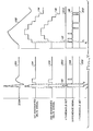
- FIG. 3 a timing diagram is shown of the various signals generated within the cardiac event detector 21 of the present invention.
- the R-wave 100 is shown on the left side of FIG. 3
- the VF waveform 102 is shown on the right side of FIG. 3 .
- Below each waveform are various other signals present within the cardiac event detector 21.
- the first integrated signal 104, and the second integrated signal 106 are shown as generated in response to the R-wave 100. From time t a to time t b , both of the integrated signals 104, 106 are shown as being equal in magnitude.
- the difference signal 108 is generated in response to the integrated signals (by the subtractor 60 as described above). From time t a to time t b , the difference signal is substantially zero in response to the equal integrated signals.
- the second integrated signal is generated based on the low-frequency clock signal, it is unable to quickly respond to the steep rise and fall (i.e., high slew rate) of the R-wave 100.
- the integrated signals are not equal, and therefore a non-zero difference signal 108 is generated.
- the difference signal will exhibit a peak 110 that exceeds either the high threshold signal 200 or the low threshold 202 signal.
- the detection signal (not shown) is generated, and thereby signals the occurrence of the R-wave 100 in the IEGM.
- the VF waveform 102 similarly causes the generation of the first and second integrated signals 114, 116.
- the low-frequency delta converter is better able respond to the VF waveform 102.
- the difference between the first integrated signal 114, and the second integrated signal 116 will be less than it was in response to the R-wave 100.
- the non-zero difference signal 121 will not be of sufficient magnitude to exceed either the high or low threshold signal 200, 202.
- the detection signal will not be generated in response to the VF waveform 102 being in the IEGM.
- FIG. 4 a graph is shown of an exemplary IEGM containing both R-waves, and VF waveforms, and showing an exemplary difference signal generated by the embodiment of FIG. 2 in response to the exemplary IEGM.
- the IEGM is represented on an upper horizontal axis 206, wherein voltage is shown as vertical displacement on the graph, and time is shown as horizontal displacement on the graph. From time t 0 to time t 1 the IEGM contains typical R-waves 208. On a lower horizontal axis 210 the difference signal generated by the subtractor 60 ( FIG. 2 ) is represented, wherein voltage is shown as vertical displacement on the graph, and time is shown as horizontal displacement on the graph.
- the difference signal voltage exhibits a distinct positive or negative spike 212 (or peak) that corresponds to each of the R-wave peaks in the IEGM on the upper horizontal axis 206.
- these voltage peaks cause the difference signal to exceed either the high or low threshold signal 200, 202, which in turn cause the generation of the detection signal as described above.
- the exemplary IEGM ceases to contain typical R-waves 208, and begins to contain ventricular fibrillation (VF) waveforms 214.
- the difference signal 216 ceases to exhibit the voltage peaks, instead maintaining a voltage level well within the window of voltages 204 centered around the lower horizontal axis 210. This peak-less signal 216 will not cause the generation of the detection signal.
- true R-waves 208 cause the generation of the event detection signal, but the event detection signal is not generated when VF waveforms 214 are present.
- the present invention can be characterized as a VF immune R-wave event detector.
- the present invention can be characterized as an improved ventricular fibrillation detector for use in an implantable cardioverter, defibrillator, or a combination device thereof.
- the present invention defines a non-zero difference signal which occurs in the absence of true R-waves as a reliable indicator of the presence of a VF waveform. Stated differently, VF waveforms are positively indicated when a non-zero difference signal is present that does not exceed either the high or the low threshold signal, as illustrated in FIGS. 3 and 4 .
- the present invention defines a "zero" difference signal as a quiescent baseline corresponding to the absence of true R-waves. For example, during asystole, no R-waves are generated, and the baseline is quiet. During bradycardia or when the heart is incompetent (and cannot raise its heart rate adequately in response to exercise), R-waves occur at very slow rate. Since VF is not present, the pacemaker senses only a quiescent baseline during its timing cycle. According to the present invention, the delta converters will tract each other and the difference signal will be zero while it samples the quiescent baseline. A zero difference signal is detected by the controller and will indicate to that pacing stimulation, not a shock, is required.
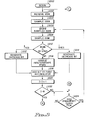
- FIGS. 5 and 6 a flowchart shows the steps traversed by the cardiac event detector 21 (of FIG. 2 ) for the high-frequency delta converter to produce the first integrated signal.
- the steps may instead be partially or completely traversed by a controller in response to a control program.
- the cardiac event detector 21 begins (block 1000) by receiving the IEGM (block 1002) from the amplifier 30 ( FIG. 2) .
- the system is initialized by digitally sampling the IEGM (block 1004), either within the high-frequency delta converter 46, or within the A/D converter (used in conjunction with the controller).
- the sampled IEGM is stored within the high-frequency delta converter 46, or within a memory that is a part of the controller (block 1006), and a second sample of the IEGM is made (block 1008).
- the increase bit is generated (block 1012), indicating that the IEGM is an increasing signal, by the high-frequency delta converter, or the controller. If the current IEGM sample is less than the previous IEGM sample by at least one step (block 1010), then the decrease bit is generated (block 1014), indicating that the IEGM is a decreasing signal. Finally, if the current IEGM sample does not differ from the previous IEGM sample by more than one step (block 1010), then the high-frequency delta converter, or controller will detect an indeterminate state (block 1016).
- the indeterminate state is handled, depending on the particular delta converter or controller/control program used, by generating either the increase bit, the decrease bit or a neutral bit.
- the high-frequency delta converter 46, or controller can alternate between generating the increase bit and the decrease bit until the current IEGM sample differs from the previous IEGM sample by more than one step.
- the increase bit or the decrease bit In the event either the increase bit or the decrease bit is generated, it will be added to a first accumulator within the high-frequency delta converter 46 or the controller (block 1018).
- the first accumulator generates an accumulator signal that is indicative of the bits that have been added to the accumulator.
- the increase bit causes an increase in the accumulator signal
- the decrease bit causes a decrease in the accumulator signal.
- the accumulator signal can be either a positive signal (when more increase bits than decrease bits have been added to the accumulator), or a negative signal (when more decrease bits than increase bit have been added to the accumulator).
- the accumulator signal may, e.g., be a four bit digital signal wherein one of the four bits indicates the sign (positive or negative), and the other three bits indicate the magnitude of the accumulator signal.
- a first iteration counter (that is also a part of the high-frequency delta converter, or controller) is incremented (block 1020), and if eight iterations have not recorded within the first iteration counter (block 1022), the high-frequency delta converter, or the controller, waits until the next clock cycle (block 1024), and returns to the step of storing the last IEGM sample (block 1006), and the steps that follow (blocks 1008 through 1022).
- the clock cycle is generated in response to the high-frequency clock signal described above.
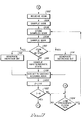
- FIG. 6 is a continuation of the flowchart of Fig. 5 .
- the first accumulator is read (block 1026), and the first delta signal is generated by the high-frequency delta converter, or the controller, in response to the accumulated bits in the first accumulator (block 1028).
- the first delta signal indicates whether the IEGM was an increasing signal or a decreasing signal, overall, during the delta cycle.
- the high-frequency delta converter, or controller clears the first iteration counter (block 1030), clears the first accumulator (block 1032), and waits until the next clock cycle (block 1024 of FIG. 5 ).
- the delta converter, or controller then returns to the step of storing the IEGM signal (block 1006 of Fig. 5 ), and continues to process (blocks 1006 through 1022 of FIG. 5 ) as described above.
- the first counter 56 is incremented in response to the first delta signal (block 1034).
- the first counter (or the controller) generates the first integrated signals in response to the first delta signals (blocks 1036).
- a parallel process is carried out by the low-frequency delta converter, or the controller.
- the steps traversed by the low-frequency delta converter, or controller, (blocks 1022 through 1134) are substantially the same as the steps traversed by the high-frequency delta converter, described above, except that the low-frequency delta converter utilizes the low-frequency clock signal, and therefore must wait a longer period between clock cycles (block 1124).
- the low-frequency delta converter may utilize the high-frequency clock signal, but wait for several (e.g., four) clock cycles before repeating steps (blocks 1106 through 1122) similar to those that are repeated by the high-frequency delta converter.
- the second counter 58 is incremented in response to the second delta signal (block 1134) that is generated by the low-frequency delta converter 48.
- the second counter (or the controller) generates the second integrated signals in response to the second delta signals (blocks 1136).
- FIG. 9 is a continuation of the flowcharts of FIGS. 6 and 8 which shows the steps traversed by the cardiac event detector 21 for determining the difference signal between the first and second integrated signals and, and produces the event detection signal when one of the threshold voltages is exceeded.
- the subtractor (or the controller) subtracts the first integrated signal from the second integrated signal (block 1038) and generates the difference signal (block 1040).
- the first comparator compares the difference signal to the high threshold signal (block 1042). In the event that the difference signal exceeds the high threshold signal, the high detect signal is generated, and in response thereto the "OR" gate generates the event detection signal (block 1044).
- the difference signal is also compared to the low threshold signal by the second comparator (block 1046), and in the event the difference signal exceeds the low threshold signal, the low detect signal is generated by the second comparator, or controller, and in response thereto the "OR" gate generates the detection signal (block 1048).
- the event detection signal is generated whenever the R-wave is present, and the event detection signal is not generated whenever the VF waveform is present.
- Ventricular fibrillation may be observed by recognizing that the high speed and low speed delta converters/accumulators contain the same magnitude (within some tolerance).
Landscapes
- Health & Medical Sciences (AREA)
- Cardiology (AREA)
- Life Sciences & Earth Sciences (AREA)
- Heart & Thoracic Surgery (AREA)
- Nuclear Medicine, Radiotherapy & Molecular Imaging (AREA)
- Engineering & Computer Science (AREA)
- Biomedical Technology (AREA)
- Radiology & Medical Imaging (AREA)
- Animal Behavior & Ethology (AREA)
- General Health & Medical Sciences (AREA)
- Public Health (AREA)
- Veterinary Medicine (AREA)
- Physiology (AREA)
- Biophysics (AREA)
- Electrotherapy Devices (AREA)
- Measurement And Recording Of Electrical Phenomena And Electrical Characteristics Of The Living Body (AREA)
Applications Claiming Priority (2)
| Application Number | Priority Date | Filing Date | Title |
|---|---|---|---|
| US08/567,658 US5623936A (en) | 1995-12-05 | 1995-12-05 | Implantable medical device having means for discriminating between true R-waves and ventricular fibrillation |
| US567658 | 1995-12-05 |
Publications (2)
| Publication Number | Publication Date |
|---|---|
| EP0778050A2 true EP0778050A2 (fr) | 1997-06-11 |
| EP0778050A3 EP0778050A3 (fr) | 1998-09-23 |
Family
ID=24268093
Family Applications (1)
| Application Number | Title | Priority Date | Filing Date |
|---|---|---|---|
| EP96308762A Withdrawn EP0778050A3 (fr) | 1995-12-05 | 1996-12-04 | Dispositif médical implantable avec un système de détection d'évènements cardioques |
Country Status (3)
| Country | Link |
|---|---|
| US (1) | US5623936A (fr) |
| EP (1) | EP0778050A3 (fr) |
| JP (1) | JPH09173476A (fr) |
Families Citing this family (12)
| Publication number | Priority date | Publication date | Assignee | Title |
|---|---|---|---|---|
| WO1999059673A1 (fr) | 1998-05-21 | 1999-11-25 | Medtronic Physio-Control Manufacturing Corp. | Detection et signalisation automatique d'une asystole cardiaque |
| DE10114724A1 (de) * | 2001-03-21 | 2002-09-26 | Biotronik Mess & Therapieg | Vorrichtung zur Charakterisierung des Myokardzustands |
| CA2481631A1 (fr) * | 2004-09-15 | 2006-03-15 | Dspfactory Ltd. | Methode et systeme de traitement des signaux physiologiques |
| US7430448B1 (en) * | 2005-09-01 | 2008-09-30 | Pacesetter, Inc. | Implantable cardiac device providing intrinsic conduction search with premature atrial contraction protection and method |
| EP2081618B1 (fr) | 2006-10-13 | 2016-01-06 | Bluesky Medical Group Inc. | Circuit de contrôle et appareil améliorés pour le traitement des plaies par dépression |
| US8504144B2 (en) | 2007-07-11 | 2013-08-06 | Pacesetter, Inc. | Systems and methods for employing multiple filters to detect T-wave oversensing and to improve tachyarrhythmia detection within an implantable medical device |
| US8260404B1 (en) | 2007-07-11 | 2012-09-04 | Pacesetter, Inc. | Systems and methods for employing multiple filters to detect T-wave oversensing and to improve tachyarrhythmia detection within an implantable medical device |
| US7813791B1 (en) | 2007-08-20 | 2010-10-12 | Pacesetter, Inc. | Systems and methods for employing an FFT to distinguish R-waves from T-waves using an implantable medical device |
| US8682450B2 (en) | 2012-07-31 | 2014-03-25 | Pacesetter, Inc. | Systems and methods for controlling neurostimulation of acupuncture sites using an implantable cardiac rhythm management device |
| CN103869125B (zh) * | 2012-12-10 | 2018-09-25 | 北京普源精电科技有限公司 | 一种具有录制波形分析功能的示波器 |
| CN113786200B (zh) * | 2020-05-28 | 2022-10-11 | 深圳邦健生物医疗设备股份有限公司 | 心电信号处理方法、装置、设备及可读介质 |
| EP3988162B1 (fr) * | 2020-10-23 | 2022-12-07 | Osypka Medical GmbH | Technique de commande du fonctionnement d'un stimulateur cardiaque réglable par l'utilisateur ou d'un modèle logiciel associé en mode d'entraînement |
Citations (18)
| Publication number | Priority date | Publication date | Assignee | Title |
|---|---|---|---|---|
| US4181133A (en) | 1978-05-22 | 1980-01-01 | Arco Medical Products Company | Programmable tachycardia pacer |
| US4280502A (en) | 1979-08-08 | 1981-07-28 | Intermedics, Inc. | Tachycardia arrester |
| US4442459A (en) | 1979-03-03 | 1984-04-10 | Canon Kabushiki Kaisha | Facsimile transceiver |
| US4493325A (en) | 1982-05-03 | 1985-01-15 | Medtronic, Inc. | Tachyarrhythmia pacer |
| US4552154A (en) | 1984-03-12 | 1985-11-12 | Medtronic, Inc. | Waveform morphology discriminator and method |
| US4630204A (en) | 1984-02-21 | 1986-12-16 | Mortara Instrument Inc. | High resolution ECG waveform processor |
| US4686989A (en) | 1985-05-16 | 1987-08-18 | Nicholas P. D. Smyth | Method of operating pacemaker for detecting pacemaker-mediated tachycardia |
| US4790317A (en) | 1985-10-25 | 1988-12-13 | Davies David W | Apparatus for recognition and termination of ventricular tachycardia and ventricular fibrillation |
| US4830006A (en) | 1986-06-17 | 1989-05-16 | Intermedics, Inc. | Implantable cardiac stimulator for detection and treatment of ventricular arrhythmias |
| US4880004A (en) | 1988-06-07 | 1989-11-14 | Intermedics, Inc. | Implantable cardiac stimulator with automatic gain control and bandpass filtering in feedback loop |
| US4880005A (en) | 1985-08-12 | 1989-11-14 | Intermedics, Inc. | Pacemaker for detecting and terminating a tachycardia |
| US4905708A (en) | 1985-10-31 | 1990-03-06 | Davies David W | Apparatus for recognizing cardiac rhythms |
| US4969465A (en) | 1989-05-19 | 1990-11-13 | Ventritex, Inc. | Cardiac therapy method |
| US5103822A (en) | 1990-04-03 | 1992-04-14 | Siemens-Pacesetter, Inc. | Pacing system for termination of cardiac arrhythmias utilizing scanning techniques |
| US5161527A (en) | 1991-02-13 | 1992-11-10 | Telectronics Pacing Systems, Inc. | Apparatus and method for detecting abnormal cardiac rhythms in dual chamber arrhythmia control system |
| US5188105A (en) | 1990-11-14 | 1993-02-23 | Medtronic, Inc. | Apparatus and method for treating a tachyarrhythmia |
| US5205283A (en) | 1991-07-30 | 1993-04-27 | Medtronic, Inc. | Method and apparatus for tachyarrhythmia detection and treatment |
| US5217021A (en) | 1991-07-30 | 1993-06-08 | Telectronics Pacing Systems, Inc. | Detection of cardiac arrhythmias using correlation of a cardiac electrical signals and temporal data compression |
Family Cites Families (9)
| Publication number | Priority date | Publication date | Assignee | Title |
|---|---|---|---|---|
| US4000461A (en) * | 1973-10-04 | 1976-12-28 | Textronix, Inc. | R-wave detector |
| US3858034A (en) * | 1973-10-19 | 1974-12-31 | Del Mar Eng Lab | Electrocardiac computer |
| DE2628629C3 (de) * | 1976-06-25 | 1981-07-23 | Irnich, Werner, Dr.-Ing., 5100 Aachen | Bedarfsherzschrittmacher mit Störerkennungsschaltung |
| US4296755A (en) * | 1980-03-19 | 1981-10-27 | Datamedix Inc. | Method and apparatus for determining ventricular fibrillation |
| US4393877A (en) * | 1981-05-15 | 1983-07-19 | Mieczyslaw Mirowski | Heart rate detector |
| US4458692A (en) * | 1982-02-11 | 1984-07-10 | Arrhythmia Research Technology, Inc. | System and method for predicting ventricular tachycardia with a gain controlled high pass filter |
| US4509529A (en) * | 1982-06-30 | 1985-04-09 | Telectronics Pty. Ltd. | Physiological event recognition techniques for use with a delta modulator |
| US4478224A (en) * | 1982-11-26 | 1984-10-23 | Camino Laboratories, Inc. | Artifact detector for heartbeat rate measuring system |
| US4799493A (en) * | 1987-03-13 | 1989-01-24 | Cardiac Pacemakers, Inc. | Dual channel coherent fibrillation detection system |
-
1995
- 1995-12-05 US US08/567,658 patent/US5623936A/en not_active Expired - Lifetime
-
1996
- 1996-12-04 JP JP8339004A patent/JPH09173476A/ja active Pending
- 1996-12-04 EP EP96308762A patent/EP0778050A3/fr not_active Withdrawn
Patent Citations (20)
| Publication number | Priority date | Publication date | Assignee | Title |
|---|---|---|---|---|
| US4181133A (en) | 1978-05-22 | 1980-01-01 | Arco Medical Products Company | Programmable tachycardia pacer |
| US4442459A (en) | 1979-03-03 | 1984-04-10 | Canon Kabushiki Kaisha | Facsimile transceiver |
| US4280502A (en) | 1979-08-08 | 1981-07-28 | Intermedics, Inc. | Tachycardia arrester |
| US4493325A (en) | 1982-05-03 | 1985-01-15 | Medtronic, Inc. | Tachyarrhythmia pacer |
| US4630204A (en) | 1984-02-21 | 1986-12-16 | Mortara Instrument Inc. | High resolution ECG waveform processor |
| US4552154A (en) | 1984-03-12 | 1985-11-12 | Medtronic, Inc. | Waveform morphology discriminator and method |
| US4686989A (en) | 1985-05-16 | 1987-08-18 | Nicholas P. D. Smyth | Method of operating pacemaker for detecting pacemaker-mediated tachycardia |
| US4880005A (en) | 1985-08-12 | 1989-11-14 | Intermedics, Inc. | Pacemaker for detecting and terminating a tachycardia |
| US4880005B1 (en) | 1985-08-12 | 1996-10-29 | Intermedics Inc | Pacemaker for detecting and terminating a tachycardia |
| US4790317A (en) | 1985-10-25 | 1988-12-13 | Davies David W | Apparatus for recognition and termination of ventricular tachycardia and ventricular fibrillation |
| US4905708A (en) | 1985-10-31 | 1990-03-06 | Davies David W | Apparatus for recognizing cardiac rhythms |
| US4830006A (en) | 1986-06-17 | 1989-05-16 | Intermedics, Inc. | Implantable cardiac stimulator for detection and treatment of ventricular arrhythmias |
| US4830006B1 (en) | 1986-06-17 | 1997-10-28 | Intermedics Inc | Implantable cardiac stimulator for detection and treatment of ventricular arrhythmias |
| US4880004A (en) | 1988-06-07 | 1989-11-14 | Intermedics, Inc. | Implantable cardiac stimulator with automatic gain control and bandpass filtering in feedback loop |
| US4969465A (en) | 1989-05-19 | 1990-11-13 | Ventritex, Inc. | Cardiac therapy method |
| US5103822A (en) | 1990-04-03 | 1992-04-14 | Siemens-Pacesetter, Inc. | Pacing system for termination of cardiac arrhythmias utilizing scanning techniques |
| US5188105A (en) | 1990-11-14 | 1993-02-23 | Medtronic, Inc. | Apparatus and method for treating a tachyarrhythmia |
| US5161527A (en) | 1991-02-13 | 1992-11-10 | Telectronics Pacing Systems, Inc. | Apparatus and method for detecting abnormal cardiac rhythms in dual chamber arrhythmia control system |
| US5205283A (en) | 1991-07-30 | 1993-04-27 | Medtronic, Inc. | Method and apparatus for tachyarrhythmia detection and treatment |
| US5217021A (en) | 1991-07-30 | 1993-06-08 | Telectronics Pacing Systems, Inc. | Detection of cardiac arrhythmias using correlation of a cardiac electrical signals and temporal data compression |
Also Published As
| Publication number | Publication date |
|---|---|
| JPH09173476A (ja) | 1997-07-08 |
| EP0778050A3 (fr) | 1998-09-23 |
| US5623936A (en) | 1997-04-29 |
Similar Documents
| Publication | Publication Date | Title |
|---|---|---|
| US20240148307A1 (en) | Implantable cardioverter-defibrillator (icd) tachyarrhythmia detection modifications responsive to detected pacing | |
| US7076289B2 (en) | Methods and apparatus for discriminating polymorphic tachyarrhythmias from monomorphic tachyarrhythmias facilitating detection of fibrillation | |
| US7774063B2 (en) | Method and apparatus for discriminating cardiac signals in a medical device based on wavelet decomposition analysis | |
| US7130677B2 (en) | Methods and apparatus for discriminating polymorphic tachyarrhythmias from monomorphic tachyarrhythmias facilitating detection of fibrillation | |
| US6810283B2 (en) | Multiple templates for filtering of far field R-waves | |
| US8792971B2 (en) | Method and apparatus for identifying oversensing using far-field intracardiac electrograms and marker channels | |
| US5560369A (en) | Cardiac arrhythmia detection system for an implantable stimulation device and method | |
| US7130681B2 (en) | Use of accelerometer signal to augment ventricular arrhythmia detection | |
| US7103405B2 (en) | Methods and apparatus for discriminating polymorphic tachyarrhythmias from monomorphic tachyarrhythmias facilitating detection of fibrillation | |
| US8332022B2 (en) | Methods and apparatus for discriminating polymorphic tachyarrhythmias from monomorphic tachyarrhythmias facilitating detection of fibrillation | |
| US6556859B1 (en) | System and method for classifying sensed atrial events in a cardiac pacing system | |
| CA2517293A1 (fr) | Detection de l'arret de la tachyarhytmie | |
| US5623936A (en) | Implantable medical device having means for discriminating between true R-waves and ventricular fibrillation | |
| US6434426B1 (en) | Method and system for determining a noise floor in a cardiac pacing system | |
| EP1585443A2 (fr) | Repereur d'alternances des ondes t | |
| Shin et al. | Development of Arrhythmia Diagnosis Algorithm for Effective Control of Antitachycardia Pacing and High Energy Shock of ICD |
Legal Events
| Date | Code | Title | Description |
|---|---|---|---|
| PUAI | Public reference made under article 153(3) epc to a published international application that has entered the european phase |
Free format text: ORIGINAL CODE: 0009012 |
|
| AK | Designated contracting states |
Kind code of ref document: A2 Designated state(s): DE ES FR GB IT NL |
|
| PUAL | Search report despatched |
Free format text: ORIGINAL CODE: 0009013 |
|
| AK | Designated contracting states |
Kind code of ref document: A3 Designated state(s): DE ES FR GB IT NL |
|
| STAA | Information on the status of an ep patent application or granted ep patent |
Free format text: STATUS: THE APPLICATION IS DEEMED TO BE WITHDRAWN |
|
| 18D | Application deemed to be withdrawn |
Effective date: 19990701 |