EP0778105A1 - Centrage d'un appareil de soudage orbital - Google Patents
Centrage d'un appareil de soudage orbital Download PDFInfo
- Publication number
- EP0778105A1 EP0778105A1 EP95308946A EP95308946A EP0778105A1 EP 0778105 A1 EP0778105 A1 EP 0778105A1 EP 95308946 A EP95308946 A EP 95308946A EP 95308946 A EP95308946 A EP 95308946A EP 0778105 A1 EP0778105 A1 EP 0778105A1
- Authority
- EP
- European Patent Office
- Prior art keywords
- pilot
- probe unit
- welding
- welding apparatus
- balls
- Prior art date
- Legal status (The legal status is an assumption and is not a legal conclusion. Google has not performed a legal analysis and makes no representation as to the accuracy of the status listed.)
- Granted
Links
- 238000003466 welding Methods 0.000 title claims abstract description 62
- 239000000523 sample Substances 0.000 title claims abstract description 43
- 230000000717 retained effect Effects 0.000 claims 2
- 238000010891 electric arc Methods 0.000 abstract description 4
- 239000011261 inert gas Substances 0.000 abstract description 2
- 238000000034 method Methods 0.000 abstract 1
- 230000006835 compression Effects 0.000 description 4
- 238000007906 compression Methods 0.000 description 4
- 239000002184 metal Substances 0.000 description 4
- 229910052751 metal Inorganic materials 0.000 description 4
- 230000037431 insertion Effects 0.000 description 3
- 238000003780 insertion Methods 0.000 description 3
- 229910001369 Brass Inorganic materials 0.000 description 2
- 239000010951 brass Substances 0.000 description 2
- 238000010276 construction Methods 0.000 description 2
- 239000007789 gas Substances 0.000 description 2
- 239000010935 stainless steel Substances 0.000 description 2
- WFKWXMTUELFFGS-UHFFFAOYSA-N tungsten Chemical compound [W] WFKWXMTUELFFGS-UHFFFAOYSA-N 0.000 description 2
- 239000010937 tungsten Substances 0.000 description 2
- 229910052721 tungsten Inorganic materials 0.000 description 2
- 229910000975 Carbon steel Inorganic materials 0.000 description 1
- RYGMFSIKBFXOCR-UHFFFAOYSA-N Copper Chemical compound [Cu] RYGMFSIKBFXOCR-UHFFFAOYSA-N 0.000 description 1
- 229910000760 Hardened steel Inorganic materials 0.000 description 1
- 229910001069 Ti alloy Inorganic materials 0.000 description 1
- 239000011324 bead Substances 0.000 description 1
- 239000010962 carbon steel Substances 0.000 description 1
- 238000001816 cooling Methods 0.000 description 1
- 239000010949 copper Substances 0.000 description 1
- 229910052802 copper Inorganic materials 0.000 description 1
- 230000007812 deficiency Effects 0.000 description 1
- 230000004927 fusion Effects 0.000 description 1
- 239000003779 heat-resistant material Substances 0.000 description 1
- 230000001788 irregular Effects 0.000 description 1
- 239000007787 solid Substances 0.000 description 1
- 229910001220 stainless steel Inorganic materials 0.000 description 1
- 229910001256 stainless steel alloy Inorganic materials 0.000 description 1
Images


Classifications
-
- B—PERFORMING OPERATIONS; TRANSPORTING
- B23—MACHINE TOOLS; METAL-WORKING NOT OTHERWISE PROVIDED FOR
- B23K—SOLDERING OR UNSOLDERING; WELDING; CLADDING OR PLATING BY SOLDERING OR WELDING; CUTTING BY APPLYING HEAT LOCALLY, e.g. FLAME CUTTING; WORKING BY LASER BEAM
- B23K9/00—Arc welding or cutting
- B23K9/02—Seam welding; Backing means; Inserts
- B23K9/028—Seam welding; Backing means; Inserts for curved planar seams
- B23K9/0288—Seam welding; Backing means; Inserts for curved planar seams for welding of tubes to tube plates
Definitions
- This invention pertains to welding apparatus adapted for welding tubes into a tubesheet. It pertains particularly to such welding apparatus having an improved pilot probe containing grooves or spring-loaded projections for locating a welding torch precisely relative to a tube being welded leak-tightly into a tubesheet.
- the invention provides an improved orbital welding apparatus or torch specially adapted for rapidly welding tube ends into a tubesheet.
- the apparatus provides for precise location of the torch electrode relative to the tube end during such welding operations.
- the invention includes an orbital welding torch body containing a rotor unit, a welding electrode attached to the rotor unit and being adapted for making successive GTA (gas tungsten arc) welds of tubes into a tubehseet, and a pilot-probe unit extending downwardly from the lower side of the torch body and being adapted for insertion into a tube-to-be-welded to locate the torch body and welding electrode relative to the tube-to-be-welded.
- GTA gas tungsten arc
- the pilot probe unit is generally cylindrical and is provided with a plurality of resiliently-mounted convex lateral projections such as spring-loaded balls, which are spaced apart both circumferentially and longitudinally from adjacent projections or balls.
- Such resiliently-mounted projections serve to automatically center the pilot probe unit within a tube-to-be-welded even if the tube is not entirely round.
- Such convex projections may be resiliently-mounted in opposite pairs by a compression spring located in transverse openings provided in the pilot probe unit.
- the convex surfaces or balls each extend radially outwardly from the pilot outer surface by at least 0.008 inch, and preferably 0.012-0.060 inches.
- the pilot probe unit containing a plurality of resiliently mounted convex projections or balls is inserted manually into a tube-to-be-welded into a tubesheet, so that the resiliently-mounted surfaces firmly contact the inner surface of the tube.
- the pilot probe unit is thereby accurately centered within the tube by action of the resiliently mounted surfaces. The centering is accomplished prior to welding the tube end to the tubesheet.
- the apparatus accommodates variations in the tube inner surface.
- the torch apparatus rotor mechanism is then actuated, and the welding electrode produces a metal arc weld between the tube end and the tubesheet.
- the pilot probe unit may be a solid cylinder having a plurality of transverse grooves.
- the invention is shown and described with reference to simple fusion welding, it may he used with fillet welding with welding wire addition.
- This invention is useful on welding machines that commonly weld metal tubes having outside diameters of about 0.50 to 2.0 inches into tubesheets.
- the invention is useful for arc welding tubing made of brass, copper, carbon steel, stainless steel, and titanium alloy into tubesheets.
- the present invention advantageously provides an improved orbital type welding apparatus containing a pilot probe device which produces more accurate alignment for the gas shielded electrode of welding torches, and results in making more rapid and reliable welds of tubes into tubesheets.
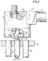
- a welding torch assembly 10 includes a body unit 12 having a handle 13, and internal rotor 14, a welding head unit 16 containing a gas-shielded tungsten electrode 17, and a pilot probe unit 20 extending downwardly from the lower side of the body 12.
- the pilot probe unit 20 is attached to torch rotor 14 by a locater arm 18, which has a portion 19 that is offset from the rotor 14 centerline, so as to provide a horizontal distance (d) between the electrode 17 and the center of the offset portion 19.
- the distance (d) is substantially equal to the outside radius of a tube 30 to be welded into a tubesheet 32 plus a typical weld site offset of, for example, ten thousandths (0.010) of an inch.
- the rotor and electrode units of the welding apparatus are described in greater detail in U.S. Patent No. 3,946,191, which is incorporated herein by reference to the extent necessary for providing a complete description of this invention.
- the electrode 17 of torch unit 16 will travel around the circumference of the tube end 31 so as to weld it pressure-tightly into the tubesheet 32.
- an elongated mandrel 22 is attached to extension 19 of torch locater arm 18 by means of a central connecting rod 21 having an upper cross-pin 23 inserted into a transverse hole which intersects the arm extension 19 and central centering rod 21.
- the central rod 21 is inserted into and rotatably attached to the upper end of elongated mandrel 22 by a lower transverse pin 25 which fits into a circular groove 25a in rod 21.
- Fig. 4 shows an enlarged cross-sectional view of the construction used for securely and removably attaching the central connecting rod 21 into arm extension 19, and Fig. 5 shows the construction for attaching the elongated outer mandrel 22 to the central connecting rod 21 and to welding torch assembly 10.
- Such attachment means permits removal of the pilot probe unit 20 from the welding apparatus 10 whenever needed.
- pins 23 and 25, and groove 25a may be combined at the illustrated location of pin 23, and the central connecting rod 21 may be made unitary with mandrel 22.
- the elongated mandrel 22 is provided with a plurality of convex resiliently-mounted projections or balls 24, which are substantially uniformly spaced apart along the surface of the mandrel.
- These balls are preferably provided in sets, each set being spring-loaded by a compression spring 26 set in transverse openings 27.
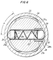
- Each transverse opening 27 has a smaller diameter portion 27a sized to retain the ball 24, so that the balls each extend radially outwardly from the outer surface of mandrel 22 by 0.008-0.060 inches.
- the balls each press outwardly against the inner wall of tube 30 across a clearance 30a between the outer surface of mandrel 22 and the inner wall of tube 30, thereby providing for the pilot probe unit 20 to be centrally located with the tube 30 being welded into tubesheet 32.
- the spring loaded balls 24 are substantially evenly spaced apart both circumferentially and longitudinally of the mandrel 22.
- one ball 24 of each set is preferably located in a small diameter portion 27a diametrically opposite a threaded member 28, which is threaded into an enlarged portion 27b at the other end of transverse opening 27.
- Threaded member 28 is provided with a small diameter portion 28a to retain its own ball 24.
- the sets of two spring-loaded balls 24 and threaded member 28 are spaced apart longitudinally along the mandrel 22 by a distance which may advantageously be in a range between about 0.5 and 4.0 times the outside diameter of the mandrel
- At least four and preferably six to eight sets of spring-loaded balls longitudinally spaced apart are used in mandrel 22 of pilot 20, with adjacent sets of balls having central axes that are angled from each other by an angle A of at least 30 degrees, and preferably 45-90 degrees.
- the mandrel 22 is usually made of metal having good heat conduction and machinability characteristics, such as brass.
- Balls 24 are usually made of hardened steel for good wear resistance.
- the compression springs 26 the spring rates are selected so as to permit ease of insertion of the probe into a tube to be welded, i.e. springs not too stiff, and providing adequate stability of the probe unit in the tube, i.e. springs not too weak.
- the compression springs 26 are preferably made of a heat-resistant material such as stainless steel.
- the pilot probe unit 20 of welder apparatus 10 is inserted manually into a tube 30, and the apparatus 10 is lowered until it contacts the work.
- the tube 30 has an inner diameter which is 0.020-0.040 inch greater than the outside diameter of mandrel 22, so that the action of the multiple spring-loaded balls 24 centers the pilot 20 in the tube 30, even though the inside of the tube may not be perfectly round.
- the pilot probe 20 thereby provides for the electrode 17 to be accurately aligned with the end 31 of tube 30, even if the tube is somewhat out-of-round or otherwise dimensionally irregular.
- the welding torch is then operated by providing inert gas shielding for the electrode 17, striking an electric arc between the electrode 17 tip end and tube end 31, then rotating the welding head unit 16 in a circular orbit around the pilot unit 20 so as to melt the tube end 31 and weld it onto the tubesheet 32.
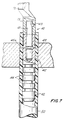
- the pilot probe unit may be provided with a plurality of transverse grooves, as is shown in Fig. 7.
- This embodiment of the pilot probe unit is useful for tube welding applications in which the tubes to be welded are essentially round and have uniform wall thickness.
- the pilot probe unit 40 includes an elongated mandrel 42 which is attached to arm extension 19 by means of a central connecting rod 41 having an upper cross pin 43.
- the central rod 41 is also inserted into and rotatably attached to the upper end of elongated mandrel 42 by means of transverse pin 45 which fits into circular groove 45a in the rod 44.
- the elongated mandrel 42 contains a plurality of transverse grooves 44, which serve to facilitate insertion of the pilot 40 into a tube 50 to be welded, and also advantageously reduces weight and improves air cooling of the pilot probe unit.
- the grooves 44 are each typically 0.12-0.15 inch wide as measured longitudinally, may be cut to a radial depth of about 0.25 inch, and are spaced apart by 0.18-0.22 inches. The difference between the diameter of mandrel 42 and the inside diameter of tube 50 should be 0.003-0.005 inches for good welding results.
- a heat exchanger has a plurality of metal tubes inserted into a tubesheet preparatory to welding the tube ends to the tubesheet.
- An orbital type welding apparatus such as Hobart Model No. 550, but having a pilot unit according to the current invention containing six sets of spring loaded balls, is inserted into one of the tubes, so that the welder electrode is closely aligned with the tube end adjacent the opening in the tubesheet.
- the welding apparatus is operated so that an electric arc is struck between the electrode and the tube, and a weld bead is formed circumferentially between the tube end and tubesheet.
- the welding apparatus is then removed and inserted successively into adjacent tubes, and the welding operation continued.
Landscapes
- Engineering & Computer Science (AREA)
- Physics & Mathematics (AREA)
- Plasma & Fusion (AREA)
- Mechanical Engineering (AREA)
- Butt Welding And Welding Of Specific Article (AREA)
Priority Applications (2)
| Application Number | Priority Date | Filing Date | Title |
|---|---|---|---|
| EP19950308946 EP0778105B1 (fr) | 1995-12-08 | 1995-12-08 | Centrage d'un appareil de soudage orbital |
| DE1995617431 DE69517431T2 (de) | 1995-12-08 | 1995-12-08 | Zentrierfutter einer Orbitalschweissvorrichtung |
Applications Claiming Priority (1)
| Application Number | Priority Date | Filing Date | Title |
|---|---|---|---|
| EP19950308946 EP0778105B1 (fr) | 1995-12-08 | 1995-12-08 | Centrage d'un appareil de soudage orbital |
Publications (2)
| Publication Number | Publication Date |
|---|---|
| EP0778105A1 true EP0778105A1 (fr) | 1997-06-11 |
| EP0778105B1 EP0778105B1 (fr) | 2000-06-07 |
Family
ID=8221428
Family Applications (1)
| Application Number | Title | Priority Date | Filing Date |
|---|---|---|---|
| EP19950308946 Expired - Lifetime EP0778105B1 (fr) | 1995-12-08 | 1995-12-08 | Centrage d'un appareil de soudage orbital |
Country Status (2)
| Country | Link |
|---|---|
| EP (1) | EP0778105B1 (fr) |
| DE (1) | DE69517431T2 (fr) |
Citations (3)
| Publication number | Priority date | Publication date | Assignee | Title |
|---|---|---|---|---|
| CH408229A (de) * | 1961-09-02 | 1966-02-28 | Linde Ag | Vorrichtung zum Einschweissen eines hohlzylindrischen Körpers in eine Bohrung eines Werkstückes |
| US3754114A (en) * | 1971-04-14 | 1973-08-21 | J Peyrot | Rotatable welding gun |
| EP0321317A2 (fr) * | 1987-11-13 | 1989-06-21 | Framatome | Dispositif de soudage de l'extrémité d'une pièce tubulaire fixée à l'intérieur d'un alésage débouchant sur une face d'une plaque telle qu'une plaque tubulaire de générateur de vapeur |
-
1995
- 1995-12-08 DE DE1995617431 patent/DE69517431T2/de not_active Expired - Fee Related
- 1995-12-08 EP EP19950308946 patent/EP0778105B1/fr not_active Expired - Lifetime
Patent Citations (3)
| Publication number | Priority date | Publication date | Assignee | Title |
|---|---|---|---|---|
| CH408229A (de) * | 1961-09-02 | 1966-02-28 | Linde Ag | Vorrichtung zum Einschweissen eines hohlzylindrischen Körpers in eine Bohrung eines Werkstückes |
| US3754114A (en) * | 1971-04-14 | 1973-08-21 | J Peyrot | Rotatable welding gun |
| EP0321317A2 (fr) * | 1987-11-13 | 1989-06-21 | Framatome | Dispositif de soudage de l'extrémité d'une pièce tubulaire fixée à l'intérieur d'un alésage débouchant sur une face d'une plaque telle qu'une plaque tubulaire de générateur de vapeur |
Also Published As
| Publication number | Publication date |
|---|---|
| DE69517431T2 (de) | 2000-10-12 |
| EP0778105B1 (fr) | 2000-06-07 |
| DE69517431D1 (de) | 2000-07-13 |
Similar Documents
| Publication | Publication Date | Title |
|---|---|---|
| US4238117A (en) | Railing and method of making the same | |
| US4943001A (en) | Tube-type vessel having crevice-free joints and method for manufacturing the same | |
| US5486670A (en) | Pilot probe for orbital welding apparatus | |
| US3440391A (en) | Internal tube welding | |
| EP0778105A1 (fr) | Centrage d'un appareil de soudage orbital | |
| US7476824B2 (en) | Welding apparatus for resistance welding heat exchanger tube to tubesheet | |
| CN107052536B (zh) | 一种无填充材料的低合金钢换热管对接自动焊接工艺 | |
| CN111069775B (zh) | 一种换热管与管板的连接系统及方法 | |
| US7650772B2 (en) | Rotary flaring tool and method of use | |
| US5483033A (en) | Apparatus and method for sequentially registering tool modules for a welding operation of a tube | |
| ES2189896T3 (es) | Procedimiento para reparar tubos intercambiadores de calor. | |
| US4264801A (en) | Method of welding tube to header of heat exchanger | |
| US7253372B2 (en) | Method for welding heat exchanger tube to tubesheet | |
| US3824663A (en) | Method of welding a tube to a tube sheet | |
| US3205340A (en) | Welding of tubes | |
| CN111702358B (zh) | 一种ct管钛窗螺钉焊接方法及焊接设备 | |
| CN2225928Y (zh) | 多功能凸焊枪 | |
| CN210475809U (zh) | 一种焊缝焊接轨迹检测装置 | |
| JP3940519B2 (ja) | シール溶接装置 | |
| CN111098004A (zh) | 一种手工钨极氩弧焊焊炬及狭小空间焊道的分道焊接方法 | |
| US4575971A (en) | Device for holding and aiding in the sharpening of welding rods | |
| CA1305344C (fr) | Methode d'enlevement non destructive des tubes d'un echangeur de chaleur et outil connexe | |
| CN115971620B (zh) | 一种换热器管板管头焊缝手工钨极氩弧焊辅助装置 | |
| CA1063949A (fr) | Marteau et machine a souder pneumatique | |
| CN1124187A (zh) | 轨道式焊接装置的导向头 |
Legal Events
| Date | Code | Title | Description |
|---|---|---|---|
| PUAI | Public reference made under article 153(3) epc to a published international application that has entered the european phase |
Free format text: ORIGINAL CODE: 0009012 |
|
| AK | Designated contracting states |
Kind code of ref document: A1 Designated state(s): DE FR GB |
|
| 17P | Request for examination filed |
Effective date: 19971211 |
|
| 17Q | First examination report despatched |
Effective date: 19980917 |
|
| GRAG | Despatch of communication of intention to grant |
Free format text: ORIGINAL CODE: EPIDOS AGRA |
|
| GRAG | Despatch of communication of intention to grant |
Free format text: ORIGINAL CODE: EPIDOS AGRA |
|
| GRAG | Despatch of communication of intention to grant |
Free format text: ORIGINAL CODE: EPIDOS AGRA |
|
| GRAH | Despatch of communication of intention to grant a patent |
Free format text: ORIGINAL CODE: EPIDOS IGRA |
|
| GRAH | Despatch of communication of intention to grant a patent |
Free format text: ORIGINAL CODE: EPIDOS IGRA |
|
| GRAA | (expected) grant |
Free format text: ORIGINAL CODE: 0009210 |
|
| AK | Designated contracting states |
Kind code of ref document: B1 Designated state(s): DE FR GB |
|
| REF | Corresponds to: |
Ref document number: 69517431 Country of ref document: DE Date of ref document: 20000713 |
|
| ET | Fr: translation filed | ||
| PGFP | Annual fee paid to national office [announced via postgrant information from national office to epo] |
Ref country code: DE Payment date: 20001116 Year of fee payment: 6 |
|
| PGFP | Annual fee paid to national office [announced via postgrant information from national office to epo] |
Ref country code: FR Payment date: 20001117 Year of fee payment: 6 |
|
| PGFP | Annual fee paid to national office [announced via postgrant information from national office to epo] |
Ref country code: GB Payment date: 20001121 Year of fee payment: 6 |
|
| PLBE | No opposition filed within time limit |
Free format text: ORIGINAL CODE: 0009261 |
|
| STAA | Information on the status of an ep patent application or granted ep patent |
Free format text: STATUS: NO OPPOSITION FILED WITHIN TIME LIMIT |
|
| 26N | No opposition filed | ||
| PG25 | Lapsed in a contracting state [announced via postgrant information from national office to epo] |
Ref country code: GB Free format text: LAPSE BECAUSE OF NON-PAYMENT OF DUE FEES Effective date: 20011208 |
|
| REG | Reference to a national code |
Ref country code: GB Ref legal event code: IF02 |
|
| PG25 | Lapsed in a contracting state [announced via postgrant information from national office to epo] |
Ref country code: DE Free format text: LAPSE BECAUSE OF NON-PAYMENT OF DUE FEES Effective date: 20020702 |
|
| GBPC | Gb: european patent ceased through non-payment of renewal fee |
Effective date: 20011208 |
|
| PG25 | Lapsed in a contracting state [announced via postgrant information from national office to epo] |
Ref country code: FR Free format text: LAPSE BECAUSE OF NON-PAYMENT OF DUE FEES Effective date: 20020830 |
|
| REG | Reference to a national code |
Ref country code: FR Ref legal event code: ST |