EP0778124A2 - Vorrichtung und Verfahren zur Ausführung eines veränderbaren Drucks auf eine Fläche bei der Herstellung von Doppelwelpappen - Google Patents
Vorrichtung und Verfahren zur Ausführung eines veränderbaren Drucks auf eine Fläche bei der Herstellung von Doppelwelpappen Download PDFInfo
- Publication number
- EP0778124A2 EP0778124A2 EP96102481A EP96102481A EP0778124A2 EP 0778124 A2 EP0778124 A2 EP 0778124A2 EP 96102481 A EP96102481 A EP 96102481A EP 96102481 A EP96102481 A EP 96102481A EP 0778124 A2 EP0778124 A2 EP 0778124A2
- Authority
- EP
- European Patent Office
- Prior art keywords
- foot
- frame
- pressure
- section
- contact
- Prior art date
- Legal status (The legal status is an assumption and is not a legal conclusion. Google has not performed a legal analysis and makes no representation as to the accuracy of the status listed.)
- Granted
Links
Images




Classifications
-
- B—PERFORMING OPERATIONS; TRANSPORTING
- B30—PRESSES
- B30B—PRESSES IN GENERAL
- B30B1/00—Presses, using a press ram, characterised by the features of the drive therefor, pressure being transmitted directly, or through simple thrust or tension members only, to the press ram or platen
- B30B1/003—Presses, using a press ram, characterised by the features of the drive therefor, pressure being transmitted directly, or through simple thrust or tension members only, to the press ram or platen by an elastic bag or diaphragm expanded by fluid pressure
-
- B—PERFORMING OPERATIONS; TRANSPORTING
- B30—PRESSES
- B30B—PRESSES IN GENERAL
- B30B15/00—Details of, or accessories for, presses; Auxiliary measures in connection with pressing
- B30B15/06—Platens or press rams
- B30B15/065—Press rams
- B30B15/067—Press rams with means for equalizing the pressure exerted by a plurality of press rams
-
- B—PERFORMING OPERATIONS; TRANSPORTING
- B30—PRESSES
- B30B—PRESSES IN GENERAL
- B30B5/00—Presses characterised by the use of pressing means other than those mentioned in the preceding groups
- B30B5/04—Presses characterised by the use of pressing means other than those mentioned in the preceding groups wherein the pressing means is in the form of an endless band
-
- B—PERFORMING OPERATIONS; TRANSPORTING
- B30—PRESSES
- B30B—PRESSES IN GENERAL
- B30B5/00—Presses characterised by the use of pressing means other than those mentioned in the preceding groups
- B30B5/04—Presses characterised by the use of pressing means other than those mentioned in the preceding groups wherein the pressing means is in the form of an endless band
- B30B5/06—Presses characterised by the use of pressing means other than those mentioned in the preceding groups wherein the pressing means is in the form of an endless band co-operating with another endless band
-
- B—PERFORMING OPERATIONS; TRANSPORTING
- B31—MAKING ARTICLES OF PAPER, CARDBOARD OR MATERIAL WORKED IN A MANNER ANALOGOUS TO PAPER; WORKING PAPER, CARDBOARD OR MATERIAL WORKED IN A MANNER ANALOGOUS TO PAPER
- B31F—MECHANICAL WORKING OR DEFORMATION OF PAPER, CARDBOARD OR MATERIAL WORKED IN A MANNER ANALOGOUS TO PAPER
- B31F1/00—Mechanical deformation without removing material, e.g. in combination with laminating
- B31F1/20—Corrugating; Corrugating combined with laminating to other layers
- B31F1/24—Making webs in which the channel of each corrugation is transverse to the web feed
- B31F1/26—Making webs in which the channel of each corrugation is transverse to the web feed by interengaging toothed cylinders cylinder constructions
- B31F1/28—Making webs in which the channel of each corrugation is transverse to the web feed by interengaging toothed cylinders cylinder constructions combined with uniting the corrugated webs to flat webs ; Making double-faced corrugated cardboard
- B31F1/2845—Details, e.g. provisions for drying, moistening, pressing
- B31F1/2877—Pressing means for bringing facer sheet and corrugated webs into contact or keeping them in contact, e.g. rolls, belts
- B31F1/2881—Pressing means for bringing facer sheet and corrugated webs into contact or keeping them in contact, e.g. rolls, belts for bringing a second facer sheet into contact with an already single faced corrugated web
-
- F—MECHANICAL ENGINEERING; LIGHTING; HEATING; WEAPONS; BLASTING
- F26—DRYING
- F26B—DRYING SOLID MATERIALS OR OBJECTS BY REMOVING LIQUID THEREFROM
- F26B13/00—Machines and apparatus for drying fabrics, fibres, yarns, or other materials in long lengths, with progressive movement
- F26B13/10—Arrangements for feeding, heating or supporting materials; Controlling movement, tension or position of materials
- F26B13/105—Drying webs by contact with heated surfaces other than rollers or drums
-
- F—MECHANICAL ENGINEERING; LIGHTING; HEATING; WEAPONS; BLASTING
- F26—DRYING
- F26B—DRYING SOLID MATERIALS OR OBJECTS BY REMOVING LIQUID THEREFROM
- F26B13/00—Machines and apparatus for drying fabrics, fibres, yarns, or other materials in long lengths, with progressive movement
- F26B13/24—Arrangements of devices using drying processes not involving heating
- F26B13/28—Arrangements of devices using drying processes not involving heating for applying pressure; for brushing; for wiping
-
- F—MECHANICAL ENGINEERING; LIGHTING; HEATING; WEAPONS; BLASTING
- F26—DRYING
- F26B—DRYING SOLID MATERIALS OR OBJECTS BY REMOVING LIQUID THEREFROM
- F26B3/00—Drying solid materials or objects by processes involving the application of heat
- F26B3/18—Drying solid materials or objects by processes involving the application of heat by conduction, i.e. the heat is conveyed from the heat source, e.g. gas flame, to the materials or objects to be dried by direct contact
- F26B3/22—Drying solid materials or objects by processes involving the application of heat by conduction, i.e. the heat is conveyed from the heat source, e.g. gas flame, to the materials or objects to be dried by direct contact the heat source and the materials or objects to be dried being in relative motion, e.g. of vibration
-
- Y—GENERAL TAGGING OF NEW TECHNOLOGICAL DEVELOPMENTS; GENERAL TAGGING OF CROSS-SECTIONAL TECHNOLOGIES SPANNING OVER SEVERAL SECTIONS OF THE IPC; TECHNICAL SUBJECTS COVERED BY FORMER USPC CROSS-REFERENCE ART COLLECTIONS [XRACs] AND DIGESTS
- Y10—TECHNICAL SUBJECTS COVERED BY FORMER USPC
- Y10T—TECHNICAL SUBJECTS COVERED BY FORMER US CLASSIFICATION
- Y10T156/00—Adhesive bonding and miscellaneous chemical manufacture
- Y10T156/10—Methods of surface bonding and/or assembly therefor
- Y10T156/1002—Methods of surface bonding and/or assembly therefor with permanent bending or reshaping or surface deformation of self sustaining lamina
- Y10T156/1007—Running or continuous length work
- Y10T156/1016—Transverse corrugating
- Y10T156/1018—Subsequent to assembly of laminae
Definitions
- This invention relates to a method and apparatus for providing variable pressure to a surface.
- the present invention is directed to a method and apparatus for providing a variable pressure to a moving belt in contact with adhering layers of corrugated board.
- Corrugated board is manufactured by first adhering a first flat liner to a median having a plurality of evenly spaced ridges (corrugations) thereon. This is accomplished by running the median through a corrugator which forms the ridges or corrugations. This first liner/median combination is then adhered to a second liner at a glue station. The two layers have adhesive applied therebetween.
- the adhering layers then pass through a section of the assembly line where heat and pressure are applied to cause the layers to effectively adhere to one another.
- This section of the assembly line is often referred to as the "double facer" section.
- the double facer section of the assembly line includes a hot plate section and a cooling section.
- the hot plate section includes a means for applying pressure and heat to the adhering layers to accelerate the adhering process.
- the adhering layers pass below a pressure applicator and above a heat source.
- the adhering layers then move into the cooling section which includes belts located both above and below the corrugated board.
- the belts contact the adhering layers and move it through the assembly line.
- the board cools as it moves through the cooling section.
- the adhesive between the layers cools as the board passes through the cooling section which completes the adhesion process.
- This invention has particular application to the hot plate section of the corrugated board manufacturing process.
- the adhering layers pass over steam chests.
- the steam chests have steam supplied thereto by a boiler.
- the steam is cycled through the steam chests to heat the chests to an ideal temperature of approximately 355°F.
- the heat dries the board and the adhesive, which is typically a starch based adhesive.
- adhering layers In addition to heat, adhesion and board uniformity are accelerated by applying pressure to the adhering layers.
- the adhering layers pass between the steam chests and a continuous belt, known as a corrugator belt.
- Corrugator belts are located in the hot plate section and the cooling section of the double facer. In the cooling section, the layers pass between two corrugator belts, which are compressed by a series of rigid weight rollers. The corrugator belts must contact the layers in order to move the layers through the assembly line.
- the belt is compressed onto the board by a series of rigid roller bars rotatably mounted to a frame located proximate to the adhering layers of corrugated board.
- the roller bars contact a continuous belt, a corrugator belt which contacts the adhering layers.
- the pressure supplied by the roller bars serves to dry the corrugated board and the adhesive thus creating a bond between the layers.
- the removal of moisture from the corrugated board is critical to the control of warpage. This moisture is removed in the hot plate section by heat transfer from the contact with the steam chests. This contact must be throughout the entire surface of the board in order to control its quality.
- the moisture removal from the corrugated belt is also critical, because when the belt becomes saturated, moisture may then only escape the board at the edges.
- the pressure in this section also serves to apply continuous contact to the belt and the adhering layers which pulls the corrugated board through the double facer.
- the cooling section which is the main pulling section for the board, the board is held between the same upper corrugator belt, and a lower corrugator belt instead of steam chests.
- These belts are typically kept in contact with the board by a series of rigid roller bars. The compression applied by the roller bars serves to increase the friction between the belts and board, which pulls the board through the double facer.
- Corrugated manufacturers also experience occasional crushing of the corrugations or ridges or "flutes" of the board as it passes through the hot plate section. This problem occurs primarily when the adhering layers pass between the roller bars and warped areas of the steam chests. The problem of flute crush is particularly increased at the edges of the corrugated board. Where the moisture from the adhesion process lingers making the edges of the corrugated board the last to dry. Due to this lingering moisture, the edges of the board become especially susceptible to crush by the roller bars due to the high force generated by the tangential point on the roller bar and the weakness of the adhering layers due to the retained moisture.
- the number of steam chests and thus the length of the assembly line must increase to insure that the adhesion between the layers is complete before the corrugated board is passed to the next section of the assembly line.
- Additional steam chests increase manufacturing time and cost due to the additional energy needed to operate the boilers which supply steam to the steam chests.
- the steam chests take up considerable space along the assembly line and increase the length of the assembly line. It would be advantageous to increase the contact between the adhering layers of the corrugated board and the steam box so as to create an effective adhesion in a shorter period of time. This would allow the corrugated board manufacturer to either decrease the length of the assembly line or increase the speed at which the corrugated board passes therethrough.
- roller bars also causes problems when a foreign object, such as a large deposit of adhesive, moves between the layers and the belt.
- the roller bars cannot compensate for such a situation. This results in ripping of the belt or board, or jamming the feed of the board through the hot plate section.
- roller bars also causes problems in the cooling section of the double facer.
- the cooling section is primarily responsible for pulling the corrugated board through the double facer section of the corrugated assembly line.
- the board is compressed between two corrugator belts as previously mentioned.
- the pressure is supplied by a series of roller bars rotatably mounted above and below the board and in contact with the corrugator belts. As discussed in detail above, this compression at the tangent points of the roller bars causes flute crush and increases the energy cost due to minimal contact with the frictional pulling forces from the belts compressed by the roller bars.
- Corrugator belts tend to be extremely expensive. A typical belt costs a manufacturer approximately $18,000. Thus, it is important for the manufacturer to maximize the belt life.
- the weight of the roller bars against the belt tends to wear the belt and causes and unnecessary decrease in the belt life. This increases manufacturing costs and down time to replace the belt. It would be advantageous to provide a device and method that applies pressure to the belt and corrugated board where the friction therebetween is minimized so as to increase belt life and enable the manufacturer to increase the speed at which corrugated board is produced.
- the weight of the weight rollers on the belt also causes significant drag. This causes substantial belt wear and early replacement of the belt which increases the overall manufacturing cost.
- roller bars have replaced the roller bars with a series of flat plates connected to a frame by means of mechanical springs. This increases the surface area and time of contact between the adhering layers and the steam chests.
- the constant pressure of the mechanical springs does not compensate for changes in the shape of the steam chests as they deform as a result of increased heat.
- the flat plates have smooth bottoms that are in constant contact with the belt throughout their surface areas. These plates have no way of dissipating the heat and moisture so that the adhesion process is accelerated.
- This device also attempted to increase the surface contact between the pressure applicator and the steam chest by providing for a continuous belt of mail.
- the weight of the mail against the steam chests increases the pressure against the adhering layers of corrugated board.
- the drag coefficient of the mail against the felt belt is considerably higher than conventional roller bars.
- this device requires a significant increase in energy to move the belt and adhering layers of corrugated board through the assembly line.
- the friction between the mail and the belt significantly decreases the belt life which further increases the cost of manufacturing.
- the present invention overcomes these and other disadvantages associated with prior art pressure applicators.
- the present invention comprises a frame proximate to a surface.
- a pressure applicator is connected to a pressure source.
- the pressure applicator slides in relation to the frame in a direction substantially perpendicular to the surface.
- the pressure applicator contacts the surface.
- a mechanical compensator is integral with the pressure applicator to enable the pressure applicator to compensate for any deformities in the surface.
- the present invention also includes a control means for varying the pressure applied to the surface.
- the present invention provides a device for providing variable pressure to a surface having a frame positioned proximate to a surface and a foot mounted in movable relation to the frame.
- a pressure device is supplied for biasing the foot away from the surface, as well as a variable pressure source, the variable pressure source capable of biasing the foot against the biasing force of the pressure device to move the foot away from the frame and toward the surface.
- the device includes a control device for varying the pressure supplied by the variable pressure source.
- the present invention also provides a method of supplying variable pressure to a surface having the steps of positioning a frame assembly proximate to a surface, the frame assembly having a foot associated therewith and supplying a pressure source to bias the foot away from the surface.
- the final step involves biasing the foot against the force of the pressure source and toward the surface.
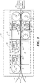
- Fig. 1 is an overall schematic of a portion of the corrugated board manufacturing process incorporating a preferred embodiment of the present invention.
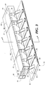
- Fig. 2 is an overall perspective view of the preferred embodiment of the Fig. 1.
- Fig. 3 is a more detailed perspective view of the preferred embodiment of Fig. 1.
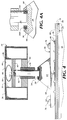
- Fig. 4 is a side sectional view as seen along line 4-4 of the preferred embodiment of Fig. 3.
- Fig. 4A is a close up view of a portion of Fig. 4.
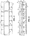
- Fig. 5 is a plan view of the preferred embodiment as shown in Fig. 3.
- Fig. 6 is a front view of the preferred embodiment as shown in Fig. 3.
- Fig. 7 is a bottom sectional view as seen along line 7-7 of the preferred embodiment of Fig. 2.
- Fig. 8 is a side view of the preferred embodiment of Fig. 7.
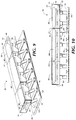
- Fig. 9 is a perspective view of a first alternative embodiment of the present invention.
- Fig. 10 is a front view of the alternative embodiment of Fig. 9.
- Fig. 11 is a perspective view of a second alternative embodiment of the present invention.
- Fig. 12 is a perspective view of a third alternative embodiment of the present invention.
- Fig. 13 is a bottom view of an alternative embodiment of Fig. 7.
- Fig. 14 is a fourth alternative embodiment of the present invention.
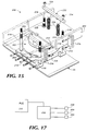
- Fig. 15 is a perspective view of a sixth embodiment of the present invention.
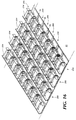
- Fig. 16 is a perspective view of a plurality of the pressure applicators set forth in Fig. 15.
- Fig. 17 is a schematic of the control system for allocating air to each of the pressure applicators set forth in Fig 16.
- Fig. 1 shows a schematic representation of corrugated board as it moves through a portion of a typical manufacturing facility.
- the corrugated board 10 comprises a liner 12 and a liner/median combination 14.
- the liner 12 and liner/median combination 14 are coated with an adhesive 16 and are placed so that the coated surfaces are in contact with one another throughout the surface areas.
- the liner 12 and liner/median combination 14 with adhesive 16 therebetween are referred throughout this description as adhering layers 18.
- the adhering layers 18 of corrugated board 10 pass through a hot plate section 20 of a double facer area 21 of the corrugated board assembly where the board 10 is subject to increased pressure and heat to quickly and effectively cause the adhering layers to bond to one another.
- the board 10 passes through the hot plate section 20
- the board passes through the cooling section 23 of the double facer area 21 where the adhering layers 18 cool and the adhesion process is complete.
- the board 10 passes on to the cutting section 25 where the board is cut, scored and formed into boxes, cases, cartons and the like.
- the present invention focuses on the application of a variable pressure in the double facer area 21 of a corrugated board manufacturing facility.
- the liner 12 and the liner/median combination 14 are joined with the adhesive 16 therebetween.
- the adhesive 16 is typically a starch based product containing water. When the water evaporates from the product, the adhesive 16 is fully dried and the layers 18 adhere to one another.
- a continuous upper belt 22 feeds the adhering layers 18 through the double facer area 21.
- the upper belt 22 is supported at opposing ends by rotating shafts 24.
- the shafts 24 are driven by electric motors (not shown) that supply the power to provide rotary motion to the shafts.
- the upper surface area 26 of the adhering layers 18 contacts the upper belt 22 as shown in Figs. 1, 2 and 4.
- the lower surface area 28 of the adhering layers 18 contacts the upper surfaces 30 of a series of steam chests 32 as shown in Fig. 1.
- a boiler (not shown) supplies steam to the steam chests.
- the upper surface of the adhering layers 18 contacts the upper belt 22 and the lower surface of the adhering layers contacts a lower belt 68.
- the lower belt 68 is also continuous and is mounted between a pair of rotating shafts 24 in a similar arrangement as that described above with regard to the upper belt 22.
- a frame 34 is located above the upper belt 22.
- the frame 34 is mounted to a fixed structure (not shown) above the upper surface 26 of the layers 18 and oriented perpendicular to the path of travel of the layers.
- the path of travel is indicated by arrow 35.
- the frame 34 is made up of a pair of parallel spaced apart members 36, as shown in Figs. 3 and 4.
- Figure 3 shows the frame 34 separated into three longitudinally spaced sections 31 by divider plates 33.
- the spaced apart members 36 of the frame 34 within each section 31 are joined along their length by a cover plate 38, and a bottom plate 42.
- a series of parallel, spaced apart loading plates 40 are located between the cover plate 38 and the bottom plate 42 of each section 31.
- the cover plate 38 and loading plate 40 are spaced apart to create a sealed cavity 44 within each section of the frame 34.
- Each cavity 44 houses an air bladder 48.
- the loading plates 40 in each section 31 are in contact with the air bladder 48.
- Each loading plate 40 slides relative to the frame 34 in a vertical direction between the opposing surfaces of the spaced apart members 36 of the frame 34 as a result of increased air introduced into the air bladder 48.
- the cover plate 38 remains stationary.
- a pressure rod 50 (also referred to as a pivot member) is secured to each loading plate 40, as best shown in Figs. 2 through 4. Each pressure rod is oriented substantially vertical and secured to the loading plate 40 by a loading plate screw 52.
- each rod 50 extends through the bottom plate 42 and is held in vertical alignment by means of a linear bearing 78.
- the inner race of the linear bearing 78 contacts the outer periphery of the rod 50.
- Each linear bearing 78 is press fit into the bottom plate 42.
- the bottom plate 42 is located substantially parallel to and below the loading plate 40.
- the bottom plate 42 is spaced sufficiently apart from the loading plate 40 to allow the loading plate to move vertically relative to the frame 34.
- the free end of the pressure rod 50 is joined to a spherical bearing 54, as shown in detail in Fig. 4A.
- the outer diameter of the free end of the rod 50 is press fit into the inner diameter of the inner race 54A of the spherical bearing 54.
- the outer race 54B of the spherical bearing 54 is joined to a pressure foot 56 by means of set screws 58.
- the pressure foot 56 shown in Fig. 4 comprises a foot frame 60 and a flat section 62 oriented substantially parallel to the path of travel of the adhering layers 18.
- the foot frame 60 includes protruding member 64 extending upwardly and centrally from the flat section 62.
- the foot frame 60 has a cylindrical recess 66 along the upper surface of the frame 60.
- the cylindrical recess is shown in detail in Fig. 4A.
- the recess 66 receives the outer race 54B of the spherical bearing 54.
- the set screws 58 are passed through the set screw holes to the foot frame 60 into matingly tapped holes 72 in the outer race 54B to secure the foot frame to the spherical bearing 54.
- the flat section 62 of the pressure foot 56 is substantially flat and oblong, as shown in Fig. 5.
- the bottom of the flat section 62 is coated with an anti-friction material 74 such as a ceramic, as shown in Figs. 4 and 6.
- anti-friction materials such as Teflon®, may be used if they can effectively adhere to the foot material which is preferably a cast metal.
- the bottom of the flat section 62 of the pressure foot 56 has a series of angled grooves 80 extending outward from the center of the bottom of the pressure foot as shown in Figs. 7 and 8.
- the upper belt 22 tends to become wet when exposed to the moist adhesive.
- the grooves 80 allow the belt to dry while maintaining pressure on the adhering layers 18.
- there are a plurality of pressure rods 50 extending from the loading plates 40.
- there are a plurality of pressure feet 56 extending from the loading plates 40 as well.
- Mechanical links 76 shown in Figs. 5 and 6, are secured between adjacent feet 56 to prevent the feet from contacting each other and to keep the sides of the feet substantially parallel to one another.
- the adhering layers 18 of corrugated board 10 contact the upper and lower belts 22 and 68 in the cooling section 23 of the double face area 21. Pressure is applied to the upper 26 and lower 28 surface areas of the adhering layers 18 by the pressure feet 56 as described above.
- the pressure feet 56 are arranged as described in detail above and contact the upper belt 22 which in turn contacts the upper surface area 26 of the adhering layers 18. Additional pressure feet 56 are invertedly mounted so that pressure is also applied to the lower surface area 28 of the adhering layers 18.
- the liner 12 and liner/median 14 combination have adhesive 16 applied therebetween and contact each other throughout their opposing surface areas.
- These adhering layers 18 are fed into the hot plate section 20 by means of the continuous upper belt 22.
- the upper belt 22 is driven by rotatable shafts 24 at each end.
- the adhering layers 18 move through the hot plate section 20, they contact the upper belt 22 on the upper surface 26 of the layers and the steam chests 32 on the lower surface 28 of the layers.
- the pressure feet 56 are located above the belt 22. The bottom of the flat section 62 of each foot 56 contacts the belt 22.
- Pressurized air is supplied to the air bladders 48 within each section 31 to a level commensurate with the degree of pressure needed to be applied to the adhering layers 18.
- the pressure within the air bladders 48 within each section 31 is increased by supplying the air bladder 48 with high pressure air from a compressed air tank (not shown).
- a compressed air tank not shown.
- the pressure in the air bladder 48 increases, the surface of the bladder 48 in contact with the loading plates 40 puts pressure on the loading plates and forces the loading plates downward.
- the downward motion of the loading plates 40 moves the pressure rods 50 downward also.
- This downward motion of the rods 50 is transferred to the pressure feet 56.
- the pressure feet 56 transfer the downward pressure throughout their flat sections 62 in contact with the upper belt 22.
- the pressure from the pressure feet 56 is ultimately transferred to the adhering layers 18.
- the spherical bearings 54 allow the pressure feet 56 to move to compensate for any deformation of the steam chests 32. This enables each pressure foot 56 to evenly apply pressure through the upper belt 22 to the adhering layers 18 below. Such evenly applied pressure ensures that the adhering layers 18 contact each other which results in successful adhesion.
- the pressure in each air bladder 48 may be different. This is designed to enable the corrugated board manufacturer to vary the pressure from the center of the board 10 to the edges, where it is typically more difficult to achieve successful adhesion.
- the layers are pulled through the cooling section 23 by the upper belt 20 and the lower belt 68.
- Pressure feet 56 in contact with both the upper belt 20 and the lower belt 68 provide the friction needed to pull the adhering layers 18 through the cooling section 23.
- the pressure feet 56 invertedly mounted and in contact with the lower belt 68 provide pressure to the lower surface area 28 of the adhering layers 18.
- the invertedly mounted pressure feet 56 allow the lower surface area 28 of the adhering layers 18, which has been previously in contact with the steam chests, to cool.
- the grooved surface of the pressure feet 56 dissipates the moisture due to the wicking action of convection currents of air in the grooves thus allowing both upper belt 20 and lower belt 68 to dry.
- the air bladder acts as a shock absorber.
- a foreign object such as a large deposit of adhesive
- the rollers are incapable of compensating for such circumstance and such an object would get stuck below the roller an rip the belt, the layers, or both.
- each foot is capable of independent movement upward to allow the object to pass under the foot without damaging the belt or the layers. If the rod and foot cannot move any further upward, the movement of the belt and layers stops if the pressure within the air bladder reaches a preselected level.
- the pressure feet 56 apply pressure to a significant portion of the upper surface area 26 of the adhering layers 18, a significant surface area of the adhering layers 18 contacts the upper surface 30 of the steam chests 32 for a longer period of time. This results in effective adhesion of the layers 18 in a shorter time period.
- the benefits of the present invention enable corrugated board manufacturers to increase production speed or decrease the number of chests needed in the hot plate section 20. An increase in production speed results in great quantity of product. A decrease in the number of steam chests 32 results in a decrease in the floor space needed for production and a decrease in the energy needed for the steam chests 32. These result in decreasing the overall manufacturing cost which enable the manufacturer to realize an increase in profit.
- each foot 56 is coated with an anti-friction material 74, such a ceramic.
- This coating allows the upper belt 22 and lower belt 68 to move under the pressure foot 56 with significantly less drag.
- a decrease in the drag of the belts prolongs belt life which saves in manufacturing costs and down time.
- a decrease in belt drag decreases the energy required to move the belts along and enables the manufacturer to increase the belt life, and thus production speed.
- the pressure feet 56 of the present invention requires no alignment adjustment once the assembly is installed.
- the pressurized air bladders 48, spherical and linear bearings keep the assembly self-aligned. This saves the manufacturer time in initial start-up as well as eliminates any need for alignment repairs or adjustments.
- a first alternative embodiment of the present invention is shown in Figs. 9 and 10.
- the first alternative embodiment focuses on the number of loading plates 40 in each frame section 31.
- the preferred embodiment includes a plurality of spaced apart, parallel loading plates 40 located between the cover plate 38 and the bottom plate 42 in each section 31.
- the first alternative embodiment shows a single loading plate 40 for each frame section 31.
- a second alternative embodiment 84 is shown in Fig. 11.
- the second alternative embodiment 84 is directed to an alternative manner of applying pressure to the adhering layers 18.
- an air bladder channel 86 is mounted proximate and parallel to the corrugated board 10.
- the air bladder 48 as described in the preferred embodiment above, rests within the air bladder channel 86.
- the air bladder channel has an open section 88, the plane of which is perpendicular to the plane of the adhering layers 18.
- a pad 89 contacts the air bladder 48 in the open section 88.
- the pad 89 is fixed to a pivot rod 90.
- the pivot rod 90 is pivotably mounted on a pivot shaft 91 to a fixed member 92 proximate to and parallel with the adhering layers 18.
- the end of the pivot rod 90 opposite from the pad 89 is rotatably mounted to the pressure foot 56 as described in detail above with regard to the preferred embodiment.
- the air bladder 48 in the second alternative embodiment 84 When the air bladder 48 in the second alternative embodiment 84 is pressurized, the air bladder forces the pad 89 in the direction indicated by arrow 94.
- the force applied to the pad 89 causes the pivot rod 90 to pivot about the pivot shaft 91 as indicated by arrow 95 and pushes the foot 56 downward, shown by arrow 97 to apply pressure to the adhering layers 18 of the board 10.
- a third alternative embodiment 96 is shown in Fig. 12.
- the third alternative embodiment 96 includes an air bladder channel 86 as described above with regard to the second alternative embodiment 84.
- the air bladder channel 86 is oriented so that the open section 88 of the air bladder channel faces away from the adhering layers 18 of the board 10.
- the air bladder 48 within the air bladder channel 86 contacts an L-shaped member 98.
- the L-shaped member 98 has a long section 100 and a short section 102.
- the L-shaped member 98 is pivotably mounted along its long section 100 by means of a pivot shaft 91, as described above, to a parallel member 92.
- the parallel member 92 is mounted with respect to the third alternative embodiment 96 in a similar fashion as discussed above with regard to the second alternative embodiment 84.
- the short section 102 is connected to the pressure foot 56 by the spherical bearing 54 described above with regard to the preferred embodiment of the present invention.
- a stop 104 is fixed above the long section 100 of the L-shaped member
- the air bladder 48 when pressurized, forces the long section 100 of the L-shaped member in contact with the air bladder 98 upward as indicated by arrow 105.
- the L-shaped member pivots as result of the upward force of the air bladder 48 as indicated by arrow 106.
- This causes the short section 102 of the L-shaped member 98 to move downward and apply pressure to the pressure foot 56 and ultimately to the belt 22 and adhering layers 18 of the board 10 as shown by arrow 107.
- the stop 104 prevents the L-shaped member 98 from pushing too far downward on the belt 22 and board 10.
- the grooves 80 are arranged at an angle to the center of the foot 56 as described in detail above.
- the grooves 80 will be parallel and spaced apart and each row of pressure feet arranged in a staggered fashion as shown in Fig. 13. This staggered arrangement allows the entire surface area of the upper belt 22 and lower belt 68 momentary exposure to the air to allow the belts to dry and to allow the heat and moisture to dissipate from them.
- a fourth alternative embodiment 110 is shown in Fig. 14.
- This alternative embodiment is similar to the preferred embodiment except for the number of air bladders 48 and divider plates 33 between frame sections 31.
- each loading plate 40 has a separate air bladder associated therewith.
- Each air bladder 48 is controlled separately thus allowing fine adjustment of the application of pressure to the pressure feet 56 across the width of the corrugated board 10. This, in part, allows for the uniform removal of moisture across the width of the corrugated board 10 to prevent the board from warping.
- a sixth embodiment of a pressure applicator 200 is set forth in Figs. 15 and 16.
- the pressure applicator 200 includes an inflatable air bladder in the form of an air brake bellows 202.
- the air brake bellows 202 is for example a Airstroke® actuator two-ply bellows, model number W01-358-7451, made by Firestone.
- the lower end of the air brake bellows 202 is attached to a rigid pressure plate 56, and the upper end 206 of the air brake bellows 202 is fixed to the lower surface of an upper bracket 204.
- the bracket 204 is mounted transversely to the double-facer conveyor belt 22, as is best shown in Fig. 16.
- the rigid pressure plate 56 is designed to contact the upper surface of the belt 22 on the double-facer machine.
- Stabilizing bars 210 extend from the front edge of the upper bracket 204 diagonally downwardly to braces 211 attached at the middle of the pressure plate 56.
- the stabilizing bars 210 are rotatably attached to the braces 211 via a series of bolts 212, 214, and attachment bars 216.
- four bolts 218 extend upward from the pressure plate 56 and are slidably received through holes 220 in the upper bracket 204.
- the stabilizing bars 210 and the bolts 218 assure that the pressure plate 56 moves up and down in a direction that is relatively normal to the bracket 204.
- Bars 222 extend transversely across the upper bracket 204 and receive the upper ends of two of the bolts 218 and are held in place by nuts 224.
- a pressure device such as a pair of springs 226, extends between the bars 222 and the top of the upper bracket 204.
- the springs 226 are received in cylinders 228 on the bars 222 and are held in place at the bottom by a suitable seating means (not shown, but known in the art). It is to be understood that any type of pressure device, including but not limited to hydraulic and pneumatic devices, may be used in place of the springs 226.
- the pressure device, or springs 226, is designed to counteract the weight of the pressure plate 56 and to bias the pressure plate into a position away from the belt 22 when no air pressure is applied to the air brake bellows 202.
- air pressure is applied to the air brake bellows 202, causing the pressure plate 56 to move downward against the force of the springs 226 and apply pressure to the conveyor belt 22.
- a number of the pressure applicators 200 are aligned transversely across the belt 22, and rows of such devices (see Fig. 16) are used to distribute pressure across the width and length of the belt in the double-facer portion of the corrugate machine.
- the amount of pressure applied by the individual pressure applicators 200 may be varied, and is supplied by an controllable air source 230 attached to the air brake bellows 202 (Fig. 17).
- the amount of air pressure delivered to each individual pressure applicator 200 is determined by a programmed logic controller 232 which controls the air source 230.
- a major advantage of the sixth embodiment is that the springs 226 cause the pressure applicator 200 to be negatively loaded thereby biasing the weight of the plate 56 off of the belt 22. Thus, if a particular pressure applicator 200 is not needed in an application forming corrugated board, air is simply not supplied to the air brake bellows 202 for that particular pressure applicator.
- the pressure required to apply zero (0) pounds of pressure to the belt 22 may be within the process controls of the logic controller 232. In this manner, the programmed logic controller 232 may infinitely adjust the pressure of the pressure plate 56 on the belt 22.
- the programmed logic controller 232 described may be a general purpose programmable controller of a type well known to those skilled in the art. Furthermore, such a controller may be programmed by a programmer of ordinary skill to accept the inputs, perform the functions, and provide the outputs required for operation of the present invention, given the description contained herein.
Landscapes
- Engineering & Computer Science (AREA)
- Mechanical Engineering (AREA)
- General Engineering & Computer Science (AREA)
- Textile Engineering (AREA)
- Life Sciences & Earth Sciences (AREA)
- Microbiology (AREA)
- Physics & Mathematics (AREA)
- Fluid Mechanics (AREA)
- Machines For Manufacturing Corrugated Board In Mechanical Paper-Making Processes (AREA)
- Paper (AREA)
- Making Paper Articles (AREA)
Applications Claiming Priority (2)
| Application Number | Priority Date | Filing Date | Title |
|---|---|---|---|
| US567948 | 1995-12-06 | ||
| US08/567,948 US5611267A (en) | 1993-09-22 | 1995-12-06 | Apparatus and method for applying variable pressure to a surface in corrugated paperboard manufacturing |
Publications (3)
| Publication Number | Publication Date |
|---|---|
| EP0778124A2 true EP0778124A2 (de) | 1997-06-11 |
| EP0778124A3 EP0778124A3 (de) | 1997-12-17 |
| EP0778124B1 EP0778124B1 (de) | 1999-10-27 |
Family
ID=24269293
Family Applications (1)
| Application Number | Title | Priority Date | Filing Date |
|---|---|---|---|
| EP96102481A Expired - Lifetime EP0778124B1 (de) | 1995-12-06 | 1996-02-19 | Vorrichtung und Verfahren zur Ausführung eines veränderbaren Drucks auf eine Fläche bei der Herstellung von Doppelwelpappen |
Country Status (9)
| Country | Link |
|---|---|
| US (1) | US5611267A (de) |
| EP (1) | EP0778124B1 (de) |
| AT (1) | ATE186012T1 (de) |
| AU (1) | AU692725B2 (de) |
| BR (1) | BR9607435A (de) |
| CA (1) | CA2212301C (de) |
| DE (1) | DE69604891D1 (de) |
| ES (1) | ES2141983T3 (de) |
| WO (1) | WO1997020685A1 (de) |
Families Citing this family (11)
| Publication number | Priority date | Publication date | Assignee | Title |
|---|---|---|---|---|
| US5526739A (en) * | 1993-09-22 | 1996-06-18 | Corrugated Gear & Services Inc. | Apparatus for applying variable pressure to a surface |
| US5732622A (en) * | 1997-01-24 | 1998-03-31 | Corrugated Gear And Services | Machine for manugacturing corrugated board |
| US5915295A (en) * | 1997-10-15 | 1999-06-29 | Corrugated Gear And Services, Inc. | Machine for manufacturing corrugated board with heat exchangers on both sides of the board |
| DE19811858A1 (de) * | 1998-03-18 | 1999-09-23 | Bhs Corr Masch & Anlagenbau | Heizvorrichtung für eine Wellpappenanlage |
| US6390963B1 (en) | 1998-11-30 | 2002-05-21 | Corrugated Gear & Services, Inc. | Corrugated board manufacturing apparatus including a preheater section with a variable heat transfer system and a hotplate section with a passive hold-down mechanisim |
| US6220328B1 (en) * | 1999-09-23 | 2001-04-24 | Textile Systems & Supply, Inc. | Lamination machine |
| ES2254339T3 (es) | 2001-10-24 | 2006-06-16 | Habasit Italiana S.P.A. | Prensa de empalme. |
| US6752074B2 (en) * | 2002-07-11 | 2004-06-22 | Corrugated Gear & Services, Inc. | Machine for manufacturing corrugated board with pressure applicator stabilizers |
| AT507384B1 (de) * | 2008-09-18 | 2011-07-15 | Westwind Verpackungen Gmbh | Verschliesseinrichtung zum verschliessen von vorzugsweise beutelförmigen verpackungseinheiten |
| JP6143645B2 (ja) * | 2013-11-01 | 2017-06-07 | 三菱重工印刷紙工機械株式会社 | 両面段ボールシート反り防止装置および方法ならびに両面段ボールシート製造装置 |
| CN110303725A (zh) * | 2018-03-27 | 2019-10-08 | 上海东冠纸业有限公司 | 一种面巾纸装饰性压花装置 |
Family Cites Families (51)
| Publication number | Priority date | Publication date | Assignee | Title |
|---|---|---|---|---|
| US633665A (en) * | 1899-01-31 | 1899-09-26 | Grace E Spaulding | Letter-copying press. |
| US697287A (en) * | 1900-10-08 | 1902-04-08 | Wesley Lincoln Spaulding | Press. |
| US905076A (en) * | 1907-11-25 | 1908-11-24 | Hinde & Dauch Paper Co | Apparatus for forming multiply material. |
| US2252585A (en) * | 1939-03-20 | 1941-08-12 | Gair Company Canada Ltd | Means for drying corrugated board |
| US2554968A (en) * | 1939-03-29 | 1951-05-29 | Robert M Thompson | Continuous pressure separating device operating in multiple stages |
| US2300982A (en) * | 1941-05-29 | 1942-11-03 | Slagboom Louis | Decating machine |
| US2394941A (en) * | 1943-07-03 | 1946-02-12 | Univis Lens Co | Molding apparatus |
| US2508216A (en) * | 1947-08-08 | 1950-05-16 | Bonds | Apparatus for the preparation of printing blocks |
| US2941573A (en) * | 1958-03-28 | 1960-06-21 | Robert T Cassady | Method of and apparatus for regulating corrugating machines |
| US3217425A (en) * | 1962-09-25 | 1965-11-16 | West Virginia Pulp & Paper Co | Corrugator |
| US3319353A (en) * | 1964-03-30 | 1967-05-16 | Niwa Machinery Company Ltd | Pressing and drying devices for corrugated board manufacturing equipment |
| US3190215A (en) * | 1964-05-11 | 1965-06-22 | Reginald C Howard | Fluid actuated press |
| US3434901A (en) * | 1965-10-23 | 1969-03-25 | West Virginia Pulp & Paper Co | Method for manufacturing corrugated board |
| US3468734A (en) * | 1966-02-07 | 1969-09-23 | S & S Corrugated Paper Mach | Method and apparatus for producing corrugated board |
| US3444029A (en) * | 1966-03-16 | 1969-05-13 | Radyne Ltd | Wood panel press |
| US3580795A (en) * | 1966-10-05 | 1971-05-25 | John E Eichenlaub | Apparatus for welding heat sealable sheet material |
| US3607523A (en) * | 1969-07-28 | 1971-09-21 | Harris Intertype Corp | Double facer heat control method and apparatus |
| DE1957270B1 (de) * | 1969-11-14 | 1971-04-22 | Eickhoff Geb | Vorrichtung zum Herstellen von Wellpappe mit doppelseitig glatter Deckbahn |
| DE2108378C3 (de) * | 1971-02-22 | 1973-10-18 | Eickhoff-Universal Wellpappenmaschinen Gmbh, 4630 Bochum | Vorrichtung zum Herstellen von Wellpappe mit doppelseitig glatter Bahn |
| US3783097A (en) * | 1972-05-30 | 1974-01-01 | Beloit Corp | Hydrodynamically loaded web press with slipper bearing shoes |
| US3829338A (en) * | 1972-06-14 | 1974-08-13 | Harris Intertype Corp | Double facer machine heat control |
| US3943025A (en) * | 1973-05-07 | 1976-03-09 | Russell George F | Laminating travelling press |
| US3981758A (en) * | 1974-11-04 | 1976-09-21 | Koppers Company, Inc. | Process control system for corrugators |
| CA1035333A (en) * | 1975-02-13 | 1978-07-25 | John J. Grevich | Band sealer for closing bags |
| GB1513564A (en) * | 1975-03-08 | 1978-06-07 | Simon Container Mach Ltd | Corrugating machinery |
| US4042446A (en) * | 1975-08-14 | 1977-08-16 | Henry Simon Limited | Corrugated board-making machinery |
| US4126508A (en) * | 1976-09-13 | 1978-11-21 | Boise Cascade Corporation | Apparatus for forming multi-flute-layer corrugated board |
| US4079617A (en) * | 1977-04-11 | 1978-03-21 | Whiting Richard B | Pneumatic press |
| US4268341A (en) * | 1978-03-15 | 1981-05-19 | S&S Corrugated Paper Machinery Co. Inc. | Zero waste order change system for a corrugator |
| US4286490A (en) * | 1978-06-03 | 1981-09-01 | Stanztechnik Gmbh R & S | Force application apparatus |
| DE2851007C3 (de) * | 1978-11-24 | 1982-02-04 | BHS-Bayerische Berg-, Hütten- und Salzwerke AG, 8000 München | Vorrichtung zur Herstellung einer wenigstens einseitig deckbelegten Wellpappe |
| US4316755A (en) * | 1979-03-20 | 1982-02-23 | S&S Corrugated Paper Machinery Co., Inc. | Adhesive metering device for corrugating processes |
| DE2935373C2 (de) * | 1979-09-01 | 1985-08-08 | Lindauer Dornier Gmbh, 8990 Lindau | Vorrichtung zur Wärmebehandlung von flachen, auf gasdurchlässigen Transportbändern aufliegenden Warenbahnen |
| FI76856C (fi) * | 1987-02-05 | 1988-12-12 | Tampella Oy Ab | Foerfarande och anordning foer torkning av en pappersbana eller liknande. |
| US4816103A (en) * | 1987-04-21 | 1989-03-28 | Ethan Ernest | Process for manufacturing corrugated plywood composites |
| JPH0246616U (de) * | 1988-09-26 | 1990-03-30 | ||
| JPH02196642A (ja) * | 1989-01-26 | 1990-08-03 | Mitsubishi Heavy Ind Ltd | コルゲートマシン |
| GB8916373D0 (en) * | 1989-07-18 | 1989-09-06 | Simon Container Mach Ltd | A heat transfer system |
| DE69015482T2 (de) * | 1989-07-18 | 1995-05-24 | Scm Container Mach Ltd | Wärmeübertragungssystem. |
| US5256240A (en) * | 1989-07-18 | 1993-10-26 | Simon Container Machinery Limited | Corrugating machine with a flexible vessel pressure applying means |
| US5324383A (en) * | 1990-05-16 | 1994-06-28 | Lin Pac, Inc. | Apparatus for forming laminated corrugated materials |
| US5160400A (en) * | 1990-05-24 | 1992-11-03 | United Container Machinery Group, Inc. | Corrugating apparatus having a liquid filled seal roll |
| US5183525A (en) * | 1990-05-24 | 1993-02-02 | United Container Machinery Group, Inc. | Heater for a double facing corrugating machine |
| CH684688A5 (fr) * | 1990-11-14 | 1994-11-30 | Bobst Sa | Dispositif d'assemblage pour élément en bande composé de couches superposées et encollées pour une machine de production de carton ondulé. |
| JP2592183B2 (ja) * | 1990-12-25 | 1997-03-19 | 三菱重工業株式会社 | 片面段ボール製造機 |
| DE4108936A1 (de) * | 1991-03-19 | 1992-09-24 | Kannegiesser H Gmbh Co | Vorrichtung zum verkleben textiler flaechengebilde |
| DE69301776T2 (de) * | 1992-06-19 | 1996-08-08 | Peters W Maschf | Einseitige Wellpappen-Herstellungsmaschine |
| US5337656A (en) * | 1993-05-06 | 1994-08-16 | Kcs Industries Inc. | Oil filter crushing apparatus having air bag actuator |
| US5456783A (en) * | 1993-05-06 | 1995-10-10 | Interfic Developments Incorporated | Apparatus and method for enhancing heating uniformity for setting adhesive in corrugated paperboard manufacturing |
| US5466329A (en) * | 1994-06-03 | 1995-11-14 | Marquip, Inc. | Adjustable ballast system for the holddown belt in a double facer |
| US5501762A (en) * | 1994-06-07 | 1996-03-26 | Marquip, Inc. | Hot plate for corrugated paperboard double facer |
-
1995
- 1995-12-06 US US08/567,948 patent/US5611267A/en not_active Expired - Lifetime
-
1996
- 1996-02-19 ES ES96102481T patent/ES2141983T3/es not_active Expired - Lifetime
- 1996-02-19 DE DE69604891T patent/DE69604891D1/de not_active Expired - Lifetime
- 1996-02-19 EP EP96102481A patent/EP0778124B1/de not_active Expired - Lifetime
- 1996-02-19 AT AT96102481T patent/ATE186012T1/de not_active IP Right Cessation
- 1996-12-06 WO PCT/US1996/019939 patent/WO1997020685A1/en not_active Ceased
- 1996-12-06 BR BR9607435A patent/BR9607435A/pt not_active IP Right Cessation
- 1996-12-06 CA CA002212301A patent/CA2212301C/en not_active Expired - Lifetime
- 1996-12-06 AU AU11520/97A patent/AU692725B2/en not_active Ceased
Also Published As
| Publication number | Publication date |
|---|---|
| WO1997020685A1 (en) | 1997-06-12 |
| AU692725B2 (en) | 1998-06-11 |
| BR9607435A (pt) | 1998-11-17 |
| DE69604891D1 (de) | 1999-12-02 |
| ATE186012T1 (de) | 1999-11-15 |
| CA2212301A1 (en) | 1997-06-12 |
| EP0778124B1 (de) | 1999-10-27 |
| ES2141983T3 (es) | 2000-04-01 |
| AU1152097A (en) | 1997-06-27 |
| US5611267A (en) | 1997-03-18 |
| CA2212301C (en) | 2001-01-16 |
| EP0778124A3 (de) | 1997-12-17 |
| MX9705788A (es) | 1997-10-31 |
Similar Documents
| Publication | Publication Date | Title |
|---|---|---|
| US5526739A (en) | Apparatus for applying variable pressure to a surface | |
| US5611267A (en) | Apparatus and method for applying variable pressure to a surface in corrugated paperboard manufacturing | |
| US5456783A (en) | Apparatus and method for enhancing heating uniformity for setting adhesive in corrugated paperboard manufacturing | |
| EP0294992B1 (de) | Schabervorrichtung | |
| US6110095A (en) | Apparatus for heating corrugated paperboard | |
| US5320036A (en) | Continuously operating material press | |
| US5993587A (en) | Double facer with threading means | |
| EP1491326B1 (de) | Vorrichtung zum Verbinden von Kartonbögen zur Herstellung von Wellpappe | |
| US5527422A (en) | Machine for continuous manufacture of chipboards, fibreboards or similar products | |
| US5248362A (en) | Method for applying glue to the flute tips of a single-faced corrugated paperboard sheet | |
| US6143112A (en) | Method and apparatus for producing single face corrugated web | |
| US5732622A (en) | Machine for manugacturing corrugated board | |
| US5129980A (en) | Apparatus for applying glue to the flute tips of a single-faced corrugated paperboard sheet | |
| US5902502A (en) | Corrugated paperboard manufacturing apparatus and related methods | |
| NL8502356A (nl) | Lijmopbrenginrichting voor van een buitenzijde voorziene gegolfde baan. | |
| MXPA97005788A (en) | Apparatus and method for applying a variable pressure to a surface in the manufacture of cartoncorug | |
| US5910230A (en) | Stuck sheet material manufacturing system equipped with pressure device | |
| US5439544A (en) | No-crush roll system and method in a double backer | |
| CN222389173U (zh) | 一种纸板整平装置 | |
| WO1999024249A1 (en) | Corrugated paperboard manufacturing apparatus and method for enhancing heat transfer to an advancing corrugated paperboard sheet | |
| JP2002120308A (ja) | ダブルフェーサの荷重装置 | |
| JPH10305499A (ja) | ダブルフェーサ | |
| JP2002307581A (ja) | ダブルフェーサの加圧装置 |
Legal Events
| Date | Code | Title | Description |
|---|---|---|---|
| PUAI | Public reference made under article 153(3) epc to a published international application that has entered the european phase |
Free format text: ORIGINAL CODE: 0009012 |
|
| AK | Designated contracting states |
Kind code of ref document: A2 Designated state(s): AT BE CH DE DK ES FR GB GR IE IT LI LU MC NL PT SE |
|
| PUAL | Search report despatched |
Free format text: ORIGINAL CODE: 0009013 |
|
| 17P | Request for examination filed |
Effective date: 19971001 |
|
| AK | Designated contracting states |
Kind code of ref document: A3 Designated state(s): AT BE CH DE DK ES FR GB GR IE IT LI LU MC NL PT SE |
|
| 17Q | First examination report despatched |
Effective date: 19980414 |
|
| GRAG | Despatch of communication of intention to grant |
Free format text: ORIGINAL CODE: EPIDOS AGRA |
|
| GRAG | Despatch of communication of intention to grant |
Free format text: ORIGINAL CODE: EPIDOS AGRA |
|
| GRAG | Despatch of communication of intention to grant |
Free format text: ORIGINAL CODE: EPIDOS AGRA |
|
| GRAH | Despatch of communication of intention to grant a patent |
Free format text: ORIGINAL CODE: EPIDOS IGRA |
|
| GRAH | Despatch of communication of intention to grant a patent |
Free format text: ORIGINAL CODE: EPIDOS IGRA |
|
| GRAA | (expected) grant |
Free format text: ORIGINAL CODE: 0009210 |
|
| AK | Designated contracting states |
Kind code of ref document: B1 Designated state(s): AT BE CH DE DK ES FR GB GR IE IT LI LU MC NL PT SE |
|
| PG25 | Lapsed in a contracting state [announced via postgrant information from national office to epo] |
Ref country code: NL Free format text: LAPSE BECAUSE OF FAILURE TO SUBMIT A TRANSLATION OF THE DESCRIPTION OR TO PAY THE FEE WITHIN THE PRESCRIBED TIME-LIMIT Effective date: 19991027 Ref country code: LI Free format text: LAPSE BECAUSE OF FAILURE TO SUBMIT A TRANSLATION OF THE DESCRIPTION OR TO PAY THE FEE WITHIN THE PRESCRIBED TIME-LIMIT Effective date: 19991027 Ref country code: GR Free format text: LAPSE BECAUSE OF NON-PAYMENT OF DUE FEES Effective date: 19991027 Ref country code: FR Free format text: LAPSE BECAUSE OF FAILURE TO SUBMIT A TRANSLATION OF THE DESCRIPTION OR TO PAY THE FEE WITHIN THE PRESCRIBED TIME-LIMIT Effective date: 19991027 Ref country code: CH Free format text: LAPSE BECAUSE OF FAILURE TO SUBMIT A TRANSLATION OF THE DESCRIPTION OR TO PAY THE FEE WITHIN THE PRESCRIBED TIME-LIMIT Effective date: 19991027 Ref country code: BE Free format text: LAPSE BECAUSE OF FAILURE TO SUBMIT A TRANSLATION OF THE DESCRIPTION OR TO PAY THE FEE WITHIN THE PRESCRIBED TIME-LIMIT Effective date: 19991027 Ref country code: AT Free format text: LAPSE BECAUSE OF FAILURE TO SUBMIT A TRANSLATION OF THE DESCRIPTION OR TO PAY THE FEE WITHIN THE PRESCRIBED TIME-LIMIT Effective date: 19991027 |
|
| REF | Corresponds to: |
Ref document number: 186012 Country of ref document: AT Date of ref document: 19991115 Kind code of ref document: T |
|
| REG | Reference to a national code |
Ref country code: CH Ref legal event code: EP |
|
| REF | Corresponds to: |
Ref document number: 69604891 Country of ref document: DE Date of ref document: 19991202 |
|
| ITF | It: translation for a ep patent filed | ||
| REG | Reference to a national code |
Ref country code: IE Ref legal event code: FG4D |
|
| PG25 | Lapsed in a contracting state [announced via postgrant information from national office to epo] |
Ref country code: PT Free format text: LAPSE BECAUSE OF FAILURE TO SUBMIT A TRANSLATION OF THE DESCRIPTION OR TO PAY THE FEE WITHIN THE PRESCRIBED TIME-LIMIT Effective date: 20000127 Ref country code: DK Free format text: LAPSE BECAUSE OF FAILURE TO SUBMIT A TRANSLATION OF THE DESCRIPTION OR TO PAY THE FEE WITHIN THE PRESCRIBED TIME-LIMIT Effective date: 20000127 |
|
| PG25 | Lapsed in a contracting state [announced via postgrant information from national office to epo] |
Ref country code: DE Free format text: LAPSE BECAUSE OF FAILURE TO SUBMIT A TRANSLATION OF THE DESCRIPTION OR TO PAY THE FEE WITHIN THE PRESCRIBED TIME-LIMIT Effective date: 20000128 |
|
| EN | Fr: translation not filed | ||
| REG | Reference to a national code |
Ref country code: ES Ref legal event code: FG2A Ref document number: 2141983 Country of ref document: ES Kind code of ref document: T3 |
|
| NLV1 | Nl: lapsed or annulled due to failure to fulfill the requirements of art. 29p and 29m of the patents act | ||
| PGFP | Annual fee paid to national office [announced via postgrant information from national office to epo] |
Ref country code: GB Payment date: 20000414 Year of fee payment: 5 |
|
| PGFP | Annual fee paid to national office [announced via postgrant information from national office to epo] |
Ref country code: LU Payment date: 20000419 Year of fee payment: 5 |
|
| PGFP | Annual fee paid to national office [announced via postgrant information from national office to epo] |
Ref country code: SE Payment date: 20000427 Year of fee payment: 5 Ref country code: DK Payment date: 20000427 Year of fee payment: 5 |
|
| PGFP | Annual fee paid to national office [announced via postgrant information from national office to epo] |
Ref country code: IE Payment date: 20000428 Year of fee payment: 5 |
|
| REG | Reference to a national code |
Ref country code: CH Ref legal event code: PL |
|
| PGFP | Annual fee paid to national office [announced via postgrant information from national office to epo] |
Ref country code: BE Payment date: 20000518 Year of fee payment: 5 |
|
| PLBE | No opposition filed within time limit |
Free format text: ORIGINAL CODE: 0009261 |
|
| STAA | Information on the status of an ep patent application or granted ep patent |
Free format text: STATUS: NO OPPOSITION FILED WITHIN TIME LIMIT |
|
| PGFP | Annual fee paid to national office [announced via postgrant information from national office to epo] |
Ref country code: MC Payment date: 20000830 Year of fee payment: 5 |
|
| 26N | No opposition filed | ||
| PG25 | Lapsed in a contracting state [announced via postgrant information from national office to epo] |
Ref country code: LU Free format text: LAPSE BECAUSE OF NON-PAYMENT OF DUE FEES Effective date: 20010219 Ref country code: IE Free format text: LAPSE BECAUSE OF NON-PAYMENT OF DUE FEES Effective date: 20010219 Ref country code: GB Free format text: LAPSE BECAUSE OF NON-PAYMENT OF DUE FEES Effective date: 20010219 |
|
| PG25 | Lapsed in a contracting state [announced via postgrant information from national office to epo] |
Ref country code: SE Free format text: LAPSE BECAUSE OF NON-PAYMENT OF DUE FEES Effective date: 20010228 Ref country code: MC Free format text: LAPSE BECAUSE OF NON-PAYMENT OF DUE FEES Effective date: 20010228 |
|
| GBPC | Gb: european patent ceased through non-payment of renewal fee |
Effective date: 20010219 |
|
| REG | Reference to a national code |
Ref country code: IE Ref legal event code: MM4A |
|
| PGFP | Annual fee paid to national office [announced via postgrant information from national office to epo] |
Ref country code: IT Payment date: 20060228 Year of fee payment: 11 |
|
| PGFP | Annual fee paid to national office [announced via postgrant information from national office to epo] |
Ref country code: ES Payment date: 20080226 Year of fee payment: 13 |
|
| PG25 | Lapsed in a contracting state [announced via postgrant information from national office to epo] |
Ref country code: IT Free format text: LAPSE BECAUSE OF NON-PAYMENT OF DUE FEES Effective date: 20070219 |
|
| REG | Reference to a national code |
Ref country code: ES Ref legal event code: FD2A Effective date: 20090220 |
|
| PG25 | Lapsed in a contracting state [announced via postgrant information from national office to epo] |
Ref country code: ES Free format text: LAPSE BECAUSE OF NON-PAYMENT OF DUE FEES Effective date: 20090220 |