EP0778406A2 - Dispositif et méthode par la détection d'anomalies d'un détecteur de débit d'air - Google Patents
Dispositif et méthode par la détection d'anomalies d'un détecteur de débit d'air Download PDFInfo
- Publication number
- EP0778406A2 EP0778406A2 EP96119463A EP96119463A EP0778406A2 EP 0778406 A2 EP0778406 A2 EP 0778406A2 EP 96119463 A EP96119463 A EP 96119463A EP 96119463 A EP96119463 A EP 96119463A EP 0778406 A2 EP0778406 A2 EP 0778406A2
- Authority
- EP
- European Patent Office
- Prior art keywords
- air
- air flow
- flow meter
- range
- opening size
- Prior art date
- Legal status (The legal status is an assumption and is not a legal conclusion. Google has not performed a legal analysis and makes no representation as to the accuracy of the status listed.)
- Granted
Links
- 230000005856 abnormality Effects 0.000 title claims abstract description 78
- 238000000034 method Methods 0.000 title claims description 9
- 230000005611 electricity Effects 0.000 claims description 3
- 239000003570 air Substances 0.000 description 146
- 238000001514 detection method Methods 0.000 description 23
- 239000000446 fuel Substances 0.000 description 13
- MWUXSHHQAYIFBG-UHFFFAOYSA-N Nitric oxide Chemical compound O=[N] MWUXSHHQAYIFBG-UHFFFAOYSA-N 0.000 description 12
- 238000002485 combustion reaction Methods 0.000 description 11
- 239000002826 coolant Substances 0.000 description 10
- QVGXLLKOCUKJST-UHFFFAOYSA-N atomic oxygen Chemical compound [O] QVGXLLKOCUKJST-UHFFFAOYSA-N 0.000 description 6
- 239000001301 oxygen Substances 0.000 description 6
- 229910052760 oxygen Inorganic materials 0.000 description 6
- 239000007789 gas Substances 0.000 description 5
- 238000002347 injection Methods 0.000 description 5
- 239000007924 injection Substances 0.000 description 5
- UGFAIRIUMAVXCW-UHFFFAOYSA-N Carbon monoxide Chemical compound [O+]#[C-] UGFAIRIUMAVXCW-UHFFFAOYSA-N 0.000 description 4
- 229910002091 carbon monoxide Inorganic materials 0.000 description 4
- 230000004075 alteration Effects 0.000 description 3
- 230000003197 catalytic effect Effects 0.000 description 3
- 230000001419 dependent effect Effects 0.000 description 3
- 230000002159 abnormal effect Effects 0.000 description 2
- 238000010586 diagram Methods 0.000 description 2
- 239000012080 ambient air Substances 0.000 description 1
- 239000003054 catalyst Substances 0.000 description 1
- 230000002153 concerted effect Effects 0.000 description 1
- 238000012790 confirmation Methods 0.000 description 1
- 230000001934 delay Effects 0.000 description 1
- 230000006866 deterioration Effects 0.000 description 1
- 230000000694 effects Effects 0.000 description 1
- 239000000203 mixture Substances 0.000 description 1
- BASFCYQUMIYNBI-UHFFFAOYSA-N platinum Chemical compound [Pt] BASFCYQUMIYNBI-UHFFFAOYSA-N 0.000 description 1
- 230000010349 pulsation Effects 0.000 description 1
- 230000035945 sensitivity Effects 0.000 description 1
- 238000011144 upstream manufacturing Methods 0.000 description 1
Images



Classifications
-
- F—MECHANICAL ENGINEERING; LIGHTING; HEATING; WEAPONS; BLASTING
- F02—COMBUSTION ENGINES; HOT-GAS OR COMBUSTION-PRODUCT ENGINE PLANTS
- F02D—CONTROLLING COMBUSTION ENGINES
- F02D41/00—Electrical control of supply of combustible mixture or its constituents
- F02D41/22—Safety or indicating devices for abnormal conditions
- F02D41/222—Safety or indicating devices for abnormal conditions relating to the failure of sensors or parameter detection devices
-
- F—MECHANICAL ENGINEERING; LIGHTING; HEATING; WEAPONS; BLASTING
- F02—COMBUSTION ENGINES; HOT-GAS OR COMBUSTION-PRODUCT ENGINE PLANTS
- F02D—CONTROLLING COMBUSTION ENGINES
- F02D41/00—Electrical control of supply of combustible mixture or its constituents
- F02D41/02—Circuit arrangements for generating control signals
- F02D41/18—Circuit arrangements for generating control signals by measuring intake air flow
-
- Y—GENERAL TAGGING OF NEW TECHNOLOGICAL DEVELOPMENTS; GENERAL TAGGING OF CROSS-SECTIONAL TECHNOLOGIES SPANNING OVER SEVERAL SECTIONS OF THE IPC; TECHNICAL SUBJECTS COVERED BY FORMER USPC CROSS-REFERENCE ART COLLECTIONS [XRACs] AND DIGESTS
- Y02—TECHNOLOGIES OR APPLICATIONS FOR MITIGATION OR ADAPTATION AGAINST CLIMATE CHANGE
- Y02T—CLIMATE CHANGE MITIGATION TECHNOLOGIES RELATED TO TRANSPORTATION
- Y02T10/00—Road transport of goods or passengers
- Y02T10/10—Internal combustion engine [ICE] based vehicles
- Y02T10/40—Engine management systems
Definitions
- the present invention relates to an apparatus and method for detecting abnormality of an air flow meter, which is located in an engine's intake passage to detect the air flow therein. More particularly, the present invention pertains to an apparatus and method for detecting abnormalities of a hot wire air flow meter.
- the flow rate of air drawn through an intake passage toward a combustion chamber is an important parameter.
- the air flow rate is used to compute a target value of the amount of fuel that is to be supplied to the engine.
- the intake passage is provided with an air flow meter.
- air flow meters There are several types of air flow meters. For example, there are movable vane meters, Karman vortex meters, and hot wire meters.
- a hot wire air flow meter includes a hot wire that is arranged in the intake passage.
- the hot wire is heated when electricity flows therethrough.
- the temperature of the hot wire is altered by the flow rate of the air passing through the intake passage.
- the voltage of the hot wire is altered.
- the voltage value and its altering rate corresponds to the air flow rate and its altering rate.
- the engine is controlled in accordance with the air flow rate detected by the air flow meter. Therefore, when the air flow rate is not detected due to abnormalities, such as short circuits or disconnection of the wire, the controlling of the engine becomes inappropriate.
- the concentration of nitrogen oxide (NOx), carbon monoxide (CO), and other components contained in the exhaust gas from the engine may be altered to an undesirable level. Accordingly, it is necessary to detect abnormalities of the hot wire air flow meter for optimum control of the engine.
- Japanese Unexamined Patent Publication No. 6-346778 describes an example of a detecting apparatus (first prior art apparatus) that detects abnormalities of a hot wire air flow meter such as short circuits and disconnections.
- the detecting apparatus detects abnormalities that disable detection of the air flow rate with the air flow meter. Abnormalities are confirmed by the apparatus when the voltage output of the meter is continuously higher than a reference value over a predetermined time length.
- a detecting apparatus that detects not only the abnormalities that cause malfunctioning of the air flow meter but also other abnormalities that obstruct inaccurate reading of the meter.
- the characteristics of this detecting apparatus are shown in Fig. 8.
- the graph shows the relationship between the throttle opening TA, which is related with the air flow rate of the engine, and the output voltage VG of the air flow meter.
- the two areas that are marked by slanted lines indicate ranges in which the air flow meter would not register unless an abnormality of the air flow meter exists. In other words, the slanted lines show ranges that are out of the acceptable registering range of the air flow meter.
- Parameters including the engine speed, the throttle opening, and the coolant temperature are employed to determine the abnormal registering range.
- line L11 indicates the optimum relationship between the throttle opening TA and the output voltage VG.
- a range in which the air flow rate detected by the air flow meter would be normal is indicated between the upper and lower bounding lines L12. Accordingly, when the air flow meter output voltage VG is in the range between the upper and lower bounding lines L12, the air flow meter is functioning normally and the value detected by the meter (output voltage VG) is normal.
- the detecting apparatus detects abnormalities related to the accuracy of the air flow meter when the output voltage VG of the meter is out of the acceptable registering range.
- the first prior art apparatus detects abnormalities that disable detection of the air flow rate with the air flow meter. An abnormality of the air flow meter is confirmed when the output voltage of the meter continuously exceeds the reference value for a predetermined time length. Abnormalities that result in inaccurate reading of the air flow meter are not detected by this apparatus.
- abnormalities related to the accuracy of the air flow meter may not be detected even when the output voltage VG is outside of the normal range. Furthermore, during a single trip starting from when the engine is started to when the engine is stopped, the conditions, or parameters required to define the unacceptable range may not be satisfied. In such cases, abnormalities are not detected each time the engine is started. This hinders the location of abnormalities at an early stage and delays replacement or repairing of the air flow meter. Consequently, the imbalance of the fuel and air supplied to the engine may cause inappropriate concentration of components such as NOx and CO in the exhaust gas.
- an improved apparatus for detecting an abnormality of an air flow meter is provided.
- the flow meter is arranged in an air intake passage of an engine to detect an actual flow rate of air flowing through the air intake passage.
- the air intake passage has a throttle valve with a variable opening size to control the actual rate of the air flowing in the air intake passage.
- the throttle valve adjusts the actual flow rate of the air according to an engine speed when the opening size is in a first range.
- the throttle valve adjusts the actual flow rate regardless of the engine speed when the opening size is in a second range.
- the apparatus is characterized by detecting means for detecting one of the opening size of the throttle valve and the engine speed and computing means for computing a target rate of the air flowing in the air intake passage based on one of the detected opening size and the detected engine speed.
- the computing means is arranged to compute a marginal range for allowing a deviation of the actual rate of the air flow from the target rate.
- the apparatus is further characterized by determining means for determining the abnormality of the air flow meter when the opening size of the throttle valve is in the second range and the actual rate of the air is out of the marginal range.
- Fig. 1 shows a gasoline engine system that employs an abnormality detecting apparatus of an air flow meter according to the first embodiment of the present invention.
- the system includes an engine 10, an intake passage 20, and an exhaust passage 30. Air is drawn into the engine 10 through the exhaust passage 20.
- the intake passage 20 includes a surge tank 23 and an intake manifold 13. Exhaust gas produced in the engine 10 is discharged therefrom through the exhaust passage 30.
- the exhaust passage 30 includes an exhaust manifold 31 and a catalytic converter 32.
- the engine 10 has a cylinder block 11.
- a plurality of combustion chambers 12 are defined in the cylinder block 11.
- An intake manifold 13, to which each combustion chamber 12 is connected, is coupled to the cylinder block 11.
- a coolant temperature sensor 41 is provided in the cylinder block 11 to detect the temperature THW of the coolant flowing therethrough.
- An air cleaner 21 is provided near the inlet of the intake passage 20.
- An intake air temperature sensor 42 is provided downstream of the air cleaner 21 in the intake passage 20. The temperature sensor 42 detects the temperature of the ambient air drawn into the intake passage 20, or the air intake temperature THA.
- a hot wire air flow meter 43 is provided downstream of the temperature sensor 42 to detect the air flow rate, or the volume of air flowing through the intake passage 20.
- the air flow meter 43 is provided with a platinum wire 43a, which has a high temperature coefficient of resistance and which serves as a detecting portion.
- the wire 43a is exposed to the air flowing through the intake passage 20.
- the wire 43a is heated when electricity flows therethrough.
- the temperature of the wire 43a is altered by the flow rate and the velocity of the air drawn through the intake passage 20. To maintain the temperature of the wire 43a at a constant value, the electric current flow rate of the wire 43a is varied.
- the flow rate of the current and its altering rate correspond to the air flow rate and its altering rate.
- the current flow rate of the wire 43a is adjusted to maintain the temperature of the wire 43a at a constant value.
- the electric current required for the adjustment is used to produce a proportional voltage VG from the air flow meter 43.
- An electronic control unit (ECU) 50 controls the engine 10 and detects abnormality of the air flow meter 43.
- the ECU 50 computes the actual air flow rate based on the voltage output VG of the air flow meter 43.
- a throttle valve 22 is provided downstream of the air flow meter 43 in the intake passage 20.
- the throttle valve 22 is opened and closed in cooperation with the movement of an accelerator pedal (not shown).
- the cooperation of the throttle valve 22 and the accelerator pedal adjusts the amount of air drawn into the combustion chambers 12.
- a throttle sensor 44 is arranged near the throttle valve 22. The throttle sensor 44 detects the opening of the throttle valve 22, or the throttle opening TA.
- the surge tank 23 suppresses pulsation of the air flowing through the intake passage 20.
- An injector 14 is provided for each combustion chamber 12 in the intake manifold 13. Each injector 14 injects fuel toward a port of the associated combustion chamber 12 when receiving an injection signal from the ECU 50. The fuel injected by each injector 14 is mixed with air and drawn into the combustion chamber 12.
- a spark plug 15 is provided for each combustion chamber 12 in the engine 10. Each spark plug 15 ignites the air-fuel mixture in the associated combustion chamber 12.
- the spark plugs 15 are connected to a distributor 16 by plug cords (not shown).
- An ignitor 17 is connected to the distributor 16. The ignitor 17 generates high voltage when receiving an ignition signal from the ECU 50. The high voltage output from the ignitor 17 is distributed to each spark plug 15 by the distributor 16 in accordance with the alteration of the crankshaft angle.
- a rotor (not shown) that rotates in cooperation with the engine 10 is incorporated in the distributor 16.
- An engine speed sensor 45 is arranged in the distributor 16 to detect the engine speed NE based on the rotation of the rotor.
- a pulse signal is output from the speed sensor 45 each time the crankshaft angle is altered, for example, by ten degrees.
- a cylinder distinguishing sensor 46 is provided in the distributor 16.
- the sensor 46 detects the alteration of the crankshaft angle in the engine 10 in accordance with the rotation of the rotor at a predetermined rate.
- a reference position signal is output from the sensor 46 each time the crankshaft angle is altered by 720 degrees.
- the exhaust manifold 31 is coupled to the cylinder block 11.
- the catalytic converter 32 provided in the exhaust passage 30 incorporates a three-way catalyst.
- An oxygen sensor 47 is arranged in the upstream vicinity of the catalytic converter 32. The oxygen sensor 47 detects the concentration of the oxygen contained in the exhaust gas. The oxygen concentration detected by the oxygen sensor 47 is referred to when feedback controlling the air-fuel ratio in the engine 10.
- a warning lamp 48 which warns the driver of abnormalities related with the air flow meter 43, is arranged on an instrument panel (not shown) provided in front of the driver's seat.
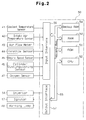
- the ECU 50 includes a central processing unit (CPU) 52, a read-only memory (ROM) 51, a random access memory (RAM) 53, and a backup RAM 54.
- the ECU 50 is constituted by a circuit in which the ROM 51, CPU 52, RAM 53, and backup RAM 54 are connected to an input interface 56 and an output interface 57 by a two-way bus 55. Things such as an abnormality detection processing program, functional data, and control programs are stored in the ROM 51.
- the abnormality detection processing program is applied to detect abnormalities of the air flow meter 43.
- the functional data is used to compute a target intake air flow rate from the throttle opening TA.
- the control programs include programs that are executed to control fuel injection such as air-fuel ratio feedback control.
- the CPU 52 executes steps based on the control programs stored in the ROM 51.
- the RAM 53 temporarily stores the data computed by the CPU 52 and the data sent from various sensors.
- the backup RAM 64 stores data that require storing when the engine 10 is stopped.
- the coolant temperature sensor 41, the intake air temperature sensor 42, the air flow meter 43, the throttle sensor 44, the engine speed sensor 45, the cylinder distinguishing sensor 46, and the oxygen sensor 47 are connected to the input interface 56.
- Analog signals sent to the input interface 56 from the sensors 41-47 are concerted into digital signals by an analog to digital (A/D) converter (not shown).
- External circuits which include the injectors 14, the ignitor 17, and the warning lamp 48, are connected to the output interface 57.
- the external circuits are controlled by the CPU 52 based on data computed through the control programs.
- Fuel injection control is performed by computing the amount of fuel injection based on the values detected by the sensors 41-47 and in correspondence with the running state of the engine 10. Fuel is injected in accordance with the computed results.
- the fuel injection control is executed by the CPU 52.
- step 100 the CPU 52 judges whether the coolant temperature THW detected by the coolant sensor 41 is 80 degrees Celsius or higher. If the coolant temperature THW is lower than 80 degrees Celsius, the engine 10 is in a cool state and not yet warmed up. Erroneous detection may occur if the abnormality detection of the air flow meter 43 is carried out when the engine 10 is cool. Thus, detection is prohibited when the engine 10 is in a cool state. Accordingly, the CPU 52 waits until the coolant temperature THW becomes 80 degrees Celsius or higher before proceeding to the subsequent step. If the coolant temperature THW is equal to or higher than 80 degrees Celsius, the CPU 52 proceeds to step 200.
- the CPU 52 judges whether the engine 10 is being started based on the signals sent from the engine speed sensor 45.
- Starting control is carried out when the engine 10 is started.
- the starting control is executed only when the engine 10 is being started and not when the engine 10 is running. Erroneous detection may take place if the abnormality detection of the air flow meter 43 is carried out during execution of the starting control. Thus, detection is prohibited when the engine 10 is being started. Accordingly, the CPU 52 waits until the starting control is completed before proceeding to the subsequent step.
- the CPU 52 proceeds to step 300.
- the throttle opening TA detected by the throttle sensor 44 and the output voltage VG of the air flow meter 43 are input in the CPU 52.
- the CPU 52 then computes the target intake air flow rate from the value of the throttle opening TA with reference to the functional data stored in the ROM 52.
- the CPU 52 judges whether the input value of the throttle opening TA is equal to or lower than a reference value ⁇ . If the value of the throttle opening TA is greater than the reference value ⁇ , the CPU 52 returns to step 300. If the throttle opening TA is equal to or lower than the reference value ⁇ , the CPU 52 proceeds to step 500.
- the graph of Fig. 4 illustrates three-dimensional, functional data (three-dimensional map), the parameters of which are the engine speed NE, the throttle opening TA, and the output voltage VG.
- the vertical axis indicates the throttle opening TA(%) while the lateral axis indicates the engine speed NE(rpm).
- Each curve represents the output voltage VG of the air flow meter 43.
- the graph of Fig. 5 shows the relationship between the throttle opening TA and the output voltage VG with respect to an arbitrary value of the engine speed NE in the three-dimensional map of Fig. 4.
- the vertical axis indicates the output voltage VG while the lateral axis indicates the throttle opening TA(%).
- the reference value ⁇ is set at a relatively low value of the throttle opening TA.
- the output voltage VG is mainly affected by the throttle opening TA.
- the influence of the engine speed NE is rather small within this range.
- the value of the throttle opening TA is small, a wide area of the intake passage 20 is closed.
- the volume of air that flows into each combustion chamber 12 is constant even when high engine speeds NE increase the velocity of the air drawn into the combustion chambers 12.
- the flow rate of the air passing through the throttle valve 22 is a determining factor that influences the velocity of the air flowing through the entire intake passage 20.
- a wide area of the intake passage 20 is opened when the value of the throttle opening TA is large. This causes the velocity of the air flowing through the intake passage 20 to be dependent on the engine speed NE. Accordingly, the air flow rate detected by the air flow meter 43 is varied when the engine speed NE is altered.
- the output voltage VG of the air flow meter 43 is proportional to the throttle opening TA when the throttle opening TA is relatively small. Accordingly, when the throttle opening TA is relatively small, detection of abnormalities of the air flow meter 43 may be carried out by using only the parameter of the throttle opening TA.
- the throttle opening TA By using the throttle opening TA in addition to the parameter of the output voltage, abnormalities of the air flow meter 43 including those that cause inaccurate readings may be detected easily.
- the value of the throttle opening TA becomes small for at least the time when the engine 10 is started. This enables confirmation of abnormalities each time the engine 10 is started.
- step 500 the CPU 52 judges whether the output voltage VG is out of a predetermined normal range. To perform the judgement, the CPU 52 computes the absolute value of the difference between the target intake air flow rate computed in Fig. 300 and the actually detected output voltage VG. The CPU 52 judges whether the absolute value is equal to or lower than a predetermined value to judge whether the output voltage VG is out of the normal range.
- the functional data used during the judgement is shown in the graph of Fig. 6.
- the conditions that are to be satisfied for detection of abnormalities are shown in the graph.
- the vertical axis indicates the output voltage VG of the air flow meter 43 while the lateral axis shows the throttle opening TA.
- Line L1 is obtained by plotting the target intake air flow rate computed in step 300.
- the optimum relationship between the throttle opening TA and the output voltage VG is indicated by line L1.
- the two upper and lower bounding lines L2 define the range in which the air flow rate detected by the air flow meter 43 is in a normal state. Accordingly, when the output voltage VG of the air flow meter 43 is in the range defined between the upper and lower bounding lines L2, the meter 43 is functioning normally.
- the absolute value of the difference between the line L1 and each bounding line L2 corresponds to the predetermined value used in step 500.
- the areas marked by slanted lines indicate a range of detection by the air flow meter 43 that is out of the normal range.
- the upper and lower broken lines L3 in the graph of Fig. 6 indicate threshold values at which the stalling of the engine 10 begins.
- the abnormality detecting apparatus detects abnormalities before the engine 10 stalls. Accordingly, in addition to abnormalities that prevent detection with the air flow meter 43, abnormalities that cause inaccurate reading of the meter 43 may also be detected.
- step 500 when the output voltage VG of the air flow meter 43 and the corresponding throttle opening TA is out of the normal range, the CPU 52 proceeds to step 600.
- step 600 the CPU 52 stores an out of range code in the backup RAM 54 and lights the warning lamp 48 provided on the instrumental panel. The CPU 52 then returns the processing to the main routine (not shown). If the output voltage VG of the air flow meter 43 and the corresponding throttle opening TA is within the predetermined range, the CPU 52 directly returns to the main routine.
- the throttle opening TA is detected as the only parameter related with the output voltage VG of the air flow meter 43.
- the output voltage VG of the air flow meter 43 is detected when the throttle opening TA is within a range in which the influences of alteration in the engine speed NE is small.
- the detected output voltage VG is used to detect abnormalities of the air flow meter 43.
- abnormalities of the air flow meter 43 are detected by processing a single parameter (throttle opening TA) that corresponds to the output voltage VG, whereas in the prior art, a plurality of parameters corresponding to the output voltage VG were processed to detect abnormalities. This simplifies the controlling performed by the CPU 52.
- throttle opening TA In addition to the output voltage VG, it is required that only a single parameter (throttle opening TA) be stored when processing data to detect abnormalities. This reduces the required memory capacity of the RAM 53 in the CPU 52. Furthermore, the value of the throttle opening TA becomes low at least once after the engine 10 is started. This enables the abnormality detection of the air flow meter 43 to be performed each time the engine 10 is started.
- the prerequisite for detecting abnormalities is that the output voltage VG and the throttle opening TA be proportional to each other, as shown in Fig. 5. As shown in Fig. 6, the area between the upper and lower threshold values (indicated by the bounding lines L2 in Fig. 6), which is used to judge abnormalities of the air flow meter 43, may be narrowed.
- abnormalities that cause inaccurate reading such as those caused by deterioration of the air flow meter 43, may be detected before the engine 10 stalls.
- This enables abnormalities that cause inaccurate reading to be detected at an early stage. This allows the concentration of NOx, CO, and other components in the exhaust gas to be maintained at an appropriate value and improves emissions.
- the contents of the abnormality detection processing program differs from the first embodiment.
- a main routine of the abnormality detection program is illustrated in the flowchart of Fig. 7. Steps 300 and 400 of the first embodiment described in the flowchart of Fig. 3 are replaced by steps 700 and 800 in this embodiment. The other steps 100, 200, 500, 600 are identical in both first and second embodiments.
- the values of the throttle opening TA and the output voltage VG are sent to the CPU 52.
- the CPU 52 refers to the functional data stored in the ROM 51 to compute the target intake air flow rate from the value of the throttle opening TA.
- the values of the engine speed NE detected by the engine speed sensor 45 and the output voltage VG are sent to the CPU 52.
- the CPU 52 refers to the functional data stored in the ROM 51 to compute the target intake air flow rate from the value of the engine speed NE.
- step 400 of the first embodiment which is illustrated in Fig. 3, the CPU 52 judges whether the input value of the throttle opening TA is equal to or lower than the reference value ⁇ . If the throttle opening TA is greater than the reference value ⁇ , the CPU 52 returns to step 300. If the throttle opening TA is equal to or lower than the reference value ⁇ , the CPU 52 proceeds to step 500.
- step 800 of this embodiment which is illustrated in Fig. 7, the CPU 52 judges whether the input value of the engine speed NE is equal to or lower than a reference value ⁇ . If the engine speed NE is greater than the reference value ⁇ , the CPU 52 returns to step 300. If the engine speed NE is equal to or lower than the reference value ⁇ , the CPU 52 proceeds to step 500.
- the throttle opening TA is used as the single parameter corresponding to the output voltage VG of the air flow meter 43.
- the engine speed NE may be used as the single parameter corresponding to the output voltage VG when the value of the speed NE is large. That is, when the engine speed NE is high, the intake air flow rate is dependent only on the engine speed NE since the value of the throttle opening TA is large. Accordingly, the detection of abnormalities of the air flow meter 43 may be performed by using the set of parameters consisting of the output voltage VG and the engine speed NE in addition to the set of parameters consisting of the output voltage VG and the throttle opening TA.
- This embodiment accomplishes the same advantageous effects of the first embodiment.
- an abnormality of the air flow meter 43 is detected when the throttle opening TA becomes equal to lower than the reference value ⁇ and when the output voltage VG of the air flow meter 43 is not in the predetermined normal range. Erroneous detection of abnormalities of the air flow meter 43 may be prevented by further detecting the output voltage VG when the throttle opening TA is zero percent (the state in which the throttle valve 22 is completely closed). In this case, the abnormality of the air flow meter is confirmed when the detected output voltage VG remains out of the normal range.
- erroneous detection of abnormalities of the air flow meter 43 may also be prevented by confirming abnormalities when the throttle opening TA is equal to or lower than the reference value ⁇ and the output voltage VG remains out of the predetermined range for over a predetermined time period.
- An apparatus for detecting an abnormality of an air flow meter (43) is disclosed.
- the flow meter (43) is disposed in an air intake passage (20) of an engine (10) to detect an actual flow rate of air flowing through the air intake passage (20).
- the air intake passage (20) has a throttle valve (22) with a variable opening size (TA) to control the actual rate of the air flowing in the air intake passage (20).
- the throttle valve (22) adjusts the actual flow rate of the air according to an engine speed (NE) when the opening size (TA) is in a first range, and regardless of the engine speed (NE) when the opening size (TA) is in a second range.
- a throttle sensor (44) detects the opening size (TA) of the throttle valve (22).
- An ECU (50) computes a target rate of the air flowing in the air intake passage (20) based on the detected opening size (TA) of the throttle valve (22), and a marginal range for allowing a deviation of the actual rate of the air flow from the target rate.
- the ECU (50) determines the abnormality of the air flow meter (43) when the opening size (TA) of the throttle valve (22) is in the second range and the actual rate of the air is out of the marginal range.
Landscapes
- Engineering & Computer Science (AREA)
- Chemical & Material Sciences (AREA)
- Combustion & Propulsion (AREA)
- Mechanical Engineering (AREA)
- General Engineering & Computer Science (AREA)
- Combined Controls Of Internal Combustion Engines (AREA)
- Measuring Volume Flow (AREA)
- Testing Of Engines (AREA)
- Electrical Control Of Air Or Fuel Supplied To Internal-Combustion Engine (AREA)
Applications Claiming Priority (3)
| Application Number | Priority Date | Filing Date | Title |
|---|---|---|---|
| JP31679795 | 1995-12-05 | ||
| JP316797/95 | 1995-12-05 | ||
| JP7316797A JP3052813B2 (ja) | 1995-12-05 | 1995-12-05 | 吸気量検出器の異常検出装置及び異常検出方法 |
Publications (3)
| Publication Number | Publication Date |
|---|---|
| EP0778406A2 true EP0778406A2 (fr) | 1997-06-11 |
| EP0778406A3 EP0778406A3 (fr) | 1998-04-22 |
| EP0778406B1 EP0778406B1 (fr) | 2002-03-06 |
Family
ID=18081040
Family Applications (1)
| Application Number | Title | Priority Date | Filing Date |
|---|---|---|---|
| EP96119463A Expired - Lifetime EP0778406B1 (fr) | 1995-12-05 | 1996-12-04 | Dispositif et méthode par la détection d'anomalies d'un détecteur de débit d'air |
Country Status (4)
| Country | Link |
|---|---|
| US (1) | US5741964A (fr) |
| EP (1) | EP0778406B1 (fr) |
| JP (1) | JP3052813B2 (fr) |
| DE (1) | DE69619630T2 (fr) |
Cited By (5)
| Publication number | Priority date | Publication date | Assignee | Title |
|---|---|---|---|---|
| GB2322927A (en) * | 1997-02-27 | 1998-09-09 | Bosch Gmbh Robert | Monitoring functional integrity of induction air flow control means |
| WO2001036800A1 (fr) | 1999-11-12 | 2001-05-25 | Robert Bosch Gmbh | Procede pour verifier la plausibilite de la charge mesuree dans un moteur a combustion interne a commande variable de levee des soupapes |
| WO2001046579A2 (fr) | 1999-12-22 | 2001-06-28 | Robert Bosch Gmbh | Procede de reconnaissance du fonctionnement defectueux d'un capteur |
| EP1541841A1 (fr) * | 2003-12-12 | 2005-06-15 | C.R.F. Società Consortile per Azioni | Procédé de diagnostic de defaults dans un système d'alimentation en air d'un moteur à combustion Interne |
| FR2901316A1 (fr) * | 2006-05-19 | 2007-11-23 | Bosch Gmbh Robert | Procede de detection d'un volet de deplacement de charge accroche d'un moteur a combustion interne. |
Families Citing this family (10)
| Publication number | Priority date | Publication date | Assignee | Title |
|---|---|---|---|---|
| JP3169808B2 (ja) * | 1995-09-29 | 2001-05-28 | 株式会社日立製作所 | 空気流量測定装置およびエアクリーナケース |
| EP1195511A1 (fr) | 1999-06-15 | 2002-04-10 | Hitachi, Ltd. | Dispositif de mesure de debit d'air faisant partie integrante d'un corps a etranglement a commande electronique |
| US6591667B1 (en) | 2001-04-20 | 2003-07-15 | Ford Global Technologies, Llc | Method of determining throttle flow in a fuel delivery system |
| US6860144B2 (en) * | 2003-02-18 | 2005-03-01 | Daimlerchrysler Corporation | Oxygen sensor monitoring arrangement |
| DE102006021306B3 (de) * | 2006-05-08 | 2007-11-29 | Robert Bosch Gmbh | Verfahren zur Diagnose und Steuervorrichtung zur Steuerung eines Kraftfahrzeuges |
| JP4873378B2 (ja) * | 2008-04-21 | 2012-02-08 | 株式会社デンソー | 吸入空気量センサの異常診断装置 |
| JP5445424B2 (ja) * | 2010-10-20 | 2014-03-19 | 株式会社デンソー | 空気流量測定装置の劣化判定装置及び劣化判定方法 |
| JP5741178B2 (ja) * | 2011-04-20 | 2015-07-01 | トヨタ自動車株式会社 | エアフローメーターの故障検出装置 |
| JP6140985B2 (ja) * | 2012-11-19 | 2017-06-07 | トヨタ紡織株式会社 | 内燃機関の吸気管構造 |
| CN118050137B (zh) * | 2024-02-04 | 2025-01-21 | 安瑞科(廊坊)能源装备集成有限公司 | 氢气加装设备的检测方法与装置,设备和计算机介质 |
Citations (1)
| Publication number | Priority date | Publication date | Assignee | Title |
|---|---|---|---|---|
| JPH06346778A (ja) | 1993-06-11 | 1994-12-20 | Toyota Motor Corp | ホットワイヤ式エアフローメータの異常検出装置 |
Family Cites Families (18)
| Publication number | Priority date | Publication date | Assignee | Title |
|---|---|---|---|---|
| JPS55164312A (en) * | 1979-06-11 | 1980-12-22 | Hitachi Ltd | Detecting method for anomaly of air flow rate sensor |
| JPS5929749A (ja) * | 1982-08-12 | 1984-02-17 | Honda Motor Co Ltd | 内燃エンジンの吸入空気量パラメ−タセンサの計測系異常検出補償方法 |
| JPS5960068A (ja) * | 1982-09-30 | 1984-04-05 | Fuji Heavy Ind Ltd | 内燃機関の電子制御装置 |
| US4750352A (en) * | 1987-08-12 | 1988-06-14 | General Motors Corporation | Mass air flow meter |
| JPH01208546A (ja) * | 1988-02-16 | 1989-08-22 | Fuji Heavy Ind Ltd | エンジンの吸気系故障検知装置 |
| JPH02267342A (ja) * | 1989-04-07 | 1990-11-01 | Mitsubishi Motors Corp | エンジン吸気系における故障診断装置 |
| JPH0684742B2 (ja) * | 1989-06-20 | 1994-10-26 | 株式会社ユニシアジェックス | エアフローメータの劣化検出装置 |
| DE4005973A1 (de) * | 1990-02-26 | 1991-09-05 | Bosch Gmbh Robert | Diagnoseverfahren zur ueberpruefung von stellgliedern zur steuerung von brennkraftmaschinen |
| JP2836920B2 (ja) * | 1990-06-11 | 1998-12-14 | ジャトコ株式会社 | スロットル信号処理装置 |
| JPH0454259A (ja) * | 1990-06-21 | 1992-02-21 | Jatco Corp | スロットル開度信号処理装置 |
| JPH04262031A (ja) * | 1991-01-22 | 1992-09-17 | Mitsubishi Electric Corp | 内燃機関の燃料制御装置 |
| DE4243493A1 (de) * | 1992-12-22 | 1994-06-23 | Bosch Gmbh Robert | Verfahren und Vorrichtung zur Überwachung einer Steuereinrichtung |
| DE4335700A1 (de) * | 1993-10-20 | 1995-04-27 | Bosch Gmbh Robert | Verfahren und Vorrichtung zur Funktionsüberwachung eines Sensors |
| JP3064768B2 (ja) * | 1993-11-10 | 2000-07-12 | 日産自動車株式会社 | アイドル制御弁の診断装置 |
| DE4343639A1 (de) * | 1993-12-21 | 1995-06-22 | Bosch Gmbh Robert | Verfahren zur Überwachung eines Sekundärluftsytems in Verbindung mit dem Abgassystem eines Kraftfahrzeugs |
| US5408871A (en) * | 1994-01-27 | 1995-04-25 | General Motors Corporation | Idle air control system diagnostic |
| US5465617A (en) * | 1994-03-25 | 1995-11-14 | General Motors Corporation | Internal combustion engine control |
| US5597951A (en) * | 1995-02-27 | 1997-01-28 | Honda Giken Kogyo Kabushiki Kaisha | Intake air amount-estimating apparatus for internal combustion engines |
-
1995
- 1995-12-05 JP JP7316797A patent/JP3052813B2/ja not_active Expired - Fee Related
-
1996
- 1996-12-04 DE DE69619630T patent/DE69619630T2/de not_active Expired - Lifetime
- 1996-12-04 EP EP96119463A patent/EP0778406B1/fr not_active Expired - Lifetime
- 1996-12-05 US US08/760,825 patent/US5741964A/en not_active Expired - Lifetime
Patent Citations (1)
| Publication number | Priority date | Publication date | Assignee | Title |
|---|---|---|---|---|
| JPH06346778A (ja) | 1993-06-11 | 1994-12-20 | Toyota Motor Corp | ホットワイヤ式エアフローメータの異常検出装置 |
Cited By (11)
| Publication number | Priority date | Publication date | Assignee | Title |
|---|---|---|---|---|
| GB2322927A (en) * | 1997-02-27 | 1998-09-09 | Bosch Gmbh Robert | Monitoring functional integrity of induction air flow control means |
| GB2322927B (en) * | 1997-02-27 | 1999-02-03 | Bosch Gmbh Robert | Monitoring functional integrity of induction air flow control means |
| WO2001036800A1 (fr) | 1999-11-12 | 2001-05-25 | Robert Bosch Gmbh | Procede pour verifier la plausibilite de la charge mesuree dans un moteur a combustion interne a commande variable de levee des soupapes |
| DE19954535A1 (de) * | 1999-11-12 | 2001-06-07 | Bosch Gmbh Robert | Verfahren zur Plausibilitätsprüfung der gemessenen Last bei einer Brennkraftmaschine mit variabler Ventilhubsteuerung |
| DE19954535C2 (de) * | 1999-11-12 | 2001-10-25 | Bosch Gmbh Robert | Verfahren zur Plausibilitätsprüfung der gemessenen Last bei einer Brennkraftmaschine mit variabler Ventilhubsteuerung |
| US6588257B1 (en) | 1999-11-12 | 2003-07-08 | Robert Bosch Gmbh | Method for checking the plausibility of the measured load in an internal combustion engine having variable valve lift control |
| WO2001046579A2 (fr) | 1999-12-22 | 2001-06-28 | Robert Bosch Gmbh | Procede de reconnaissance du fonctionnement defectueux d'un capteur |
| WO2001046579A3 (fr) * | 1999-12-22 | 2002-03-14 | Bosch Gmbh Robert | Procede de reconnaissance du fonctionnement defectueux d'un capteur |
| US6928854B2 (en) | 1999-12-22 | 2005-08-16 | Robert Bosch Gmbh | Method for detecting malfunctioning in a sensor |
| EP1541841A1 (fr) * | 2003-12-12 | 2005-06-15 | C.R.F. Società Consortile per Azioni | Procédé de diagnostic de defaults dans un système d'alimentation en air d'un moteur à combustion Interne |
| FR2901316A1 (fr) * | 2006-05-19 | 2007-11-23 | Bosch Gmbh Robert | Procede de detection d'un volet de deplacement de charge accroche d'un moteur a combustion interne. |
Also Published As
| Publication number | Publication date |
|---|---|
| DE69619630D1 (de) | 2002-04-11 |
| EP0778406B1 (fr) | 2002-03-06 |
| JP3052813B2 (ja) | 2000-06-19 |
| JPH09158776A (ja) | 1997-06-17 |
| US5741964A (en) | 1998-04-21 |
| EP0778406A3 (fr) | 1998-04-22 |
| DE69619630T2 (de) | 2002-08-08 |
Similar Documents
| Publication | Publication Date | Title |
|---|---|---|
| US5741964A (en) | Apparatus and method for detecting abnormality of air flow meter | |
| US7677091B2 (en) | Air-fuel ratio controller for an internal combustion engine and diagnosis apparatus for intake sensors | |
| JP3498817B2 (ja) | 内燃機関の排気系故障診断装置 | |
| US5014203A (en) | Abnormality detecting device for an EGR system | |
| US5554801A (en) | Diagnosis apparatus and method for a cylinder pressure sensor | |
| US20040111211A1 (en) | Air flow sensor failure determination apparatus and method | |
| KR20030036753A (ko) | 압력 센서 감시 방법 및 장치 | |
| US5413078A (en) | Engine control system | |
| US7131321B2 (en) | Throttle system abnormality determination apparatus | |
| US4974572A (en) | Apparatus for and method of diagnosing exhaust gas recirculation system | |
| US6768308B2 (en) | Flame-cut detecting device for internal combustion engine | |
| US7280906B2 (en) | Method for detecting misfires of an internal combustion engine and device for carrying out the method | |
| JPH0518311A (ja) | 異常検出装置 | |
| JP3502206B2 (ja) | 内燃機関の図示平均有効圧検出装置 | |
| JPH0560004A (ja) | 内燃機関の失火検出装置 | |
| US20210324814A1 (en) | Control Device and Diagnostic Method for Internal Combustion Engine | |
| US4565174A (en) | Fuel injection control apparatus | |
| JPH0525020B2 (fr) | ||
| JP3186339B2 (ja) | ホットワイヤ式エアフローメータの異常検出装置 | |
| EP0295651A1 (fr) | Procédé et dispositif de commande de l'instant d'allumage dans un moteur à combustion interne | |
| KR100380070B1 (ko) | 배기가스 누설 감지방법 | |
| JPS6011648A (ja) | アイドル回転数制御装置の異常判定方法 | |
| JP3892188B2 (ja) | 内燃機関の燃料制御異常判定禁止方法 | |
| JP3129082B2 (ja) | Egr装置付きエンジンの空燃比制御装置 | |
| JP2789005B2 (ja) | 内燃機関の制御装置 |
Legal Events
| Date | Code | Title | Description |
|---|---|---|---|
| PUAI | Public reference made under article 153(3) epc to a published international application that has entered the european phase |
Free format text: ORIGINAL CODE: 0009012 |
|
| 17P | Request for examination filed |
Effective date: 19961204 |
|
| AK | Designated contracting states |
Kind code of ref document: A2 Designated state(s): DE FR GB |
|
| PUAL | Search report despatched |
Free format text: ORIGINAL CODE: 0009013 |
|
| AK | Designated contracting states |
Kind code of ref document: A3 Designated state(s): DE FR GB |
|
| 17Q | First examination report despatched |
Effective date: 19990504 |
|
| GRAG | Despatch of communication of intention to grant |
Free format text: ORIGINAL CODE: EPIDOS AGRA |
|
| GRAG | Despatch of communication of intention to grant |
Free format text: ORIGINAL CODE: EPIDOS AGRA |
|
| GRAH | Despatch of communication of intention to grant a patent |
Free format text: ORIGINAL CODE: EPIDOS IGRA |
|
| GRAH | Despatch of communication of intention to grant a patent |
Free format text: ORIGINAL CODE: EPIDOS IGRA |
|
| REG | Reference to a national code |
Ref country code: GB Ref legal event code: IF02 |
|
| GRAA | (expected) grant |
Free format text: ORIGINAL CODE: 0009210 |
|
| AK | Designated contracting states |
Kind code of ref document: B1 Designated state(s): DE FR GB |
|
| REF | Corresponds to: |
Ref document number: 69619630 Country of ref document: DE Date of ref document: 20020411 |
|
| ET | Fr: translation filed | ||
| PLBE | No opposition filed within time limit |
Free format text: ORIGINAL CODE: 0009261 |
|
| STAA | Information on the status of an ep patent application or granted ep patent |
Free format text: STATUS: NO OPPOSITION FILED WITHIN TIME LIMIT |
|
| 26N | No opposition filed |
Effective date: 20021209 |
|
| REG | Reference to a national code |
Ref country code: GB Ref legal event code: 746 Effective date: 20050707 |
|
| REG | Reference to a national code |
Ref country code: FR Ref legal event code: D6 |
|
| PGFP | Annual fee paid to national office [announced via postgrant information from national office to epo] |
Ref country code: FR Payment date: 20101224 Year of fee payment: 15 |
|
| PGFP | Annual fee paid to national office [announced via postgrant information from national office to epo] |
Ref country code: GB Payment date: 20101201 Year of fee payment: 15 |
|
| PGFP | Annual fee paid to national office [announced via postgrant information from national office to epo] |
Ref country code: DE Payment date: 20101130 Year of fee payment: 15 |
|
| GBPC | Gb: european patent ceased through non-payment of renewal fee |
Effective date: 20111204 |
|
| REG | Reference to a national code |
Ref country code: FR Ref legal event code: ST Effective date: 20120831 |
|
| REG | Reference to a national code |
Ref country code: DE Ref legal event code: R119 Ref document number: 69619630 Country of ref document: DE Effective date: 20120703 |
|
| PG25 | Lapsed in a contracting state [announced via postgrant information from national office to epo] |
Ref country code: DE Free format text: LAPSE BECAUSE OF NON-PAYMENT OF DUE FEES Effective date: 20120703 Ref country code: GB Free format text: LAPSE BECAUSE OF NON-PAYMENT OF DUE FEES Effective date: 20111204 |
|
| PG25 | Lapsed in a contracting state [announced via postgrant information from national office to epo] |
Ref country code: FR Free format text: LAPSE BECAUSE OF NON-PAYMENT OF DUE FEES Effective date: 20120102 |