EP0778409A2 - Vorrichtung zum Auffinden von Anomalien in einem Abgasrückführsystem zur Verwendung in einer Brennkraftmachine - Google Patents
Vorrichtung zum Auffinden von Anomalien in einem Abgasrückführsystem zur Verwendung in einer Brennkraftmachine Download PDFInfo
- Publication number
- EP0778409A2 EP0778409A2 EP96119377A EP96119377A EP0778409A2 EP 0778409 A2 EP0778409 A2 EP 0778409A2 EP 96119377 A EP96119377 A EP 96119377A EP 96119377 A EP96119377 A EP 96119377A EP 0778409 A2 EP0778409 A2 EP 0778409A2
- Authority
- EP
- European Patent Office
- Prior art keywords
- valve
- pressure
- port
- egr
- responsive valve
- Prior art date
- Legal status (The legal status is an assumption and is not a legal conclusion. Google has not performed a legal analysis and makes no representation as to the accuracy of the status listed.)
- Withdrawn
Links
Images




Classifications
-
- F—MECHANICAL ENGINEERING; LIGHTING; HEATING; WEAPONS; BLASTING
- F02—COMBUSTION ENGINES; HOT-GAS OR COMBUSTION-PRODUCT ENGINE PLANTS
- F02M—SUPPLYING COMBUSTION ENGINES IN GENERAL WITH COMBUSTIBLE MIXTURES OR CONSTITUENTS THEREOF
- F02M26/00—Engine-pertinent apparatus for adding exhaust gases to combustion-air, main fuel or fuel-air mixture, e.g. by exhaust gas recirculation [EGR] systems
- F02M26/52—Systems for actuating EGR valves
- F02M26/55—Systems for actuating EGR valves using vacuum actuators
- F02M26/56—Systems for actuating EGR valves using vacuum actuators having pressure modulation valves
- F02M26/57—Systems for actuating EGR valves using vacuum actuators having pressure modulation valves using electronic means, e.g. electromagnetic valves
-
- F—MECHANICAL ENGINEERING; LIGHTING; HEATING; WEAPONS; BLASTING
- F02—COMBUSTION ENGINES; HOT-GAS OR COMBUSTION-PRODUCT ENGINE PLANTS
- F02M—SUPPLYING COMBUSTION ENGINES IN GENERAL WITH COMBUSTIBLE MIXTURES OR CONSTITUENTS THEREOF
- F02M26/00—Engine-pertinent apparatus for adding exhaust gases to combustion-air, main fuel or fuel-air mixture, e.g. by exhaust gas recirculation [EGR] systems
- F02M26/49—Detecting, diagnosing or indicating an abnormal function of the EGR system
Definitions
- the present invention relates to an exhaust gas recirculation (EGR) system for recirculating part of the exhaust gas, which is discharged to an exhaust passage from individual combustion chambers in an engine, to an intake passage and returning that gas into the combustion chambers. More particularly, this invention relates to an abnormality detecting apparatus for an EGR system for use in an engine, which had a pressure responsive valve operable to control EGR in response to a negative pressure and atmospheric pressure, and which detects an abnormality associated with the response characteristic of the pressure responsive valve.
- EGR exhaust gas recirculation
- EGR systems which are used in Diesel engines, gasoline engines or the like.
- the EGR systems recirculate part of the exhaust gas, which is discharged to an exhaust passage from individual combustion chambers, to an intake passage and return that gas into the combustion chambers, thereby reducing the nitrogen oxide (NO x ) content in the exhaust gas.
- One kind of EGR system controls EGR in accordance with the running conditions of an engine.
- Japanese Unexamined Patent Publication No. Hei 7-19127 discloses an EGR system provided in a Diesel engine and is capable of adjusting the amount of EGR.
- this EGR system has an EGR passage 51 for permitting the exhaust gas to flow to the air-intake passage from the exhaust passage and an EGR valve 52 for controlling the amount of EGR in the passage 51.
- the EGR valve 52 is a diaphragm valve, which opens or closes in response to the selective application of either negative pressure or atmospheric pressure as the operation pressure.
- the EGR valve 52 has a housing 52b accommodating a diaphragm 52a, a valve body 52c secured to the diaphragm 52a, and a spring 52d for urging the valve body 52c in the direction to close the EGR passage 51.
- This EGR system further includes an electric vacuum regulating (EVR) valve 53, which is electrically controlled to switch between the negative pressure and atmospheric pressure to be supplied into the housing 52b.
- EMR electric vacuum regulating
- This EVR valve 53 is a three way valve having three ports, namely an output port 53a to communicate with the housing 52b, a negative pressure port 53b to communicate with the negative pressure source and an atmospheric air port 53c to communicate with the atmospheric air.
- a filter 54 is provided in the atmospheric air port 53c. This filter 54 prevents dust or mud from entering the EVR valve 53 through the atmospheric air port 53c.
- the output port 53a and the negative pressure port 53b are connected together to supply negative pressure to the housing 52b. Consequently, the diaphragm 52a deforms upward against the urging force of the spring 52d to move the valve body 52c upward, thus opening the EGR passage 51.
- the output port 53a and the atmospheric air port 53c are connected together to supply atmospheric pressure to the housing 52b.
- the diaphragm 52a deforms downward by the urging force of the spring 52d to move the valve body 52c downward. This closes the EGR passage 51.
- the responsiveness of the EGR control in the engine has more than a little influence on the engine's emissions
- the responsiveness of the EGR control depends on the operational response of the EGR valve 52 and also on the operational response of the EVR valve 53. To enhance the responsiveness of the EGR control, therefore, great efforts have been and are still being made to achieve mechanical improvements on both valves 52 and 53 and on the method of controlling the EVR valve 53.
- the above filter 54 in the EVR valve 53 tends to become clogged with dust, mud or the like.
- the permeability resistance of the filter 54 increases so that the permeability resistance associated with the atmospheric air port 53c tends to become abnormally high.
- the permeability resistance of the filter 54 increased, when the EVR valve 53 is disabled, the responsiveness to a pressure change from the negative pressure to the atmospheric pressure in the output port 53a deteriorates. This causes a delay in the supply of the atmospheric pressure to the housing 52b in order to close the EGR valve 52.
- the mechanical improvements on both valves 52 and 53 therefore, the operational response of the EGR valve 52 or the close response is impaired. The emission control of the engine thus deteriorates.
- the graph in Figure 10 shows the relationship between the response time of a pressure change at the output port 53a and the permeability resistance of the filter 54 when the EVR valve 53 is disabled.
- the point at "T11" and “R1” indicates the characteristic associated with a new filter 54.
- the point at "T12” and “R2” indicates the characteristic associated with the filter 54 normal enough not to adversely affect the operational response of the EGR valve 52.
- the point at "T13” and “R3” indicates the characteristic associated with the filter 54 in an abnormal state which adversely affects the operational response of the EGR valve 52.
- EGR system there is another type of EGR system that may not be provided with a filter in the atmospheric air port of the EVR valve, which is directly connected to the air-intake passage of an engine.
- this structure may cause an abnormal increase in the permeability resistance associated with the atmospheric air port of the EVR valve.
- an abnormality detecting apparatus for an EGR system in an engine that has a pressure regulating valve (EVR valve) for selectively supplying the operational negative pressure and atmospheric pressure to a pressure responsive valve (EGR valve).
- EGR valve pressure regulating valve
- the apparatus can properly detect an abnormality in the permeability resistance associated with an atmospheric air port of the pressure regulating valve by monitoring the operational response of the pressure responsive valve.
- an abnormality detecting apparatus for exhaust gas recirculation system for use in an engine.
- the system recirculates part of the exhaust gas discharged to an exhaust passage from the engine to an intake passage and returns the gas to the engine.
- the system comprises a pressure responsive valve for regulating the gas recirculation, wherein the pressure responsive valve selectively opens and closes in response to negative pressure and atmospheric pressure that is selectively supplied to the pressure responsive valve, a pressure regulating valve for selectively supplying the negative pressure and the atmospheric pressure to the pressure responsive valve.
- the pressure regulating valve has a first port, a second port and a third port. The first port communicates with the pressure responsive valve.
- the second port communicates with a negative pressure source.
- the third port communicates with the atmosphere.
- the pressure regulating valve is arranged to connect the first port with the second port to supply the pressure responsive valve with negative pressure to open the pressure responsive valve and is arranged to connect the first port with the third port to supply the pressure responsive valve with atmospheric pressure to close the pressure responsive valve.
- the apparatus is characterized by a computer for detecting the abnormality.
- the computer measures a response of the pressure responsive valve when the pressure responsive valve regulated to close.
- the computer detects that a permeability resistance associated with the third port is high when the measured response is less than a predetermined reference value, wherein the high permeability resistance is the abnormality.
- FIG. 1 presents a schematic structural diagram illustrating an engine system according to this embodiment.
- An engine 1 has a plurality of cylinders, each including a combustion chamber 2.
- suction ports 3 provided in the respective cylinders are opened by intake valves 4, causing the outside air, which is drawn into an air-intake passage 6 via an air cleaner 5, to flow into the individual combustion chambers 2.
- Fuel injection nozzles 7 provided for the respective cylinders inject fuel, supplied under pressure by a fuel injection pump 8, into the associated combustion chambers 2.
- the compression stroke of the engine 1 the mixture of fuel and air in each combustion chamber 2 is compressed by the upward movement of an associated piston 9 to be combusted. This combustion causes the piston 9 to move downward to turn a crankshaft 10, thus giving driving power to the engine 1.
- exhaust ports 11 respectively provided in the cylinders are opened by exhaust valves 12.
- the exhaust gas produced in each combustion chamber 2 is supplied to an exhaust passage 13 from which it is further discharged outside.
- a throttle valve 14 provided in the air-intake passage 6 operates to selectively open or close the air-intake passage 6 in response to the manipulation of an acceleration pedal 15. The actuation of this valve 14 adjusts the amount of air Q to be drawn into the air-intake passage 6.
- An exhaust gas recirculation (EGR) system 16 recirculates part of the exhaust gas, which is discharged to the exhaust passage 13 from individual combustion chambers 2, to the air-intake passage 6 and returns that gas into the individual combustion chambers 2.
- This EGR system 16 has an EGR passage 17 for permitting part of the exhaust gas to flow to the air-intake passage 6 from the exhaust passage 13 and an EGR valve 18 for controlling the amount of EGR in the passage 17.
- the EGR valve 18 serving as a pressure responsive valve is a diaphragm valve, which selectively opens or closes in response to the selective application of negative pressure or atmospheric pressure to the diaphragm.
- the EGR valve 18 had a housing 18b accommodating a diaphragm 18a, a valve body 18c secured to the diaphragm 18a, and a spring 18d for urging the valve body 18c in the direction to close the EGR passage 17.
- This EGR system 16 further includes an electric vacuum regulating (EVR) valve 19, which is electrically controlled to switch between the negative pressure and atmospheric pressure to be supplied into the housing 18b.
- EGR electric vacuum regulating
- the EVR valve 19 serving as a pressure regulating valve is a three way valve having three ports 19a, 19b and 19c.
- the output port 19a, the first port communicates with the housing 18b of the EGR valve 18 via a communication passage 20.
- the negative pressure port 19b, the second port communicates with a vacuum pump 21 as a negative pressure source.
- the atmospheric air port 19c, the third port communicates with the atmospheric air via a filter 22.
- the filter 22 serves to prevent dust or mud from entering the EVR valve 19 through the atmospheric air port 19c.
- the output port 19a and the negative pressure port 19b are connected together to supply negative pressure into the housing 18b of the EGR valve 18.
- the diaphragm 18a deforms upward against the urging force of the spring 18d to move the valve body 18c upward.
- the EGR passage 17 is opened. That is, the EGR valve 18 is opened to let the exhaust gas flow through the EGR passage 17 to be recirculated into the air-intake passage 6 through which the exhaust gas is returned to the individual combustion chambers 2. In other words, EGR is executed.
- the output port 19a and the atmospheric air port 19c are connected together to supply atmospheric pressure to the housing 18b.
- the diaphragm 18a deforms downward by the urging force of the spring 18d to move the valve body 18c downward. This action closes the EGR passage 17. That is, the EGR valve 18 is closed to stop the flow of the exhaust gas in the EGR passage 17, or the execution of EGR is stopped.
- the fuel injection pump 8 which is of a well known distribution type, supplies fuel to be combusted in each combustion chamber 2 to each injection nozzle 7.
- the injection pump 8 compresses the fuel retained in a fuel tank (not shown) to a highly pressurized state and supplies the proper amount of fuel under high pressure to the individual injection nozzles 7 at the desired timing.
- Each injection nozzle 7 operates based on the pressure of the pressurized fuel to inject the fuel to the associated combustion chamber 2.
- a governor (not shown) incorporated in the injection pump 8 adjusts the amount of fuel to be pumped out from the pump 8 each time.
- a timer (not shown) likewise incorporated in the injection pump 8 controls the start timing and end timing for the fuel discharge from the pump 8. The governor and timer are electrically controlled.
- a drive shaft 8a of the injection pump 8 is coupled to the crankshaft 10 of the engine 1. The injection pump 8 is driven in response to the operation of the engine 1.
- An air-flowmeter 31 provided near the air cleaner 5 detects the amount of intake air Q to be supplied into the air-intake passage 6 and outputs a signal corresponding to that amount.
- An air temperature sensor 32 provided in the vicinity of the air-flowmeter 31 detects the temperature of air (air temperature) THA to be supplied to the air-intake passage 6 and outputs a signal corresponding to the detected temperature.
- a throttle sensor 33 provided near the throttle valve 14 detects the angle (opening) of the valve 14 as an acceleration pedal angle ACCP or the amount of the manipulation of the acceleration pedal 15 and outputs a signal corresponding to that angle. This sensor 33 incorporates a known idle switch (not shown).
- this idle switch When the throttle valve 14 is fully closed, i.e., when the acceleration pedal 15 is not manipulated, this idle switch is set “ON" and outputs an idle signal IDL indicative of the fully-closed state.
- a manifold pressure sensor 34 which is provided in the air-intake passage 6, detects the manifold pressure PM in the air-intake passage 6 and outputs a signal corresponding to the manifold pressure.
- An engine speed sensor 35 provided at the injection pump 8 indirectly detects the rotational speed of the crankshaft 10 (engine speed), NE, and outputs a signal corresponding to the engine speed.
- a pressure sensor 36 provided in the communication passage 20 between the EGR valve 18 and the EVR valve 19 detects the internal pressure PH in the housing 18b and outputs a signal corresponding to that pressure.
- a diagnostic lap 30 provided at the instrument panel (not shown) close to the driver's seat (not shown) in the vehicle serves to inform the driver of an abnormality in the EGR system 16.
- An electronic control unit (ECU) 41 receives signals output from the aforementioned various kinds of sensors 31 to 36. Based on those signals, the ECU 41 controls the injection pump 8, the EVR valve 19 and the diagnostic lamp 30.
- the ECU 41 includes a central processing unit (CPU) 42, a read only memory (ROM) 43, a random access memory (RAM) 44, and a backup RAM 45.
- the ECU 41 has those components 42 to 45 connected to, among other things, an input interface circuit 46 and an output interface circuit 47 by a bus 48, thus constituting an arithmetic logic unit.
- the CPU 42 has a function to control arithmetic operations and a function as a counter. Predetermined control programs are previously stored in the ROM 43.
- the RAM 44 temporarily stores the results of the operations performed by the CPU 42.
- the backup RAM 45 retains prestored data.
- the input interface circuit 46 includes a buffer, a wave shaper and an A/D converter, and the output interface circuit 47 includes a drive circuit.
- the aforementioned various sensors 31-36 are connected to the input interface circuit 46.
- the injection pump 8, the EVR valve 19 and the diagnostic lamp 30 are connected to the output interface circuit 47.
- the CPU 42 reads the signals, as input values, from the various sensors 31-36, which are input via the input interface circuit 46. Based on the input values, the CPU 42 properly controls the driving of the injection pump 8, the EVR valve 19 and the diagnostic lamp 30 to execute various controls, such as the fuel injection control, EGR control and abnormality detection control associated with the EGR system.
- the fuel injection control In this embodiment controls the amount of fuel to be pumped out from the injection pump 8 and the pump-out timing in accordance with the running conditions of the engine 1.
- the EGR control actuates the EGR valve 18 by controlling the EVR valve 19 in accordance with the running conditions of the engine 1 to thereby adjust the amount of EGR.
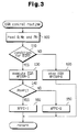
- FIG. 3 presents the flowchart that illustrates an "EGR control routine" for executing the EGR control.
- the ECU 41 periodically performs this routine at predetermined intervals.
- step 100 the ECU 41 reads the amount of intake air Q, the engine speed NE and the internal pressure PH based on the detection signals from the sensors 31, 35 and 36 respectively.
- step 110 the ECU 41 determines based on the value NE if the running condition of the engine 1 matches with the condition for executing EGR. When this condition is not met, the ECU 41 proceeds to step 120.
- step 120 the ECU 41 deactivates the EVR valve 19 to close the EGR valve 18 to thereby stop EGR.
- the ECU 41 sets an execution flag XFEGR for EGR to "0" and temporarily terminates the subsequent processing.
- step 110 When the execution condition is satisfied in step 110, on the other hand, the ECU 41 moves to step 130 where the ECU 41 activates the EVR valve 19 to open the EGR valve 18 for the execution of EGR. In this embodiment, the ECU 41 fully opens the EGR valve 18. At the same time, the ECU 41 sets the execution flag XFEGR for EGR to "1". The execution of EGR in this manner permits part of the exhaust gas to return to each combustion chamber 2 to thereby improve the combustion in each combustion chamber 2. This reduces the nitrogen oxide (NO x ) content in the exhaust gas discharged from each combustion chamber 2, thus improving the emissions.
- NO x nitrogen oxide
- step 140 the ECU 41 determines if the currently read internal pressure PH is equal to or greater than a predetermined reference value P1.
- the internal pressure PH and the reference value P1 both show negative pressures, so that the ECU 41 compares the negative pressure levels of the internal pressure PH and the reference value P1 with each other.
- the internal pressure PH is smaller than the reference value P1
- the negative pressure supplied into the housing 18b of the EGR valve 18 is relatively small.
- the ECU 41 therefore determines that the EGR valve 18 is not sufficiently open, and proceeds to step 150.
- the ECU 41 sets an examination flag XFFC to "0" indicating that examination of the EVR valve 19 associated with the permeability resistance of the filter 22 is not performed, and then temporarily terminates the subsequent processing.
- step 140 If the internal pressure PH is equal to or greater than the reference value P1 in step 140, however, the negative pressure supplied into the housing 18b of the EGR valve 18 is relatively large. The ECU 41 therefore determines that the EGR valve 18 is sufficiently open, and proceeds to step 160. In step 160, the ECU 41 sets the examination flag XFFC to "1" indicating that the examination associated with the filter 22 should be performed, and then temporarily terminates the subsequent processing.
- the examination associated with the filter 22 is permitted only during execution of EGR and when the EGR valve 18 is sufficiently open.
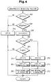
- Figure 4 presents the flowchart that illustrates an "abnormality detecting routine" for detecting an abnormality in the EGR system 16, particularly, an abnormality associated with the filter 22 based on the flags XFEGR and XFFC.
- the ECU 41 periodically performs this routine at predetermined intervals.
- step 200 the ECU 41 determines if the examination flag XFFC is "1". When the examination flag XFFC is "0", which means that the filter 22 is not to be examined, the ECU 41 proceeds to step 210. In this step 210, the ECU 41 resets a count value CFC for examination to "0" and then temporarily terminates the subsequent processing This count value CFC indicates the time from the point at which the closing of the EGR valve 18 has started.
- the ECU 41 determines if the execution flag XFEGR is "0" at step 220.
- the execution flag XFEGR is "1" which means that EGR is being performed, the ECU 41 executes the process in step 210 and then temporarily terminates the subsequent processing.
- the execution flag XFEGR is "0" the ECU 41 determines that the examination of the filter 22 is permitted or the EGR valve 18 has closed from the fully-open state and goes to step 230.
- step 230 the ECU 41 increments the required time from the point at which the closing of the EGR valve 18 has started, or the count value CFC reflecting the close responsiveness of the EGR valve 18 by "1".
- the ECU 41 determines if the count value CFC is equal to or greater than a reference value T1.
- This reference value T1 which has previously been determined through experiments, indicates that the permeability resistance of the filter 22 is abnormally large due to the clogging of the filter 22.
- the ECU 41 proceeds to step 250.
- step 250 the ECU 41 determines if the internal pressure PH is equal to or smaller than a predetermined reference value P2. When the internal pressure PH is greater than the reference value P2, the negative pressure supplied into the housing 18b is relatively large. The ECU 41 therefore determines that the EGR valve 18 is not sufficiently closed, and then temporarily terminates the subsequent processing.
- the negative pressure supplied into the housing 18b of the EGR valve 18 is relatively small. This means that the EGR valve 18 is sufficiently closed before the count value CFC reaches the reference value T1, and that the permeability resistance of the filter 22 connected to the atmospheric air port 19c of the EVR valve 19 is sufficiently small.
- the ECU 41 thus determines that the filter 22 is not badly clogged, i.e., that the permeability resistance of the filter 22 is not too large and proceeds to step 260.
- step 260 the ECU 41 resets the examination flag XFFC to "0".
- step 261 the ECU 41 turns off the diagnostic lamp 30.
- step 262 the ECU 41 saves a normal code indicating that the filter 22 is normal and the close responsiveness of the EGR valve 18 is normal into the backup RAM 45, and then temporarily terminates the subsequent processing.
- step 240 When the count value CFC is equal to or greater than the reference value T1 in step 240, the EGR valve 18 is not sufficiently closed when the count value CFC reaches the reference value T1. The ECU 41 thus determines that the filter 22 has been badly clogged and its permeability resistance is too large, and then it proceeds to step 270.
- step 270 the ECU 41 resets the examination flag XFFC to "0".
- the ECU 41 then turns on the diagnostic lamp 30 to inform the driver of an abnormality in the filter 22 in step 271.
- step 272 the ECU 41 determines that the close responsiveness of the EGR valve 18 has degraded due to the abnormality of the filter 22.
- the ECU 41 saves an abnormal code indicating that event in the backup RAM 45, and then it temporarily terminates the subsequent processing.
- the filter 22 is determined to be normal at this point of time.
- the filter 22 is determined to be abnormal at this point of time.
- the output port 19a of the EVR valve 19 and the atmospheric air port 19c are coupled together with the EGR valve 18 opened. Consequently, the atmospheric pressure is supplied into the housing 18b of the EGR valve 18 to close this valve 18.
- the filter 22 connected to the atmospheric air port 19c in this structure has been badly clogged so its permeability resistance is abnormally increased.
- the supply of atmospheric pressure into the housing 18b is delayed as indicated by the broken line in Figure 2(a). Accordingly, the time from the point at which the closing of the EGR valve 18 has started becomes larger than the standard value.
- the ECU 41 measures the required time as the count value CFC and compares the count value CFC with the predetermined reference value T1. When the count value CFC is greater than the reference value T1, the ECU 41 determines that the permeability resistance of the filter 22 associated with the EVR valve 19 is excessively large.
- the time required at the time the EGR valve 18 is closed depends on the delay of the supply of the atmospheric pressure to the housing 18b. This delay is originated from a response delay until the action of the atmospheric pressure reaches the output port 19a from the atmospheric air port 19c when the output port 19a is switched to the atmospheric air port 19c from the negative pressure port 19b, i.e., it is originated from the abnormal permeability resistance of the filter 22.
- the diagnostic lamp 30 is turned on when the abnormal permeability resistance of the filter 22 is detected. This allows the driver to quickly notice the abnormality. When the bad filter 22 is replaced, the close responsiveness of the EGR valve 18 will be set back to the normal state. In this sense, this embodiment can quickly cope with the deterioration of the emissions of the engine 1.
- this event is stored as an abnormal code in the backup RAM 45.
- the worker reads data from the backup RAM 45 when inspecting the engine 1, the worker can check the history of an abnormality in the filter 22. In this sense, it is possible to replace the filter 22 with a new one at the proper time and to cope with the deterioration of the emissions of the engine 1 quickly.
- FIG. 5 presents a schematic structural diagram illustrating a Diesel engine system according to this embodiment.
- the EGR valve 18 is provided with a lift sensor 37 instead of the pressure sensor 36 to detect the amount of lift LV as the actuation amount (opening) of the valve body 18c.
- the lift amount LV of the valve body 18c in the EGR valve 18 correlates with the internal pressure (negative pressure) PH of the housing 18b. Therefore, the abnormal permeability resistance of the filter 22 can be determined by causing the ECU 41 to monitor a change in the lift amount LV detected by the lift sensor 37 when the EGR valve 18 is closed.
- the flowchart in Figure 7 shows an "EGR control routine" in this embodiment, which corresponds with the routine in Figure 3.
- the individual steps 110-130, 150 and 160, excluding steps 300 and 340, are the same as the corresponding steps in the routine in Figure 3.
- the differences lie in that the ECU 41 reads the lift amount LV instead of the internal pressure PH in step 300 and the ECU 41 compares the lift amount LV with a predetermined reference value L1 instead of comparing the internal pressure PH with the reference value P1 in step 340.
- the flowchart in Figure 8 shows an "abnormality detecting routine" in this embodiment, which corresponds with the routine in Figure 4.
- the individual steps 200-240, 260-262 and 270-272, excluding step 450, are the same as the corresponding steps in the routine in Figure 4.
- the difference lies in that the ECU 41 compares the lift amount LV with a predetermined reference value L2 instead of comparing the internal pressure PH with the reference value P2 in step 450.
- FIGs 6(a), 6(b) and 6(c), like those in Figure 2, show the behaviors of various parameters in this embodiment.
- Figures 6(b) and 6(c) are substantially the same as Figures 2(b) and 2(c), while Figure 6(a) shows a change in the lift amount LV instead of a change in the internal pressure PH as in Figure 2(a). It is apparent that a change in the lift amount LV at an abnormal time in Figure 6(a) is slightly faster than a change in the internal pressure PH at an abnormal time in Figure 2(a).
- This embodiment can therefore have actions and advantages equivalent to those of the first embodiment.
- an abnormality in the filter 22 is determined by monitoring the response of the EGR valve 18 when the EGR valve 18 is closed from the fully-open state.
- an abnormality in the filter 22 may be determined by monitoring an intermediate response of the EGR valve 18 when the EGR valve 18 is closed to a predetermined angle from the fully-open state.
- the invention is adapted for use in a Diesel engine system according to the first and second embodiments, the invention may be adapted for use in a gasoline engine system.
- the abnormal permeability resistance of the filter 22 is detected as the abnormal permeability resistance which is associated with the atmospheric air port 19c of the EVR valve 19. If the atmospheric air port is connected to the air-intake passage, the abnormal permeability resistance of the air-intake passage may be detected as the abnormal permeability resistance associated with the atmospheric air port.
- the vacuum pump 21 is used as the negative pressure source.
- the proper portion of the air-intake passage where negative pressure is generated when the engine runs may be treated as the negative pressure source, in which case the negative pressure port of the EVR valve is connected to that portion.
- the EGR system (16) has a pressure responsive valve (EGR valve: 18) which is actuated in response to the negative pressure and atmospheric pressure for controlling EGR, and a pressure regulating valve (EVR valve: 19) which selectively supplies the negative pressure or the atmospheric pressure to the EGR valve (18) for its actuation.
- the EVR valve (19) has a port (19a) communicating with the EGR valve (18), a port (19b) for supplying the negative pressure and a port (19c) for supplying the atmospheric pressure.
- a filter (22) provided at the atmospheric air port (19c) serves to prevent dust or mud from entering the EVR valve (19).
- EVR valve (19) When the EGR valve (18) is to be open, the EVR valve (19) is actuated to supply the negative pressure to the EGR valve (18). When the EGR valve (18) is to be closed, the EVR valve (19) is actuated to supply the atmospheric pressure to the EGR valve (18).
- An electronic control unit (ECU: 41) measures the required time at the time of cloning the EGR valve (18) from the open state. When determining that the required time is greater than a reference value, the ECU (41) detects an abnormality in the EGR system (16) which has occurred due to the excessively large permeability resistance of the filter (22).
Landscapes
- Engineering & Computer Science (AREA)
- Chemical & Material Sciences (AREA)
- Combustion & Propulsion (AREA)
- Mechanical Engineering (AREA)
- General Engineering & Computer Science (AREA)
- Physics & Mathematics (AREA)
- Electromagnetism (AREA)
- Exhaust-Gas Circulating Devices (AREA)
- Output Control And Ontrol Of Special Type Engine (AREA)
- Electrical Control Of Air Or Fuel Supplied To Internal-Combustion Engine (AREA)
- Combined Controls Of Internal Combustion Engines (AREA)
Applications Claiming Priority (2)
| Application Number | Priority Date | Filing Date | Title |
|---|---|---|---|
| JP7315378A JPH09151807A (ja) | 1995-12-04 | 1995-12-04 | 内燃機関の排気ガス再循環装置のための異常検出装置 |
| JP315378/95 | 1995-12-04 |
Publications (2)
| Publication Number | Publication Date |
|---|---|
| EP0778409A2 true EP0778409A2 (de) | 1997-06-11 |
| EP0778409A3 EP0778409A3 (de) | 1998-01-14 |
Family
ID=18064694
Family Applications (1)
| Application Number | Title | Priority Date | Filing Date |
|---|---|---|---|
| EP96119377A Withdrawn EP0778409A3 (de) | 1995-12-04 | 1996-12-03 | Vorrichtung zum Auffinden von Anomalien in einem Abgasrückführsystem zur Verwendung in einer Brennkraftmachine |
Country Status (2)
| Country | Link |
|---|---|
| EP (1) | EP0778409A3 (de) |
| JP (1) | JPH09151807A (de) |
Cited By (1)
| Publication number | Priority date | Publication date | Assignee | Title |
|---|---|---|---|---|
| US6609059B2 (en) * | 2000-06-19 | 2003-08-19 | Honda Giken Kogyo Kabushiki Kaisha | Control system for internal combustion engine |
Citations (1)
| Publication number | Priority date | Publication date | Assignee | Title |
|---|---|---|---|---|
| JPH0719127A (ja) | 1993-06-30 | 1995-01-20 | Toyota Motor Corp | Egr装置付ディーゼルエンジンの燃料噴射量制御装置 |
Family Cites Families (6)
| Publication number | Priority date | Publication date | Assignee | Title |
|---|---|---|---|---|
| US4428355A (en) * | 1981-06-22 | 1984-01-31 | Toyo Kogyo Co., Ltd. | Exhaust gas recirculation control for internal combustion engines |
| JPS62214261A (ja) * | 1986-03-12 | 1987-09-21 | Fuji Heavy Ind Ltd | 排気ガス還流装置の故障診断装置 |
| JPH01310155A (ja) * | 1988-06-08 | 1989-12-14 | Mitsubishi Electric Corp | Egrシステムの異常検出装置 |
| JP2991760B2 (ja) * | 1990-09-29 | 1999-12-20 | マツダ株式会社 | 排気ガス還流装置の故障診断装置 |
| US5190017A (en) * | 1992-05-28 | 1993-03-02 | Ford Motor Company | Exhaust gas recirculation system fault detector |
| JPH08128360A (ja) * | 1994-11-01 | 1996-05-21 | Toyota Motor Corp | 排気ガス還流装置の故障診断装置 |
-
1995
- 1995-12-04 JP JP7315378A patent/JPH09151807A/ja active Pending
-
1996
- 1996-12-03 EP EP96119377A patent/EP0778409A3/de not_active Withdrawn
Patent Citations (1)
| Publication number | Priority date | Publication date | Assignee | Title |
|---|---|---|---|---|
| JPH0719127A (ja) | 1993-06-30 | 1995-01-20 | Toyota Motor Corp | Egr装置付ディーゼルエンジンの燃料噴射量制御装置 |
Cited By (1)
| Publication number | Priority date | Publication date | Assignee | Title |
|---|---|---|---|---|
| US6609059B2 (en) * | 2000-06-19 | 2003-08-19 | Honda Giken Kogyo Kabushiki Kaisha | Control system for internal combustion engine |
Also Published As
| Publication number | Publication date |
|---|---|
| JPH09151807A (ja) | 1997-06-10 |
| EP0778409A3 (de) | 1998-01-14 |
Similar Documents
| Publication | Publication Date | Title |
|---|---|---|
| EP0769612B1 (de) | Gerät zur Feststellung von Einlassdruckabnormalität einer Brennkraftmaschine | |
| US6687601B2 (en) | System for diagnosing an air handling mechanism of an internal combustion engine | |
| JP3680515B2 (ja) | 内燃機関の燃料系診断装置 | |
| EP0791736B1 (de) | Steuergerät für Abgasrückführungssystem für Dieselbrennkraftmaschine | |
| US6732707B2 (en) | Control system and method for internal combustion engine | |
| US5297527A (en) | Diagnosing apparatus of evaporation fuel control system of vehicle | |
| US6135085A (en) | Control apparatus for use in internal combustion engine | |
| US5119631A (en) | Apparatus and method for detecting abnormalities in a secondary air supplier | |
| US20080202482A1 (en) | EGR system for internal combustion engine | |
| US6836722B2 (en) | Method and system for diagnosing a failure of a rear oxygen sensor of a vehicle | |
| US6842690B2 (en) | Failure detection apparatus for an internal combustion engine | |
| US5542400A (en) | Apparatus and method for determining a failure of an EGR apparatus | |
| JPH08226354A (ja) | 内燃機関の排気還流装置における診断装置 | |
| US10975779B2 (en) | Engine system for determining abnormalities in an exhaust gas recirculation valve | |
| JPH07180615A (ja) | 内燃機関の排気還流制御装置 | |
| US20120037132A1 (en) | Method and device for operating an internal combustion engine having a compressor for compressing the air supplied to the internal combustion engine | |
| EP0778409A2 (de) | Vorrichtung zum Auffinden von Anomalien in einem Abgasrückführsystem zur Verwendung in einer Brennkraftmachine | |
| JPH0942021A (ja) | 内燃機関における燃焼改善機構の診断装置 | |
| JP3038865B2 (ja) | 排気還流装置の故障診断装置 | |
| JP2002349357A (ja) | 排出ガス環流システムの異常診断装置 | |
| CN113474548A (zh) | 发动机的egr装置 | |
| JPH06288303A (ja) | 内燃機関の排気還流装置における自己診断装置 | |
| JP2001193570A (ja) | 気体燃料エンジンの診断装置 | |
| JPH1089162A (ja) | 蒸発燃料供給系の故障診断方法およびその装置 | |
| JPH09105349A (ja) | 電子制御装置のフェールセーフ装置 |
Legal Events
| Date | Code | Title | Description |
|---|---|---|---|
| PUAI | Public reference made under article 153(3) epc to a published international application that has entered the european phase |
Free format text: ORIGINAL CODE: 0009012 |
|
| 17P | Request for examination filed |
Effective date: 19961203 |
|
| AK | Designated contracting states |
Kind code of ref document: A2 Designated state(s): DE FR GB |
|
| PUAL | Search report despatched |
Free format text: ORIGINAL CODE: 0009013 |
|
| AK | Designated contracting states |
Kind code of ref document: A3 Designated state(s): DE FR GB |
|
| 17Q | First examination report despatched |
Effective date: 19980624 |
|
| STAA | Information on the status of an ep patent application or granted ep patent |
Free format text: STATUS: THE APPLICATION IS DEEMED TO BE WITHDRAWN |
|
| 18D | Application deemed to be withdrawn |
Effective date: 19991021 |