EP0778472B1 - Circuit et procédé pour déterminer l'instant d'arrivée - Google Patents
Circuit et procédé pour déterminer l'instant d'arrivée Download PDFInfo
- Publication number
- EP0778472B1 EP0778472B1 EP96119493A EP96119493A EP0778472B1 EP 0778472 B1 EP0778472 B1 EP 0778472B1 EP 96119493 A EP96119493 A EP 96119493A EP 96119493 A EP96119493 A EP 96119493A EP 0778472 B1 EP0778472 B1 EP 0778472B1
- Authority
- EP
- European Patent Office
- Prior art keywords
- signal
- circuit
- pulse
- output pulse
- comparator
- Prior art date
- Legal status (The legal status is an assumption and is not a legal conclusion. Google has not performed a legal analysis and makes no representation as to the accuracy of the status listed.)
- Expired - Lifetime
Links
- 238000000034 method Methods 0.000 title claims description 10
- 230000003111 delayed effect Effects 0.000 claims description 34
- 238000005259 measurement Methods 0.000 claims description 14
- 238000001514 detection method Methods 0.000 claims description 13
- 230000000630 rising effect Effects 0.000 claims description 6
- 230000003287 optical effect Effects 0.000 description 31
- 238000004364 calculation method Methods 0.000 description 6
- 230000002238 attenuated effect Effects 0.000 description 4
- 238000004519 manufacturing process Methods 0.000 description 4
- 238000004458 analytical method Methods 0.000 description 3
- 238000010586 diagram Methods 0.000 description 3
- 230000004069 differentiation Effects 0.000 description 2
- 238000010304 firing Methods 0.000 description 2
- 230000007423 decrease Effects 0.000 description 1
- 238000012986 modification Methods 0.000 description 1
- 230000004048 modification Effects 0.000 description 1
- 238000012552 review Methods 0.000 description 1
- 230000007704 transition Effects 0.000 description 1
Images

Classifications
-
- G—PHYSICS
- G01—MEASURING; TESTING
- G01S—RADIO DIRECTION-FINDING; RADIO NAVIGATION; DETERMINING DISTANCE OR VELOCITY BY USE OF RADIO WAVES; LOCATING OR PRESENCE-DETECTING BY USE OF THE REFLECTION OR RERADIATION OF RADIO WAVES; ANALOGOUS ARRANGEMENTS USING OTHER WAVES
- G01S17/00—Systems using the reflection or reradiation of electromagnetic waves other than radio waves, e.g. lidar systems
- G01S17/02—Systems using the reflection of electromagnetic waves other than radio waves
- G01S17/06—Systems determining position data of a target
- G01S17/08—Systems determining position data of a target for measuring distance only
- G01S17/10—Systems determining position data of a target for measuring distance only using transmission of interrupted, pulse-modulated waves
-
- G—PHYSICS
- G01—MEASURING; TESTING
- G01S—RADIO DIRECTION-FINDING; RADIO NAVIGATION; DETERMINING DISTANCE OR VELOCITY BY USE OF RADIO WAVES; LOCATING OR PRESENCE-DETECTING BY USE OF THE REFLECTION OR RERADIATION OF RADIO WAVES; ANALOGOUS ARRANGEMENTS USING OTHER WAVES
- G01S7/00—Details of systems according to groups G01S13/00, G01S15/00, G01S17/00
- G01S7/48—Details of systems according to groups G01S13/00, G01S15/00, G01S17/00 of systems according to group G01S17/00
- G01S7/483—Details of pulse systems
- G01S7/486—Receivers
- G01S7/4865—Time delay measurement, e.g. time-of-flight measurement, time of arrival measurement or determining the exact position of a peak
-
- G—PHYSICS
- G01—MEASURING; TESTING
- G01S—RADIO DIRECTION-FINDING; RADIO NAVIGATION; DETERMINING DISTANCE OR VELOCITY BY USE OF RADIO WAVES; LOCATING OR PRESENCE-DETECTING BY USE OF THE REFLECTION OR RERADIATION OF RADIO WAVES; ANALOGOUS ARRANGEMENTS USING OTHER WAVES
- G01S7/00—Details of systems according to groups G01S13/00, G01S15/00, G01S17/00
- G01S7/48—Details of systems according to groups G01S13/00, G01S15/00, G01S17/00 of systems according to group G01S17/00
- G01S7/483—Details of pulse systems
- G01S7/486—Receivers
- G01S7/487—Extracting wanted echo signals, e.g. pulse detection
- G01S7/4873—Extracting wanted echo signals, e.g. pulse detection by deriving and controlling a threshold value
-
- G—PHYSICS
- G01—MEASURING; TESTING
- G01S—RADIO DIRECTION-FINDING; RADIO NAVIGATION; DETERMINING DISTANCE OR VELOCITY BY USE OF RADIO WAVES; LOCATING OR PRESENCE-DETECTING BY USE OF THE REFLECTION OR RERADIATION OF RADIO WAVES; ANALOGOUS ARRANGEMENTS USING OTHER WAVES
- G01S17/00—Systems using the reflection or reradiation of electromagnetic waves other than radio waves, e.g. lidar systems
- G01S17/02—Systems using the reflection of electromagnetic waves other than radio waves
- G01S17/06—Systems determining position data of a target
- G01S17/08—Systems determining position data of a target for measuring distance only
- G01S17/10—Systems determining position data of a target for measuring distance only using transmission of interrupted, pulse-modulated waves
- G01S17/18—Systems determining position data of a target for measuring distance only using transmission of interrupted, pulse-modulated waves wherein range gates are used
Definitions
- This invention relates in general to range finders and other related devices that use reflected optical/electromechanical energy to locate objects. More particularly, it relates to a method and circuit that detects optical energy reflected from an object, then estimates a relatively precise "time of arrival" for detected the detected optical energy.
- a range finder is an optical device used to calculate an estimate of the distance or "range” to a target.
- the range finder is typically placed in close proximity to an associated instrument, such as a military weapon.
- the estimated distance along with other information such as atmospheric conditions, is used by the weapon to calculate an estimate of the aim offsets that may be needed in firing at the target, thereby increasing aim accuracy.
- a small burst of laser light is sent to and reflected off of the target.
- the reflected light enters the range finder's optical system through one or more windows.
- the range finder determines the laser light's complete "time of flight,” which in turn requires a determination of the time at which the reflected light reaches the range finder, known generally as the "time of arrival.”
- Known range finders use simple threshold detection to determine "time of flight" and "time of arrival" of the reflected laser light.
- a conventional range finder light originated or reflected from the target is detected by a detector.
- the detector generates an analog signal representing the detected laser energy.
- the analog signal is fed to a simple threshold detection circuit that is typically formed from some form of a comparator circuit.
- One comparator input is coupled to a threshold, and the other comparator input is coupled to the incoming analog signal. Time of arrival is considered to have occurred when the comparator analog signal input exceeds the comparator threshold signal input. If the distance accuracy requirements are only within +/- 5 meters, and if the optical pulse is consistently narrow, for example less than about 6 nSec, threshold detection can be an adequate way to determine time of arrival.
- the size of the reflected optical energy pulse can be large or small depending upon the distance to the target and other factors such as atmospheric conditions or the target surface.
- the shape of the detected optical energy as a function of time is generally Gaussian.
- a very strong return pulse produces a large amount of energy above threshold for a long amount of time
- a weak return pulse produces a very small amount of energy that crosses the threshold for a very short amount of time. Accordingly, simple threshold detection has a built-in time ambiguity as to precisely when the pulse arrived.
- US 4,518,964 discloses a device for determining the arrival time of a fast or slow rising front pulse comprising a first comparator to which are applied at its inputs a delayed pulse and an attenuated non-delayed pulse, and a second comparator connected in parallel across the first, through an AND circuit receiving the pulse applied to the input of the device through a circuit connected to one of its inputs, acting on the noise and/or the signal.
- US 3,763,436 discloses a circuit for generating an output pulse with a precise time of occurrence relative to that input trigger signal regardless of varying amplitudes of the input trigger signal.
- the circuit comprises a comparator, the first input of which is supplied with a delayed signal and the second input of which is supplied with a non-delayed attenuated signal.
- the comparator compares both input signals and provides a positive signal if the delayed input signal is greater than the attenuated input signal.
- a very similar circuit is also disclosed in EP 0 357822 A1. Further, the paper “Constant-Fraction Circuits for Picosecond Photon Timing with Microchannel Plate Photomultipliers", Review of Scientific Instruments 64 (1993), S.
- Cova et al. relates to pulse-timing circuits and discloses a circuit in which a delayed input signal is compared with an attenuated input signal by a comparator.”
- a comparator There is a need for circuit and method of making precise and consistent time of arrival measurements on received optical pulse data of widely varying widths, thereby allowing the consistent and accurate calculation of distance estimates in range finders, target designators, and other similar systems.
- the present invention is an improved circuit and method of making precise time of arrival measurements on optical pulse data having widely varying widths.
- the invention goes beyond simple threshold "Time of Arrival" detection to allow the consistent and accurate calculation of distance estimates in range finders, target designators, and other similar systems.
- the inventive system as defined in claim 1 receives an analogue pulse that represents a received optical energy pulse.
- the received optical energy was preferably reflected or originated from a target object.
- the invention utilizes a delay circuit configuration to provide a delayed version of the analog pulse.
- the delay is set such that the analog pulse and the delayed analog pulse cross each other at a predetermined point in time.
- the cross-over consistently occurs at the same point on the analog pulse independent of the size or shape of the analog pulse.
- the cross-over occurs at approximately 70 % of the analog pulse amplitude.
- the cross-over point between the analog pulse and the delayed analog pulse triggers the leading edge of the time of arrival pulse.
- the circuit and method may be implemented by providing a detector, a delay circuit, a first comparator circuit, a second comparator circuit and a logic circuit.
- the detector output is fed to the delay circuit, the minus input of the first comparator and the plus input of the second comparator.
- the output of the delay circuit is fed to the minus input of the first comparator, and also provided to the plus input of the second comparator.
- the minus input of the second comparator is tied to a threshold voltage that sets a desired threshold noise level.
- the outputs of the first and second comparators are provided to a digital logic circuit that analyzes the comparator outputs and generates a pulse whose leading edge represents the optical data's time of arrival.
- the detector detects optical data and generates an analog output signal representing the optical data.
- the shape of the analog signal energy as a function of time is generally Gaussian.
- the analog signal can vary widely, with a very strong optical data input producing a large amount of energy for a long amount of time, and a weak optical data input producing a very small amount of energy for a very short amount of time.
- the first comparator circuit has as its plus and minus inputs the delayed analog signal and the original analog signal, respectively, while the second comparator circuit has as its plus and minus inputs the original analog signal and a threshold voltage, respectively.
- the second comparator outputs a pulse when the analog signal exceeds the noise threshold.
- the second comparator output is provided to the logic circuit to indicate to the logic circuit that the analog pulse is present. The logic circuit then looks at the first comparator output.
- the first comparator output generates a pulse when the original analog input crosses the delayed analog input.
- This cross-over consistently occurs at the same point independent of the size or shape of the analog pulse.
- the cross-over occurs at approximately 70 % of the analog pulse amplitude.
- the cross-over point between the original pulse and the delayed pulse triggers the logic circuit to generate the leading edge of the time of arrival pulse.
- the delay is set such that the analog pulse and the delayed analog pulse cross each other at a predetermined point in time.
- the cross-over consistently occurs at the same point on the analog pulse independent of the size or shape of the analog pulse.
- the cross-over occurs at approximately 70 % of the analog pulse amplitude.
- the cross-over point between the analog pulse and the delayed analog pulse triggers the leading edge of the time of arrival pulse.
- the disclosed delay line circuit provides a sufficiently precise and consistent time of arrival estimate. Accordingly, the circuit and method of present invention makes precise and consistent time of arrival measurements on received optical pulse data of widely varying widths, thereby allowing the consistent and accurate calculation of distance estimates in range finders, target designators, and other similar systems.
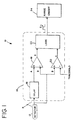
- Figure 1 is a diagram of a range finder system incorporating a delay line circuit and method embodying the present invention.
- the circuit accepts signal representing optical pulse data, then outputs a digital pulse (E) that is an estimate of optical pulse arrival time.
- E digital pulse
- Figures 2-5 show four related graphs that illustrate how optical pulse data passes through the circuit of Figure 1.
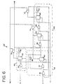
- Figure 6 is more detailed circuit diagram of an exemplary digital circuit for implementing the logic circuit shown in Figure 1.
- the present invention is an improved circuit and method of making precise time of arrival measurements on optical pulse data of relatively varying width.
- the invention goes beyond simple threshold detection to allow the consistent and accurate calculation of distance estimates in range finders, target designators, and other similar systems.
- a circuit embodying important features of the present invention is referred to herein as a delay line differentiation circuit.
- the delay line circuit may be inserted in a range finder or similar device to provide a precise estimate of time of arrival.
- a range finder is an optical device used to calculate an estimate of the distance or "range” to a target.
- the range finder is typically placed in close proximity to an associated instrument, such as a military weapon.
- the estimated distance along with other information such as atmospheric conditions, is used by the weapon to calculate an estimate of the aim offsets that may be needed in firing at the target, thereby increasing aim accuracy.
- a small burst of laser light is sent to and reflected off of the target. Reflected light enters the range finder's optical system, and the range finder calculates an estimate of distance. In estimating distance to the target, the range finder must determine the laser light's complete "time of flight,” which in turn requires a determination of the time at which the reflected light arrives at the range finder. This time is known generally as the "time of arrival.”
- Figure 1 illustrates a range finder system 10 incorporating the present invention.
- the range finder system 10 utilizes the disclosed delay line differentiation circuit 14 to determine "time of flight" and "time of arrival" of reflected laser light.
- the range finder system 10 includes a detector 12 coupled to a delay line circuit 14 coupled to a range finding circuit 24.
- the delay line circuit 14 includes a delay circuit 16, a first comparator 18, a second comparator 20 and a logic circuit 22.
- the delay circuit 16 receives the output from the detector 12.
- the detector 12 output is fed to the first comparator 18 and the second comparator 20.
- a threshold voltage (representing a threshold noise level) is provided to the second comparator 20.
- the outputs of the first and second comparators 18, 20 are coupled to a logic circuit 22 that generates a digital pulse (E) representing the time of arrival. This digital pulse is fed to a conventional range finding circuit 24.
- the detector 12 Light originated or reflected from the target is detected by the detector 12 in the range finder system 10.
- the detector 12 generates an analog signal (B) representing the detected laser energy.
- the analog signal is fed to, inter alia, the delay circuit 16 so that both the analog pulse and a delayed version of the analog pulse are available for analysis.
- the delay 12 is set such that the analog pulse and the delayed analog pulse cross each other at a predetermined point (shown at 30 in Figure 2). This cross-over consistently occurs at the same point independent of the size or shape of the analog pulse. Preferably, the cross-over occurs at approximately 70 % of the analog pulse amplitude.
- the cross-over point between the original pulse and the delayed pulse is used to trigger the leading edge of the time of arrival pulse, as described in more detail below.
- shape of the analog signal (B) generated by the detector 12 is Gaussian as a function of time.
- the analog signal (B) can vary widely, with a very strong optical data input producing a large amount of energy for a long amount of time, and a weak optical data input producing a very small amount of energy for a very short amount of time.
- the first comparator 18 compares the delayed analog signal (A) with the original analog signal (B), while the second comparator 20 compares the original analog signal (B) and a voltage representing a threshold noise level.
- the second comparator 20 outputs a pulse (C) when the analog signal (B) exceeds the noise threshold.
- the output of the second comparator 20 is provided to the logic circuit 22 to indicate to the logic circuit 22 that optical pulse data is present on the first comparator 18.
- the logic circuit 22 is then enabled to receive the output of the first comparator 18 which will provide an indication of the precise time of arrival of the input analog pulse (B).
- the first comparator 18 outputs a pulse (D) when the original analog input (B) crosses the delayed analog input (A) at the cross-over point 30.
- This cross-over consistently occurs at the same relative position on the signal waveform independent of the size or shape of the analog pulse.
- the cross-over 30 occurs at approximately 70% of the analog pulse amplitude.
- the cross-over point 30 between the original pulse (B) and the delayed pulse (A) triggers the logic circuit 22 to generate the leading edge of the time of arrival pulse (E).
- Figures 2-5 are graphs illustrating the various signals (A-E) that move through the range finding system 10, and more particularly, the delay line circuit 14.
- Figure 2 illustrates the analog signal (B) output from the detector 12, along with the delayed version (A) of the analog output from the delay circuit 16.
- Figure 3 illustrates the signal (C) that is output from the second comparator 20, and
- Figure 4 illustrates the signal (D) that is output from the first comparator 18.
- Figure 5 illustrates the digital pulse (E) that is output from the logic circuit 22.
- the digital pulse (E) represents the precise time of arrival of the analog input (B).
- Figure 6 is circuit diagram of a digital circuit 22' for implementing the logic circuit 22 shown in Figure 1.
- the circuit 22' is exemplary and not exclusive, and a wide variety of logic circuit designs could be used to implement the logic circuit 22.
- the disclosed circuit 22' is a configuration of conventional flip flops, exclusive-or gates and invertors, that work in tandem to produce the functions described herein for the logic circuit 22.
- the circuit 22' can be divided into three sections.
- the first section is a detection section 36 that includes an invertor 38 and a flip-flop 40 coupled to two exclusive-or gates 42, 44.
- the detection section 36 detects when a pulse is present on the output of the second comparator 20, and also enables the measurement section 50.
- the second section is a measurement section 50 that includes a flip-flop 52 coupled to an exclusive-or gate 54 and an invertor 56.
- the measurement section 50 is enabled by the detection section 36. Once enabled, the measurement section 50 generates a time of arrival pulse (E) when the analog signal (B) crosses the delayed version (A) of the analog signal as shown at reference number 30 in Figure 2.
- the third section is a spacing section 60 that includes two flip-flops 62, 64, two exclusive-or gates 66, 68 and an invertor 70.
- the spacing section 60 ensures that the detection section 36 only enables the measurement section 50 on a rising edge of the pulse (C) that is output from the second comparator 20. This ensures that the analysis of one optical pulse is completed before beginning the analysis of the next optical pulse, thus allowing the system 10 to respond to closely spaced targets.
- the logic circuit 22' is initialized when the reset (RS) input is at a logic "high,” thus setting all of the flip-flops 40, 52, 62, 64 to a logic “high” (via exclusive-or gates 72, 74, 76) and setting the time of arrival output (E) to a logic "low.”
- a rising edge on the output of the second comparator 20 clocks the flip-flop 40 of the detection circuit 36.
- the output of the flip-flop 40 enables the output of the first comparator 18 to propagate through an exclusive-or gate 54 which clocks the flip-flop 52 of the measurement section 50. Each successive time of arrival output (E) will only occur while the output of the second comparator 20 is high.
- the first pulse on the output of the first comparator 18 following a pulse on the output of the second comparator 20 always generates an output pulse regardless of the state of (C) when the signal (D) occurs. Once (C) goes low, another low to high transition is required before another time of arrival pulse (E) can be generated.
- the two flip-flops 62, 64 in the spacing section 60 ensures that this occurs correctly.
- the output time of arrival pulse (E) is generated, it clocks one of the flip-flops 62, 64 in the spacing section 60.
- the output of the first flip-flop 62 in the spacing section 60 then clocks another flip-flop 64 in the spacing section 60 only if the output signal (E) is low. If the output signal (E) is low, the flip-flop 62 is clocked and its output inhibits the generation of anymore time of arrival output pulses (E) until a new rising edge (C) is detected by the flip-flop 40.
- the delay 16 is set such that the analog pulse (B) and the delayed analog pulse (B) cross each other at a predetermined point 30.
- the cross-over consistently occurs in the same relative position 30 on the analog pulse independent of the size or shape of the analog pulse.
- the cross-over occurs at approximately 70 % of the analog pulse amplitude.
- the cross-over point between the analog pulse and the delayed analog pulse triggers the leading edge of the time of arrival pulse.
- the disclosed delay line circuit 14 provides a sufficiently precise and consistent time of arrival estimate. Accordingly, the circuit and method of present invention makes precise and consistent time of arrival measurements on received optical pulse data of widely varying widths, thereby allowing the consistent and accurate calculation of distance estimates in range finders, target designators, and other similar systems.
Landscapes
- Engineering & Computer Science (AREA)
- Physics & Mathematics (AREA)
- Computer Networks & Wireless Communication (AREA)
- General Physics & Mathematics (AREA)
- Radar, Positioning & Navigation (AREA)
- Remote Sensing (AREA)
- Electromagnetism (AREA)
- Optical Radar Systems And Details Thereof (AREA)
- Dc Digital Transmission (AREA)
- Optical Communication System (AREA)
- Pulse Circuits (AREA)
Claims (10)
- Circuit pour déterminer l'instant d'arrivée d'un signal (B), comprenant :caractérisé en ce queun circuit de retard (16) qui reçoit le signal (B) et qui génère un signal retardé (A) ;un premier comparateur (18) qui reçoit le signal (B) et ledit signal retardé (A) et qui génère une impulsion de sortie (D) lorsque ledit signal retardé (A) dépasse (30) ledit signal (B) ;un second comparateur (20) qui reçoit le signal (B) et un signal de seuil et qui génère une impulsion de sortie (C) lorsque ledit signal (B) dépasse ledit signal de seuil, etun circuit logique (22) qui reçoit ladite impulsion de sortie du premier comparateur (D) et ladite impulsion de sortie du second comparateur (C) et qui génère une impulsion de sortie (E) représentant l'instant d'arrivée du signal d'entrée (B),
ledit circuit logique comprend une section de détection (36) pour détecter l'impulsion de sortie (C), une section de mesure (50) pour générer l'instant d'impulsion d'arrivée (E) et une section d'espacement (60), dans lequel la section d'espacement (60) est adaptée pour valider la section de mesure (50) uniquement sur une arête montante de l'impulsion de sortie (C) du second comparateur. - Circuit selon la revendication 1, caractérisé en ce que ledit signal (B) a une amplitude maximale et en ce que ladite impulsion de sortie (D) est générée lorsque ledit signal retardé (A) dépasse (30) ledit signal (B) à un pourcentage prédéterminé de ladite amplitude maximale.
- Circuit selon la revendication 2, caractérisé en ce que ledit pourcentage prédéterminé est d'environ 70 %.
- Circuit selon l'une quelconque des revendications 1 à 3, caractérisé en ce que ledit circuit logique (22) interprète ladite impulsion de sortie du second comparateur (C) comme représentant le fait que ledit signal (B) a dépassé ledit signal de seuil ; et en ce que ledit circuit logique (22) interprète ladite impulsion de sortie du premier comparateur (D) comme représentant l'instant d'arrivée dudit signal (B).
- Circuit selon l'une quelconque des revendications 1 à 4, caractérisé par un détecteur (12) qui détecte l'énergie électromagnétique et qui génère ledit signal (B), ledit signal (B) représentant ladite énergie électromagnétique.
- Circuit selon la revendication 1, caractérisé par un circuit de télémétrie (24) accouplé à la sortie dudit circuit logique (22) et qui détermine une distance basée sur ladite impulsion de sortie (E).
- Procédé pour déterminer l'instant d'arrivée d'un signal (B), comprenant les étapes de :caractérisé en ce quegénération d'une version retardée (A) dudit signal (B) ;comparaison du signal (B) et dudit signal retardé (A) ;comparaison du signal (B) et d'un signal de seuil ;génération d'une seconde impulsion de sortie (C) lorsque ledit signal (B) dépasse ledit signal de seuil ;génération d'une première impulsion de sortie (D) lorsque ledit signal retardé (A) dépasse ledit signal (B) ;génération d'une impulsion de sortie (E) représentant l'instant d'arrivée du signal d'entrée,
la génération de l'impulsion de sortie (E) est validée uniquement sur une arête montante de la seconde impulsion de sortie (C). - Procédé selon la revendication 7, caractérisé en ce que ledit signal (B) a une amplitude maximale et en ce que ladite première impulsion de sortie (D) est générée lorsque ledit signal retardé (A) dépasse (30) ledit signal (B) à un pourcentage prédéterminé de ladite amplitude maximale.
- Procédé selon la revendication 8, caractérisé en ce que ledit pourcentage prédéterminé est d'environ 70 %.
- Procédé selon l'une quelconque des revendications 7 à 9, caractérisé par l'étape de détermination d'une distance basée sur ladite impulsion de sortie (E).
Applications Claiming Priority (2)
| Application Number | Priority Date | Filing Date | Title |
|---|---|---|---|
| US568326 | 1995-12-06 | ||
| US08/568,326 US5726742A (en) | 1995-12-06 | 1995-12-06 | Circuit and method for determining time of arrival |
Publications (3)
| Publication Number | Publication Date |
|---|---|
| EP0778472A2 EP0778472A2 (fr) | 1997-06-11 |
| EP0778472A3 EP0778472A3 (fr) | 1998-10-07 |
| EP0778472B1 true EP0778472B1 (fr) | 2003-03-12 |
Family
ID=24270832
Family Applications (1)
| Application Number | Title | Priority Date | Filing Date |
|---|---|---|---|
| EP96119493A Expired - Lifetime EP0778472B1 (fr) | 1995-12-06 | 1996-12-05 | Circuit et procédé pour déterminer l'instant d'arrivée |
Country Status (7)
| Country | Link |
|---|---|
| US (1) | US5726742A (fr) |
| EP (1) | EP0778472B1 (fr) |
| CA (1) | CA2191918C (fr) |
| DE (1) | DE69626611T2 (fr) |
| ES (1) | ES2194073T3 (fr) |
| IL (1) | IL119770A (fr) |
| NO (1) | NO965180L (fr) |
Families Citing this family (15)
| Publication number | Priority date | Publication date | Assignee | Title |
|---|---|---|---|---|
| JPH1048338A (ja) * | 1996-05-20 | 1998-02-20 | Olympus Optical Co Ltd | 距離測定装置 |
| JPH11214972A (ja) * | 1998-01-26 | 1999-08-06 | Mitsubishi Electric Corp | 半導体回路装置及びレシーバ回路 |
| JP2000065929A (ja) | 1998-08-21 | 2000-03-03 | Olympus Optical Co Ltd | 距離測定方法及び距離測定装置 |
| US6549594B1 (en) | 1999-05-28 | 2003-04-15 | Nortel Networks | Timing phase recovery method and apparatus |
| US6510186B1 (en) | 1999-05-28 | 2003-01-21 | Nortel Networks Limited | Signal time of arrival estimation method and system |
| FR2805682B1 (fr) * | 2000-02-28 | 2002-05-31 | St Microelectronics Sa | Dispositif de comparaison a tres base consommation |
| DE10026534A1 (de) * | 2000-05-27 | 2002-02-28 | Diehl Munitionssysteme Gmbh | Laserentfernungsmesseinrichtung für einen Zünder |
| US6842231B2 (en) * | 2002-09-30 | 2005-01-11 | Raytheon Company | Method for improved range accuracy in laser range finders |
| JP4037774B2 (ja) * | 2003-02-19 | 2008-01-23 | 富士通テン株式会社 | レーダ装置 |
| KR100692569B1 (ko) * | 2005-03-25 | 2007-03-13 | 삼성전자주식회사 | 저주파 신호를 이용한 거리 측정 방법 및 장치 |
| US7206062B2 (en) * | 2005-04-18 | 2007-04-17 | Raytheon Company | Readout integrated circuit (ROIC) for laser detection and ranging (LADAR) system and method for using same |
| KR100780195B1 (ko) * | 2006-11-06 | 2007-11-27 | 삼성전기주식회사 | 펄스 신호의 오버랩 검출 장치, 방법 및 이를 포함하는거리 측정 장치 |
| US11471697B2 (en) * | 2015-02-10 | 2022-10-18 | Andrew Hewitson | Laser therapy device and method of use |
| EP3489719B1 (fr) * | 2017-11-23 | 2023-09-20 | Trimble AB | Dispositif de mesure de la distance électronique amélioré |
| US12007510B2 (en) * | 2021-10-05 | 2024-06-11 | Lg Innotek Co., Ltd. | System and method for differential comparator-based time-of-flight measurement with amplitude estimation |
Family Cites Families (6)
| Publication number | Priority date | Publication date | Assignee | Title |
|---|---|---|---|---|
| US3763436A (en) * | 1971-12-27 | 1973-10-02 | Us Navy | Amplitude independent time of arrival detector |
| FR2497958A1 (fr) * | 1981-01-09 | 1982-07-16 | Thomson Csf | Dispositif de determination de l'instant d'arrivee d'impulsions, utilisation dans un equipement de mesure de distances et equipement de mesure comportant un tel dispositif |
| US4676660A (en) * | 1985-05-06 | 1987-06-30 | E-Systems, Inc. | Method and apparatus for generating a timing signal in a time-of-arrival detection system |
| CH670896A5 (fr) * | 1986-08-13 | 1989-07-14 | Zellweger Uster Ag | |
| EP0357822A1 (fr) * | 1988-09-08 | 1990-03-14 | Helmut K. Pinsch GmbH & Co. | Procédé et dispositif de mesure de la différence de temps entre des impulsions |
| US5382848A (en) * | 1992-09-11 | 1995-01-17 | Hughes Aircraft Company | Digital integrated time of arrival detector |
-
1995
- 1995-12-06 US US08/568,326 patent/US5726742A/en not_active Expired - Lifetime
-
1996
- 1996-12-03 CA CA002191918A patent/CA2191918C/fr not_active Expired - Fee Related
- 1996-12-04 NO NO965180A patent/NO965180L/no not_active Application Discontinuation
- 1996-12-05 EP EP96119493A patent/EP0778472B1/fr not_active Expired - Lifetime
- 1996-12-05 IL IL11977096A patent/IL119770A/xx not_active IP Right Cessation
- 1996-12-05 DE DE69626611T patent/DE69626611T2/de not_active Expired - Lifetime
- 1996-12-05 ES ES96119493T patent/ES2194073T3/es not_active Expired - Lifetime
Also Published As
| Publication number | Publication date |
|---|---|
| CA2191918C (fr) | 2000-04-11 |
| EP0778472A3 (fr) | 1998-10-07 |
| CA2191918A1 (fr) | 1997-06-07 |
| ES2194073T3 (es) | 2003-11-16 |
| IL119770A (en) | 1999-05-09 |
| NO965180L (no) | 1997-06-09 |
| DE69626611T2 (de) | 2004-02-12 |
| NO965180D0 (no) | 1996-12-04 |
| DE69626611D1 (de) | 2003-04-17 |
| EP0778472A2 (fr) | 1997-06-11 |
| IL119770A0 (en) | 1997-03-18 |
| US5726742A (en) | 1998-03-10 |
Similar Documents
| Publication | Publication Date | Title |
|---|---|---|
| EP0778472B1 (fr) | Circuit et procédé pour déterminer l'instant d'arrivée | |
| US4797679A (en) | Radio direction-finding using time of arrival measurements | |
| US11381246B2 (en) | Time-to-digital converter and converting methods | |
| US4553836A (en) | Method and apparatus for electrooptical distance measurement | |
| CN107843903B (zh) | 一种多阀值tdc高精度激光脉冲测距方法 | |
| US4849644A (en) | Optoelectric distance measuring apparatus with delay and zero cross detector | |
| CN109669188B (zh) | 多沿触发时间鉴别方法和脉冲式激光测距方法 | |
| US6657583B2 (en) | Pulse radar apparatus | |
| JPH1123709A (ja) | 距離測定装置 | |
| JPH05223928A (ja) | パルスレーダ | |
| EP1596219A1 (fr) | Traitement du signal pour déterminer le temps de retard | |
| US11327159B2 (en) | Electronic distance meter | |
| GB2191649A (en) | Radio direction-finding | |
| JP3365196B2 (ja) | レーダ装置 | |
| Kurtti et al. | Pulse width time walk compensation method for a pulsed time-of-flight laser rangefinder | |
| JPH05312950A (ja) | 距離測定装置および方法 | |
| JP2539749B2 (ja) | レ―ダ―測距装置の距離補正方法 | |
| JPS6254189A (ja) | 車両用ランダム変調レ−ダ装置 | |
| US4032756A (en) | Tacan-dme identity detector | |
| US20250052870A1 (en) | Signal transmitting and receiving system and method thereof | |
| JPH08220214A (ja) | 車両用レーダ装置 | |
| JP2856042B2 (ja) | 車両用レーダ装置 | |
| RU2333510C1 (ru) | Устройство определения дальности | |
| JP2000028721A (ja) | 測距装置 | |
| RU2191400C2 (ru) | Обнаружитель переотраженных сигналов |
Legal Events
| Date | Code | Title | Description |
|---|---|---|---|
| PUAI | Public reference made under article 153(3) epc to a published international application that has entered the european phase |
Free format text: ORIGINAL CODE: 0009012 |
|
| AK | Designated contracting states |
Kind code of ref document: A2 Designated state(s): DE ES FR GB |
|
| PUAL | Search report despatched |
Free format text: ORIGINAL CODE: 0009013 |
|
| AK | Designated contracting states |
Kind code of ref document: A3 Designated state(s): DE ES FR GB |
|
| RAP1 | Party data changed (applicant data changed or rights of an application transferred) |
Owner name: RAYTHEON COMPANY |
|
| RAP1 | Party data changed (applicant data changed or rights of an application transferred) |
Owner name: RAYTHEON COMPANY |
|
| 17P | Request for examination filed |
Effective date: 19990324 |
|
| 17Q | First examination report despatched |
Effective date: 20010228 |
|
| GRAH | Despatch of communication of intention to grant a patent |
Free format text: ORIGINAL CODE: EPIDOS IGRA |
|
| GRAH | Despatch of communication of intention to grant a patent |
Free format text: ORIGINAL CODE: EPIDOS IGRA |
|
| GRAA | (expected) grant |
Free format text: ORIGINAL CODE: 0009210 |
|
| AK | Designated contracting states |
Designated state(s): DE ES FR GB |
|
| REG | Reference to a national code |
Ref country code: GB Ref legal event code: FG4D |
|
| REF | Corresponds to: |
Ref document number: 69626611 Country of ref document: DE Date of ref document: 20030417 Kind code of ref document: P |
|
| ET | Fr: translation filed | ||
| REG | Reference to a national code |
Ref country code: ES Ref legal event code: FG2A Ref document number: 2194073 Country of ref document: ES Kind code of ref document: T3 |
|
| PLBE | No opposition filed within time limit |
Free format text: ORIGINAL CODE: 0009261 |
|
| STAA | Information on the status of an ep patent application or granted ep patent |
Free format text: STATUS: NO OPPOSITION FILED WITHIN TIME LIMIT |
|
| 26N | No opposition filed |
Effective date: 20031215 |
|
| PGFP | Annual fee paid to national office [announced via postgrant information from national office to epo] |
Ref country code: ES Payment date: 20041209 Year of fee payment: 9 |
|
| PG25 | Lapsed in a contracting state [announced via postgrant information from national office to epo] |
Ref country code: ES Free format text: LAPSE BECAUSE OF NON-PAYMENT OF DUE FEES Effective date: 20051207 |
|
| REG | Reference to a national code |
Ref country code: ES Ref legal event code: FD2A Effective date: 20051207 |
|
| REG | Reference to a national code |
Ref country code: FR Ref legal event code: PLFP Year of fee payment: 20 |
|
| PGFP | Annual fee paid to national office [announced via postgrant information from national office to epo] |
Ref country code: GB Payment date: 20151202 Year of fee payment: 20 Ref country code: DE Payment date: 20151201 Year of fee payment: 20 |
|
| PGFP | Annual fee paid to national office [announced via postgrant information from national office to epo] |
Ref country code: FR Payment date: 20151110 Year of fee payment: 20 |
|
| REG | Reference to a national code |
Ref country code: DE Ref legal event code: R071 Ref document number: 69626611 Country of ref document: DE |
|
| REG | Reference to a national code |
Ref country code: GB Ref legal event code: PE20 Expiry date: 20161204 |
|
| PG25 | Lapsed in a contracting state [announced via postgrant information from national office to epo] |
Ref country code: GB Free format text: LAPSE BECAUSE OF EXPIRATION OF PROTECTION Effective date: 20161204 |