EP0779174A2 - Réglage en longueur d'un siège - Google Patents
Réglage en longueur d'un siège Download PDFInfo
- Publication number
- EP0779174A2 EP0779174A2 EP96120174A EP96120174A EP0779174A2 EP 0779174 A2 EP0779174 A2 EP 0779174A2 EP 96120174 A EP96120174 A EP 96120174A EP 96120174 A EP96120174 A EP 96120174A EP 0779174 A2 EP0779174 A2 EP 0779174A2
- Authority
- EP
- European Patent Office
- Prior art keywords
- seat
- adjustment according
- guide rail
- adjustment
- rolling
- Prior art date
- Legal status (The legal status is an assumption and is not a legal conclusion. Google has not performed a legal analysis and makes no representation as to the accuracy of the status listed.)
- Withdrawn
Links
- 238000005096 rolling process Methods 0.000 claims abstract description 17
- 239000000969 carrier Substances 0.000 claims 1
- 238000010276 construction Methods 0.000 abstract description 3
- 238000006073 displacement reaction Methods 0.000 description 3
- 239000000428 dust Substances 0.000 description 2
- 239000000314 lubricant Substances 0.000 description 2
- 238000005461 lubrication Methods 0.000 description 2
- 238000004519 manufacturing process Methods 0.000 description 2
- 239000000463 material Substances 0.000 description 2
- 238000005299 abrasion Methods 0.000 description 1
- 230000005540 biological transmission Effects 0.000 description 1
- 230000000903 blocking effect Effects 0.000 description 1
- 238000000576 coating method Methods 0.000 description 1
- 230000000694 effects Effects 0.000 description 1
- 238000005538 encapsulation Methods 0.000 description 1
- 230000005923 long-lasting effect Effects 0.000 description 1
- 230000007257 malfunction Effects 0.000 description 1
- 239000002184 metal Substances 0.000 description 1
- 239000003973 paint Substances 0.000 description 1
- 238000007591 painting process Methods 0.000 description 1
- 239000002245 particle Substances 0.000 description 1
Images
Classifications
-
- B—PERFORMING OPERATIONS; TRANSPORTING
- B60—VEHICLES IN GENERAL
- B60N—SEATS SPECIALLY ADAPTED FOR VEHICLES; VEHICLE PASSENGER ACCOMMODATION NOT OTHERWISE PROVIDED FOR
- B60N2/00—Seats specially adapted for vehicles; Arrangement or mounting of seats in vehicles
- B60N2/02—Seats specially adapted for vehicles; Arrangement or mounting of seats in vehicles the seat or part thereof being movable, e.g. adjustable
- B60N2/04—Seats specially adapted for vehicles; Arrangement or mounting of seats in vehicles the seat or part thereof being movable, e.g. adjustable the whole seat being movable
- B60N2/06—Seats specially adapted for vehicles; Arrangement or mounting of seats in vehicles the seat or part thereof being movable, e.g. adjustable the whole seat being movable slidable
- B60N2/07—Slide construction
- B60N2/0735—Position and orientation of the slide as a whole
- B60N2/0747—Position and orientation of the slide as a whole the opening of the cross section being oriented in a direction different from the vertical, e.g. transversal
-
- B—PERFORMING OPERATIONS; TRANSPORTING
- B60—VEHICLES IN GENERAL
- B60N—SEATS SPECIALLY ADAPTED FOR VEHICLES; VEHICLE PASSENGER ACCOMMODATION NOT OTHERWISE PROVIDED FOR
- B60N2/00—Seats specially adapted for vehicles; Arrangement or mounting of seats in vehicles
- B60N2/02—Seats specially adapted for vehicles; Arrangement or mounting of seats in vehicles the seat or part thereof being movable, e.g. adjustable
- B60N2/04—Seats specially adapted for vehicles; Arrangement or mounting of seats in vehicles the seat or part thereof being movable, e.g. adjustable the whole seat being movable
- B60N2/06—Seats specially adapted for vehicles; Arrangement or mounting of seats in vehicles the seat or part thereof being movable, e.g. adjustable the whole seat being movable slidable
- B60N2/07—Slide construction
- B60N2/0702—Slide construction characterised by its cross-section
- B60N2/072—Complex cross-section, e.g. obtained by extrusion
-
- B—PERFORMING OPERATIONS; TRANSPORTING
- B60—VEHICLES IN GENERAL
- B60N—SEATS SPECIALLY ADAPTED FOR VEHICLES; VEHICLE PASSENGER ACCOMMODATION NOT OTHERWISE PROVIDED FOR
- B60N2/00—Seats specially adapted for vehicles; Arrangement or mounting of seats in vehicles
- B60N2/02—Seats specially adapted for vehicles; Arrangement or mounting of seats in vehicles the seat or part thereof being movable, e.g. adjustable
- B60N2/04—Seats specially adapted for vehicles; Arrangement or mounting of seats in vehicles the seat or part thereof being movable, e.g. adjustable the whole seat being movable
- B60N2/06—Seats specially adapted for vehicles; Arrangement or mounting of seats in vehicles the seat or part thereof being movable, e.g. adjustable the whole seat being movable slidable
- B60N2/08—Seats specially adapted for vehicles; Arrangement or mounting of seats in vehicles the seat or part thereof being movable, e.g. adjustable the whole seat being movable slidable characterised by the locking device
- B60N2/0812—Location of the latch
- B60N2/0825—Location of the latch outside the rail
Definitions
- the invention relates to a device for compensating the manufacturing-related tolerances between a first and a second guide rail of a pair of guide rails for the longitudinal adjustment of motor vehicle seats.
- a device for compensating for play is known from DE 16 80 269 A1, in which guide rails provided on the sill side and on the tunnel side, in FIG. 2 also in the middle of the vehicle floor, enable the adjustment of a vehicle seat in the direction of the vehicle's longitudinal axis.
- the sill side is the side of the vehicle on which the vehicle doors are attached, the sill representing the lower area of the manhole.
- the tunnel usually runs in the middle of the vehicle interior in the direction of the vehicle's longitudinal axis and acts as the load-bearing backbone of the vehicle underbody, whereby the power transmission elements can be accommodated in it.
- a first running rail is designed in such a way that it does not permit displacement of the seat to the transverse vehicle axis, while a second running rail permits movements in the transverse vehicle axis.
- DE 39 20 077 A1 discloses a further device for compensating for the play resulting from construction tolerances.
- the tolerances that occur are compensated for by means of a bolt loaded with an energy accumulator, which interacts with a clamping device.
- DE 43 30 133 A1 describes a device for tolerance compensation in which, in particular, the tilting of the sliding elements should be prevented if there is too much play between the guides or if the guide rails do not run parallel to one another and the sliding elements moving therein.
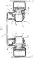
- Each guide rail 1 and 2 of the device according to the invention consists of at least two metal profiles 1.1 and 1.2 or 2.1 and 2.2 nested with one another, the respective outer profile 1.1 or 2.1 made of comparatively thick-walled material serving to absorb the high loads which are applied to the seat 5 and thus its guidance act, and the respective inner profile 1.2 or 2.2 made of comparatively thin-walled material, which is comprised by the respectively assigned outer profile 1.1 or 2.1, is provided for the actual guidance of the seat.
- the thin-walled guide profile 1.2 or 2.2 is firmly connected to the respectively assigned thick-walled holding profile 1.1 or 1.2; both profiles so nested are fixed via their outer profiles 1.1 and 2.1 at the points mentioned on the vehicle body.
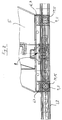
- supports 6 and 7 are attached to the bottom of the seat 5 in a fixed manner on the underside in the longitudinal direction on both sides at a distance.
- these supports 6 and 7 offer a firm hold to a locking device 8 shown schematically in FIG. 2 and, on the other hand, they have bearing eyes 9 and 11 attached at their end sections transversely to the direction of displacement of the seat.
- suitable friction-reducing bearing means preferably, as indicated in the exemplary embodiment, by means of roller bearings 12 or 13, a cylindrical roller body 14 or 15 is rotatably mounted in the bearing eyes.
- a profiled roller body which is approximately the same as a double truncated cone is connected, its truncated cone surfaces 16 and 17 having their smaller diameters lying opposite one another and in turn being connected by a cylindrical part 18 and 19, respectively that this shape results, so to speak, in a track roller.
- two such track rollers are arranged on each longitudinal side of the seat, one in the front and one in the rear.
- These track rollers which are made in one piece from the cylindrical rolling bodies 18 and 19 and the profiled, approximately double-frustoconical rolling bodies 16 and 17, are in fixed bearings 21 on one seat side - here on the sill side 3 - and in floating bearings 22 on the other seat side - tunnel side 4 pivoted about its axis of rotation.
- Those skilled in the art are familiar with the terms fixed and floating bearings known and therefore do not require special explanation.
- the track rollers with their outward-facing track edges are inserted into the sill and tunnel-side guide rails, whereby the vehicle seat is mounted in its longitudinal direction and can be moved.
- the axially displaceably loosely designed bearing 22 of the track rollers 16, 18 on the other side of the seat allows differences in the spacing of the guide rails to one another to a large extent to be easily compensated for without the guide mechanism becoming jammed in any way. Just as distance errors of the guide rails 1, 2 to one another have no influence on the smooth functioning of the adjustment, errors in the inclination of the guide rails to one another can also be compensated for. Due to the spherical configuration of the running surfaces 1.2 and 2.2 of the guide rails 1 and 2 and the inwardly curved running surface of the track rollers 16 and 17 (see FIG. 1), there is only one between the two surfaces Point contact is present, so that even when the rolling device is braced due to the inclination of the guide rails 1, 2, a slight displacement of the seat 5 is always possible because the rolling resistance remains limited to a very low level.
- Suitable encapsulation of the rotating parts guarantees a long-lasting, wear-free function of the roller device. Due to the rotatably mounted track rollers, there is no need to lubricate the guide rails, which means that the problem of malfunctions that result from soiling no longer arises. Dust and dirt particles can deposit on the curved guide rails, but will either fall off the curved surface when the seat is adjusted if the grain size is sufficient, or will be ground by the high point load of the track rollers on the curved surface and will therefore not impair the function into consideration.
- the ease of movement resulting from the low rolling resistance between the guide rail and track rollers ensures good one-hand operation of the longitudinal adjustment device.
- the seat can be easily moved to a different position with one hand after it is unlocked, which is particularly advantageous if the space behind the seat is to be reached. Since tilting does not occur in this device, the adjustment device is particularly suitable for the adjustment of seats that have an expansion have over the entire width of the interior of the vehicle.
- the seat After positioning the seat in its longitudinal position, it is fixed in the selected position by the locking device 8.
- the track rollers 16, 18 and 17, 19 of the rolling device are pressed onto the associated spherical running surface 1.2 or 2.2 of the guide rails in such a way that the entire remaining play between the guide rail and the rolling device is pressed out and the seat is held in its longitudinal position without rattling .
- This is particularly necessary when the seat is not occupied, since otherwise disturbing noises due to vehicle vibrations could arise from play in the guide rails.
Landscapes
- Engineering & Computer Science (AREA)
- Aviation & Aerospace Engineering (AREA)
- Transportation (AREA)
- Mechanical Engineering (AREA)
- Seats For Vehicles (AREA)
Applications Claiming Priority (2)
| Application Number | Priority Date | Filing Date | Title |
|---|---|---|---|
| DE1995147034 DE19547034A1 (de) | 1995-12-15 | 1995-12-15 | Sitzlängsverstellung |
| DE19547034 | 1995-12-15 |
Publications (2)
| Publication Number | Publication Date |
|---|---|
| EP0779174A2 true EP0779174A2 (fr) | 1997-06-18 |
| EP0779174A3 EP0779174A3 (fr) | 1998-09-02 |
Family
ID=7780318
Family Applications (1)
| Application Number | Title | Priority Date | Filing Date |
|---|---|---|---|
| EP96120174A Withdrawn EP0779174A3 (fr) | 1995-12-15 | 1996-12-16 | Réglage en longueur d'un siège |
Country Status (2)
| Country | Link |
|---|---|
| EP (1) | EP0779174A3 (fr) |
| DE (1) | DE19547034A1 (fr) |
Cited By (2)
| Publication number | Priority date | Publication date | Assignee | Title |
|---|---|---|---|---|
| WO2005053995A3 (fr) * | 2003-11-28 | 2006-02-16 | Brose Fahrzeugteile | Dispositif pour guider deux sous-ensembles deplaçables l'un par rapport a l'autre d'un vehicule automobile, notamment d'un siege de vehicule automobile, le long d'un sens de guidage |
| WO2005051701A3 (fr) * | 2003-11-28 | 2006-02-16 | Brose Fahrzeugteile | Dispositif pour guider deux ensembles deplaçables l'un par rapport a l'autre d'un vehicule automobile, notamment d'un siege de vehicule automobile, le long d'un sens de guidage |
Families Citing this family (7)
| Publication number | Priority date | Publication date | Assignee | Title |
|---|---|---|---|---|
| DE19738383A1 (de) | 1997-09-03 | 1999-03-04 | Johnson Controls Gmbh | Sitzführung zur längspositionsverstellbaren Halterung eines Fahrzeugsitzes |
| DE10340897A1 (de) * | 2003-09-01 | 2005-03-24 | Brose Fahrzeugteile Gmbh & Co. Kommanditgesellschaft, Coburg | Führungsschienenanordnung für eine Verstelleinrichtung in Kraftfahrzeugen |
| DE102015215630A1 (de) | 2015-08-17 | 2017-02-23 | Brose Fahrzeugteile Gmbh & Co. Kommanditgesellschaft, Bamberg | Vorrichtung zum manuellen und/oder elektromotorischen Verstellen oder Feststellen eines ersten Fahrzeugteils und eines zweiten Fahrzeugteils relativ zueinander |
| DE102015215631A1 (de) | 2015-08-17 | 2017-02-23 | Brose Fahrzeugteile Gmbh & Co. Kommanditgesellschaft, Bamberg | Vorrichtung zum manuellen und/oder elektromotorischen Verstellen oder Feststellen eines ersten Fahrzeugteils und eines zweiten Fahrzeugteils relativ zueinander |
| DE102015215627A1 (de) | 2015-08-17 | 2017-02-23 | Brose Fahrzeugteile Gmbh & Co. Kommanditgesellschaft, Bamberg | Vorrichtung zum manuellen und/oder elektromotorischen Verstellen oder Feststellen eines ersten Fahrzeugteils und eines zweiten Fahrzeugteils relativ zueinander |
| DE102019216976A1 (de) * | 2019-10-23 | 2021-04-29 | Brose Fahrzeugteile SE & Co. Kommanditgesellschaft, Coburg | Sitztiefenverstelleinrichtung für einen Fahrzeugsitz |
| DE102019216331A1 (de) * | 2019-10-23 | 2021-04-29 | Brose Fahrzeugteile SE & Co. Kommanditgesellschaft, Coburg | Sitztiefenverstelleinrichtung für einen Fahrzeugsitz |
Family Cites Families (9)
| Publication number | Priority date | Publication date | Assignee | Title |
|---|---|---|---|---|
| GB318798A (en) * | 1928-11-20 | 1929-09-12 | Arthur Sam Cheston | Improvements relating to runner-fittings for sliding seats for vehicles |
| US3460794A (en) * | 1967-06-14 | 1969-08-12 | Gen Motors Corp | Seat adjuster |
| DE1680269A1 (de) * | 1967-10-04 | 1972-02-03 | Keiper Recaro Gmbh Co | Vorrichtung zur Befestigung eines Sitzes an einem Boden |
| DE3642441C1 (en) * | 1986-12-12 | 1988-09-01 | Audi Ag | Rail and roller guide |
| DE3920077A1 (de) * | 1988-06-30 | 1990-01-04 | Volkswagen Ag | In schienen gefuehrter fahrzeugsitz |
| US5118062A (en) * | 1990-12-17 | 1992-06-02 | Bruno Archambault | Seat attachment assembly |
| US5348261A (en) * | 1992-12-21 | 1994-09-20 | General Motors Corporation | Low mass manual two-way seat adjuster |
| DE4330133A1 (de) * | 1993-09-06 | 1995-03-16 | Naue Johnson Controls Eng | Schienenführung für Fahrzeugsitze |
| DE19519153C2 (de) * | 1994-05-30 | 1998-12-17 | Linde & Wiemann Gmbh Kg | Führung für verstellbare Fahrzeugsitze |
-
1995
- 1995-12-15 DE DE1995147034 patent/DE19547034A1/de not_active Withdrawn
-
1996
- 1996-12-16 EP EP96120174A patent/EP0779174A3/fr not_active Withdrawn
Cited By (3)
| Publication number | Priority date | Publication date | Assignee | Title |
|---|---|---|---|---|
| WO2005053995A3 (fr) * | 2003-11-28 | 2006-02-16 | Brose Fahrzeugteile | Dispositif pour guider deux sous-ensembles deplaçables l'un par rapport a l'autre d'un vehicule automobile, notamment d'un siege de vehicule automobile, le long d'un sens de guidage |
| WO2005051701A3 (fr) * | 2003-11-28 | 2006-02-16 | Brose Fahrzeugteile | Dispositif pour guider deux ensembles deplaçables l'un par rapport a l'autre d'un vehicule automobile, notamment d'un siege de vehicule automobile, le long d'un sens de guidage |
| US7404537B2 (en) | 2003-11-28 | 2008-07-29 | Brose Fahrzeugteile Gmbh & Co Kg, Coburg | Device for guiding two sub-assemblies of a motor vehicle which are displaceable in relation to one another, in particular of a motor vehicle seat, in a guide direction |
Also Published As
| Publication number | Publication date |
|---|---|
| EP0779174A3 (fr) | 1998-09-02 |
| DE19547034A1 (de) | 1997-06-19 |
Similar Documents
| Publication | Publication Date | Title |
|---|---|---|
| EP1066773B1 (fr) | Glissière | |
| DE10229385B4 (de) | Einrichtung zur Befestigung eines Rückhaltesystems eines Verkehrs- oder Transportmittels | |
| AT512934B1 (de) | Schubladenausziehführung | |
| EP1007385B1 (fr) | Guide destiné à la fixation d'un siège de véhicule et au réglage de la position longitudinale de ce siège | |
| EP2183494B1 (fr) | Systeme de guidage lineaire comportant un rail a profile creux | |
| DE3643777C1 (de) | Tuerhalter fuer Kraftwagentueren | |
| EP3624641B1 (fr) | Dispositif de guidage | |
| DE102012100287B4 (de) | Fahrzeugsitz | |
| EP2983943A1 (fr) | Dispositif de réglage longitudinal d'un siège de véhicule et siège de véhicule | |
| DE102020203210A1 (de) | Lenksäule für ein Kraftfahrzeug | |
| EP3752694B1 (fr) | Dispositif de stationnement de voiture | |
| DE69518785T2 (de) | Führungsrolleneinheit | |
| EP2183493B1 (fr) | Systeme de guidage lineaire | |
| DE19547034A1 (de) | Sitzlängsverstellung | |
| DE19857814A1 (de) | Schiene zur Führung von Laufschienen von Kfz-Komponenten und Verfahren zu ihrer Herstellung | |
| DE19519153C2 (de) | Führung für verstellbare Fahrzeugsitze | |
| EP0568900B1 (fr) | Système à deux glissières de forme en U à encombrement réduit, en particulier pour sièges de véhicules automobiles | |
| DE10104077A1 (de) | Verstellmechanismus für eine Armlehne einer Kraftfahrzeugtür | |
| EP0517951B1 (fr) | Dispositif de fixation d'un corps porteur d'un élément de roulement pour un guidage linéaire | |
| DE9315132U1 (de) | Drehgelenk | |
| DE102020202523A1 (de) | Verstelleinrichtung für einen Fahrzeugsitz | |
| DE9011413U1 (de) | Linearantrieb | |
| DE3420221A1 (de) | Verstellvorrichtung fuer fahrzeugsitze | |
| DE68923174T2 (de) | Anordnung für fahrzeugsitze. | |
| EP2014854A2 (fr) | Actionnement de porte pour au moins un vantail de porte dans un véhicule |
Legal Events
| Date | Code | Title | Description |
|---|---|---|---|
| PUAI | Public reference made under article 153(3) epc to a published international application that has entered the european phase |
Free format text: ORIGINAL CODE: 0009012 |
|
| AK | Designated contracting states |
Kind code of ref document: A2 Designated state(s): DE FR GB |
|
| PUAL | Search report despatched |
Free format text: ORIGINAL CODE: 0009013 |
|
| AK | Designated contracting states |
Kind code of ref document: A3 Designated state(s): DE FR GB |
|
| STAA | Information on the status of an ep patent application or granted ep patent |
Free format text: STATUS: THE APPLICATION HAS BEEN WITHDRAWN |
|
| 18W | Application withdrawn |
Withdrawal date: 19981103 |