EP0779435A2 - Verin hydraulique - Google Patents
Verin hydraulique Download PDFInfo
- Publication number
- EP0779435A2 EP0779435A2 EP96119960A EP96119960A EP0779435A2 EP 0779435 A2 EP0779435 A2 EP 0779435A2 EP 96119960 A EP96119960 A EP 96119960A EP 96119960 A EP96119960 A EP 96119960A EP 0779435 A2 EP0779435 A2 EP 0779435A2
- Authority
- EP
- European Patent Office
- Prior art keywords
- working cylinder
- damping
- shut
- hydraulic
- mandrel
- Prior art date
- Legal status (The legal status is an assumption and is not a legal conclusion. Google has not performed a legal analysis and makes no representation as to the accuracy of the status listed.)
- Granted
Links
Images

Classifications
-
- F—MECHANICAL ENGINEERING; LIGHTING; HEATING; WEAPONS; BLASTING
- F15—FLUID-PRESSURE ACTUATORS; HYDRAULICS OR PNEUMATICS IN GENERAL
- F15B—SYSTEMS ACTING BY MEANS OF FLUIDS IN GENERAL; FLUID-PRESSURE ACTUATORS, e.g. SERVOMOTORS; DETAILS OF FLUID-PRESSURE SYSTEMS, NOT OTHERWISE PROVIDED FOR
- F15B15/00—Fluid-actuated devices for displacing a member from one position to another; Gearing associated therewith
- F15B15/20—Other details, e.g. assembly with regulating devices
- F15B15/22—Other details, e.g. assembly with regulating devices for accelerating or decelerating the stroke
- F15B15/222—Other details, e.g. assembly with regulating devices for accelerating or decelerating the stroke having a piston with a piston extension or piston recess which throttles the main fluid outlet as the piston approaches its end position
Definitions
- the invention relates to a hydraulic working cylinder, in particular a plunger cylinder for a forklift or the like, according to the preamble of claim 1.
- a working piston movable in a working cylinder additionally has an end-side brake chamber in which a brake piston is axially movable so that when it is supported on the front end of the working cylinder, part of the pressure medium remains in a brake chamber.
- the pressure medium can be drained off via an annular gap between the brake chamber wall and the brake piston in such a way that end position damping is achieved with the further axial movement of the working piston toward the front end of the working cylinder.
- the invention has for its object to provide a hydraulic working cylinder that enables a sufficiently strong end position damping with little technical effort and structurally simple components even with long braking distances of the working piston and makes additional control components unnecessary.
- a particularly simple engagement component is provided with the shut-off mandrel supported in the region of the cylinder base and axially movable for controlling the pressure medium, with which a double function is achieved in the working cylinder via a corresponding interaction with the pressure medium in the damping and working position.
- the shut-off mandrel has a damping tube part that can be adapted to any cylinder length with a long braking distance, with which, in the damping position, for example on working cylinders for forklifts, lifting devices and the like, a sufficiently strong and, in particular, progressively adjustable damping effect is achieved over long braking distances.
- the shut-off mandrel can be axially adjusted in the direction of flow against a stop in the manner of a valve adjustment in such a way that an efficiently controllable, additional non-return valve dispensable working cylinder is created with this shut-off mandrel as a single component.
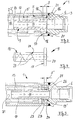
- FIG. 1 shows a working cylinder, designated overall by 1, in the cylinder interior 2 of which is surrounded by the cylinder tube 2 ', a movable working piston 5 with an essentially tubular piston rod 5' is provided.
- the cylinder working space is provided at the end with a cylinder base 3 and a cylinder head 4 as closure parts.
- a pressure medium can be supplied via a hydraulic connection 6 in such a way that the working piston 5 is displaced in the working direction (arrow A) towards the cylinder head 4.
- the working piston 5 moves back into the illustrated starting position according to FIG. 1, this movement (arrow B) being braked in the region of end position damping 7 near the cylinder base 3.
- the working cylinder 1 has in this end-side end position damping region 7 a shut-off mandrel 9 designed in the manner of a damping piston, which is held at one end directly in the region of the cylinder base 3 and on the other hand with its mandrel region designed as damping tube part 10 when in the stroke end position toward the cylinder head 4 the working piston 5 protrudes freely into the cylinder working space 2 (FIG. 2).
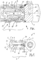
- the return movement of the working piston 5 (arrow B), which can be seen from the combination of the movement phases according to FIGS. 2 and 3, illustrates the respective engagement conditions, the shut-off pin 9 when the initial damping position is reached (FIG. 2) into a through hole 12 forming a brake chamber the piston rod 5 'engages and after this beginning of the damping phase a part of the pressure medium to be discharged is passed between a brake chamber wall 13 and the damping tube part 10 and via its interior 14 to the hydraulic connection 6. At the same time, the shut-off pin 9 rests on the end face of the cylinder base 3 and the length L of the damping tube part 10 defines the damping path during the damping phase.
- the shut-off pin 9 can be axially displaced towards a stop 15 under the action of the pressure medium introduced via the hydraulic connection 6 in the pressure flow direction (arrow A in FIG. 1).
- the shut-off mandrel 9 thus has a double function, since it can be placed in a sealing engagement both in the damping position in the manner of a valve body on the inner edge region 16 of the hydraulic connection 6 at the end, and when the working pressure is introduced it can be moved into an open position in the manner of a check valve.
- the shut-off pin 9 is provided at one end on the damping tube part 10 with a flange part 17 directed towards the edge region 16 of the hydraulic connection 6, which in turn engages at least in regions in a support groove 18 provided in the wall of the cylinder tube 2 'as a stop 15 in this way that the axial displacement of the shut-off mandrel 9 is limited by their width dimension S (FIG. 3).
- the flange part 17 Towards the edge region 16 of the hydraulic connection 6, the flange part 17 has a molded attachment 20 which forms the end face sealing engagement in the damping position.
- the flange part 17 of the shut-off mandrel 9 is displaced in the pressure direction against the stop 15' in such a way that at the same time a passage position (gap D) is reached in the end region of the flange part 17 and the pressure medium can flow into the cylinder interior 2 via a mold recess 21 which acts as an axial flow channel.
- a passage position (gap D) is reached in the end region of the flange part 17 and the pressure medium can flow into the cylinder interior 2 via a mold recess 21 which acts as an axial flow channel.
- two opposing shaped recesses 21, 21 ' are provided, which are effective as flow channels in the region of the support groove 18.
- shut-off mandrel 9 instead of the flange part, it has a support shoulder 23 which engages directly in the front end region of the working cylinder 1, the axial stop 15 ′ of the shut-off mandrel 9 of one with a groove in its engagement region with the cylinder base 3 24 corresponding spring ring 25 is formed in the support projection 23.
- the shut-off pin 9 with the support attachment 23, the latter has a front seat surface 26 which forms the sealing engagement directly in the damping position.
- the support projection 23 or the surrounding wall area of the working cylinder 1 is provided with an axial groove 27 which is effective in the open position as the flow channel. It is also conceivable that several such flow channels (not shown) are provided in this area.
- This recess 28 is advantageously formed by a spiral groove 29, with which a progressive damping of the working piston 5 can be achieved, for example, in that the spiral groove 29 has a flow cross section which increases toward the free end of the damping tube part 10.
- Fig. 7 a similar to the embodiment of FIG. 1 designed end position damping 7 is provided, the shut-off pin 9 being held in the installed position by a compression spring 30 such that a deviation of the shut-off pin also occurs in the free support position (FIG. 2) from the coaxial position with the cylinder longitudinal axis 31 is safely avoided.
Landscapes
- Engineering & Computer Science (AREA)
- Physics & Mathematics (AREA)
- Fluid Mechanics (AREA)
- Mechanical Engineering (AREA)
- General Engineering & Computer Science (AREA)
- Actuator (AREA)
- Fluid-Damping Devices (AREA)
- Fluid-Pressure Circuits (AREA)
- Vehicle Body Suspensions (AREA)
- Braking Arrangements (AREA)
- Forklifts And Lifting Vehicles (AREA)
Applications Claiming Priority (2)
| Application Number | Priority Date | Filing Date | Title |
|---|---|---|---|
| DE29519991U DE29519991U1 (de) | 1995-12-16 | 1995-12-16 | Hydraulischer Arbeitszylinder |
| DE29519991U | 1995-12-16 |
Publications (3)
| Publication Number | Publication Date |
|---|---|
| EP0779435A2 true EP0779435A2 (fr) | 1997-06-18 |
| EP0779435A3 EP0779435A3 (fr) | 1998-07-29 |
| EP0779435B1 EP0779435B1 (fr) | 2001-11-14 |
Family
ID=8016834
Family Applications (1)
| Application Number | Title | Priority Date | Filing Date |
|---|---|---|---|
| EP96119960A Expired - Lifetime EP0779435B1 (fr) | 1995-12-16 | 1996-12-12 | Verin hydraulique |
Country Status (5)
| Country | Link |
|---|---|
| EP (1) | EP0779435B1 (fr) |
| AT (1) | ATE208858T1 (fr) |
| DE (2) | DE29519991U1 (fr) |
| DK (1) | DK0779435T3 (fr) |
| ES (1) | ES2168431T3 (fr) |
Families Citing this family (2)
| Publication number | Priority date | Publication date | Assignee | Title |
|---|---|---|---|---|
| DE202004011993U1 (de) * | 2004-07-30 | 2005-12-08 | Liebherr-Werk Nenzing Ges.M.B.H. | Kolben-/Zylindereinheit |
| DE202020004533U1 (de) | 2020-10-28 | 2022-02-04 | Bümach Engineering International B.V. | Endlagengedämpfter Arbeitszylinder |
Citations (1)
| Publication number | Priority date | Publication date | Assignee | Title |
|---|---|---|---|---|
| DE1241712B (de) | 1963-06-26 | 1967-06-01 | Hydraulik Rochlitz Veb | Bremsung fuer hydraulische oder pneumatische Geraete, vorzugsweise fuer Arbeitszylinder mit nur einfach gefuehrter Kolbenstange |
Family Cites Families (6)
| Publication number | Priority date | Publication date | Assignee | Title |
|---|---|---|---|---|
| US2338845A (en) * | 1941-10-10 | 1944-01-11 | Curtiss Wright Corp | Hydraulic piston snubber |
| US3419114A (en) * | 1967-09-18 | 1968-12-31 | Houdaille Industries Inc | Hydraulic action devices with inertia insensitive snubbing circuit |
| CH551570A (de) * | 1974-03-04 | 1974-07-15 | Bbc Brown Boveri & Cie | Hydraulischer antrieb, insbesondere fuer elektrische schaltgeraete. |
| DE2755878A1 (de) * | 1977-12-15 | 1979-06-21 | Licentia Gmbh | Hydraulik-arbeitszylinder mit einstellbarer daempfung |
| DE3445481A1 (de) * | 1983-12-16 | 1985-06-27 | E.A. Storz Gmbh & Co Kg, 7200 Tuttlingen | Hydraulikzylinderaggregat |
| JP2696743B2 (ja) * | 1993-12-09 | 1998-01-14 | エスエムシー株式会社 | 速度制御機構付ロッドレスシリンダ |
-
1995
- 1995-12-16 DE DE29519991U patent/DE29519991U1/de not_active Expired - Lifetime
-
1996
- 1996-12-12 DK DK96119960T patent/DK0779435T3/da active
- 1996-12-12 ES ES96119960T patent/ES2168431T3/es not_active Expired - Lifetime
- 1996-12-12 DE DE59608194T patent/DE59608194D1/de not_active Expired - Lifetime
- 1996-12-12 EP EP96119960A patent/EP0779435B1/fr not_active Expired - Lifetime
- 1996-12-12 AT AT96119960T patent/ATE208858T1/de active
Patent Citations (1)
| Publication number | Priority date | Publication date | Assignee | Title |
|---|---|---|---|---|
| DE1241712B (de) | 1963-06-26 | 1967-06-01 | Hydraulik Rochlitz Veb | Bremsung fuer hydraulische oder pneumatische Geraete, vorzugsweise fuer Arbeitszylinder mit nur einfach gefuehrter Kolbenstange |
Also Published As
| Publication number | Publication date |
|---|---|
| DK0779435T3 (da) | 2002-03-11 |
| ES2168431T3 (es) | 2002-06-16 |
| DE29519991U1 (de) | 1997-04-10 |
| EP0779435A3 (fr) | 1998-07-29 |
| EP0779435B1 (fr) | 2001-11-14 |
| ATE208858T1 (de) | 2001-11-15 |
| DE59608194D1 (de) | 2001-12-20 |
Similar Documents
| Publication | Publication Date | Title |
|---|---|---|
| DE2459340C2 (de) | Stufenlos höhenverstellbare Säule | |
| DE69016218T2 (de) | Hydraulisch blockierbare Gasfeder. | |
| DE2942455C2 (fr) | ||
| DE3707046C2 (fr) | ||
| DE2127187C3 (de) | Steuervorrichtung für eine hydraulische Hilfskraftlenkung | |
| DE3831459C2 (fr) | ||
| EP0544734B1 (fr) | Direction assistee | |
| EP1525144A1 (fr) | Valve de regulation de pression | |
| EP0607370B2 (fr) | Piston a soupape centrale pour systemes hydrauliques de freinage | |
| DE69413722T2 (de) | Hydraulischer Hauptzylinder | |
| EP0937206A1 (fr) | Moteur de positionnement pneumatique ou hydraulique muni d'un dispositif de desenclenchement | |
| EP0200182A2 (fr) | Vanne-pilote hydraulique du type robinet à piston | |
| DE19610834C1 (de) | Hauptzylinder | |
| DE4405581A1 (de) | Geberzylinder | |
| WO2020038513A1 (fr) | Poussoir pour une pompe à carburant ou pour un mécanisme d'actionnement de soupape | |
| EP0407751B1 (fr) | Valve relais pour systèmes de freinage commandés par fluide sous pression pour véhicules | |
| EP0779435B1 (fr) | Verin hydraulique | |
| DE2925885A1 (de) | Pneumatischer tuerzylinder | |
| DE19921553A1 (de) | Druckabschalteinrichtung für eine Hilfskraftlenkung in den Endstellungen des Lenkausschlages | |
| DE2213367A1 (de) | Den bremsdruck in den druckmittelzylindern der hinterachse steuerndes regelventil fuer kraftfahrzeugbremsanlagen | |
| EP0684391B1 (fr) | Vérin à fluide sous pression | |
| EP3992469B1 (fr) | Cylindre de travail amorti en fin de course | |
| EP1988297A2 (fr) | Cylindre hydraulique doté d'un amortissement de fin de course variable | |
| DE9418042U1 (de) | Hydraulikzylinder mit Endlagendämpfung | |
| EP1348900A2 (fr) | Soupape hydraulique, en particulier soupape d'excédent de débit |
Legal Events
| Date | Code | Title | Description |
|---|---|---|---|
| PUAI | Public reference made under article 153(3) epc to a published international application that has entered the european phase |
Free format text: ORIGINAL CODE: 0009012 |
|
| AK | Designated contracting states |
Kind code of ref document: A2 Designated state(s): AT BE CH DE DK ES FR GB IT LI NL |
|
| PUAL | Search report despatched |
Free format text: ORIGINAL CODE: 0009013 |
|
| AK | Designated contracting states |
Kind code of ref document: A3 Designated state(s): AT BE CH DE DK ES FR GB IT LI NL |
|
| 17P | Request for examination filed |
Effective date: 19980910 |
|
| 17Q | First examination report despatched |
Effective date: 20000320 |
|
| RAP1 | Party data changed (applicant data changed or rights of an application transferred) |
Owner name: BUEMACH ENGINEERING INTERNATIONAL B.V. |
|
| GRAG | Despatch of communication of intention to grant |
Free format text: ORIGINAL CODE: EPIDOS AGRA |
|
| GRAG | Despatch of communication of intention to grant |
Free format text: ORIGINAL CODE: EPIDOS AGRA |
|
| GRAH | Despatch of communication of intention to grant a patent |
Free format text: ORIGINAL CODE: EPIDOS IGRA |
|
| GRAH | Despatch of communication of intention to grant a patent |
Free format text: ORIGINAL CODE: EPIDOS IGRA |
|
| GRAA | (expected) grant |
Free format text: ORIGINAL CODE: 0009210 |
|
| AK | Designated contracting states |
Kind code of ref document: B1 Designated state(s): AT BE CH DE DK ES FR GB IT LI NL |
|
| REF | Corresponds to: |
Ref document number: 208858 Country of ref document: AT Date of ref document: 20011115 Kind code of ref document: T |
|
| REG | Reference to a national code |
Ref country code: CH Ref legal event code: EP |
|
| REG | Reference to a national code |
Ref country code: CH Ref legal event code: NV Representative=s name: PATENTANWALTSBUERO FELDMANN AG |
|
| REF | Corresponds to: |
Ref document number: 59608194 Country of ref document: DE Date of ref document: 20011220 |
|
| REG | Reference to a national code |
Ref country code: GB Ref legal event code: IF02 |
|
| ET | Fr: translation filed | ||
| GBT | Gb: translation of ep patent filed (gb section 77(6)(a)/1977) |
Effective date: 20020124 |
|
| REG | Reference to a national code |
Ref country code: DK Ref legal event code: T3 |
|
| REG | Reference to a national code |
Ref country code: ES Ref legal event code: FG2A Ref document number: 2168431 Country of ref document: ES Kind code of ref document: T3 |
|
| PLBE | No opposition filed within time limit |
Free format text: ORIGINAL CODE: 0009261 |
|
| STAA | Information on the status of an ep patent application or granted ep patent |
Free format text: STATUS: NO OPPOSITION FILED WITHIN TIME LIMIT |
|
| 26N | No opposition filed | ||
| REG | Reference to a national code |
Ref country code: CH Ref legal event code: PFA Owner name: BUEMACH ENGINEERING INTERNATIONAL B.V. Free format text: BUEMACH ENGINEERING INTERNATIONAL B.V.#BAANDER 61R#7811 HH EMMEN (NL) -TRANSFER TO- BUEMACH ENGINEERING INTERNATIONAL B.V.#BAANDER 61R#7811 HH EMMEN (NL) |
|
| REG | Reference to a national code |
Ref country code: FR Ref legal event code: PLFP Year of fee payment: 20 |
|
| PGFP | Annual fee paid to national office [announced via postgrant information from national office to epo] |
Ref country code: DE Payment date: 20150820 Year of fee payment: 20 Ref country code: GB Payment date: 20151207 Year of fee payment: 20 Ref country code: DK Payment date: 20151216 Year of fee payment: 20 |
|
| PGFP | Annual fee paid to national office [announced via postgrant information from national office to epo] |
Ref country code: BE Payment date: 20151028 Year of fee payment: 20 Ref country code: AT Payment date: 20151223 Year of fee payment: 20 Ref country code: ES Payment date: 20151221 Year of fee payment: 20 Ref country code: NL Payment date: 20151228 Year of fee payment: 20 Ref country code: FR Payment date: 20151228 Year of fee payment: 20 |
|
| PGFP | Annual fee paid to national office [announced via postgrant information from national office to epo] |
Ref country code: CH Payment date: 20160329 Year of fee payment: 20 Ref country code: IT Payment date: 20151203 Year of fee payment: 20 |
|
| REG | Reference to a national code |
Ref country code: DE Ref legal event code: R071 Ref document number: 59608194 Country of ref document: DE |
|
| REG | Reference to a national code |
Ref country code: NL Ref legal event code: MK Effective date: 20161211 |
|
| REG | Reference to a national code |
Ref country code: DK Ref legal event code: EUP Effective date: 20161212 |
|
| REG | Reference to a national code |
Ref country code: CH Ref legal event code: PL |
|
| REG | Reference to a national code |
Ref country code: GB Ref legal event code: PE20 Expiry date: 20161211 |
|
| PG25 | Lapsed in a contracting state [announced via postgrant information from national office to epo] |
Ref country code: GB Free format text: LAPSE BECAUSE OF EXPIRATION OF PROTECTION Effective date: 20161211 |
|
| REG | Reference to a national code |
Ref country code: AT Ref legal event code: MK07 Ref document number: 208858 Country of ref document: AT Kind code of ref document: T Effective date: 20161212 |
|
| PG25 | Lapsed in a contracting state [announced via postgrant information from national office to epo] |
Ref country code: ES Free format text: LAPSE BECAUSE OF EXPIRATION OF PROTECTION Effective date: 20161213 |