EP0779562A1 - Rouleau comportant un corps en mousse et procédé de production du rouleau - Google Patents
Rouleau comportant un corps en mousse et procédé de production du rouleau Download PDFInfo
- Publication number
- EP0779562A1 EP0779562A1 EP19970100552 EP97100552A EP0779562A1 EP 0779562 A1 EP0779562 A1 EP 0779562A1 EP 19970100552 EP19970100552 EP 19970100552 EP 97100552 A EP97100552 A EP 97100552A EP 0779562 A1 EP0779562 A1 EP 0779562A1
- Authority
- EP
- European Patent Office
- Prior art keywords
- layer
- foam
- electrically conductive
- tube
- roll
- Prior art date
- Legal status (The legal status is an assumption and is not a legal conclusion. Google has not performed a legal analysis and makes no representation as to the accuracy of the status listed.)
- Granted
Links
Images


Classifications
-
- B—PERFORMING OPERATIONS; TRANSPORTING
- B29—WORKING OF PLASTICS; WORKING OF SUBSTANCES IN A PLASTIC STATE IN GENERAL
- B29C—SHAPING OR JOINING OF PLASTICS; SHAPING OF MATERIAL IN A PLASTIC STATE, NOT OTHERWISE PROVIDED FOR; AFTER-TREATMENT OF THE SHAPED PRODUCTS, e.g. REPAIRING
- B29C44/00—Shaping by internal pressure generated in the material, e.g. swelling or foaming ; Producing porous or cellular expanded plastics articles
- B29C44/02—Shaping by internal pressure generated in the material, e.g. swelling or foaming ; Producing porous or cellular expanded plastics articles for articles of definite length, i.e. discrete articles
- B29C44/12—Incorporating or moulding on preformed parts, e.g. inserts or reinforcements
- B29C44/1228—Joining preformed parts by the expanding material
- B29C44/1242—Joining preformed parts by the expanding material the preformed parts being concentric
-
- B—PERFORMING OPERATIONS; TRANSPORTING
- B29—WORKING OF PLASTICS; WORKING OF SUBSTANCES IN A PLASTIC STATE IN GENERAL
- B29C—SHAPING OR JOINING OF PLASTICS; SHAPING OF MATERIAL IN A PLASTIC STATE, NOT OTHERWISE PROVIDED FOR; AFTER-TREATMENT OF THE SHAPED PRODUCTS, e.g. REPAIRING
- B29C44/00—Shaping by internal pressure generated in the material, e.g. swelling or foaming ; Producing porous or cellular expanded plastics articles
- B29C44/02—Shaping by internal pressure generated in the material, e.g. swelling or foaming ; Producing porous or cellular expanded plastics articles for articles of definite length, i.e. discrete articles
- B29C44/12—Incorporating or moulding on preformed parts, e.g. inserts or reinforcements
- B29C44/14—Incorporating or moulding on preformed parts, e.g. inserts or reinforcements the preformed part being a lining
-
- F—MECHANICAL ENGINEERING; LIGHTING; HEATING; WEAPONS; BLASTING
- F16—ENGINEERING ELEMENTS AND UNITS; GENERAL MEASURES FOR PRODUCING AND MAINTAINING EFFECTIVE FUNCTIONING OF MACHINES OR INSTALLATIONS; THERMAL INSULATION IN GENERAL
- F16C—SHAFTS; FLEXIBLE SHAFTS; ELEMENTS OR CRANKSHAFT MECHANISMS; ROTARY BODIES OTHER THAN GEARING ELEMENTS; BEARINGS
- F16C13/00—Rolls, drums, discs, or the like; Bearings or mountings therefor
-
- G—PHYSICS
- G03—PHOTOGRAPHY; CINEMATOGRAPHY; ANALOGOUS TECHNIQUES USING WAVES OTHER THAN OPTICAL WAVES; ELECTROGRAPHY; HOLOGRAPHY
- G03G—ELECTROGRAPHY; ELECTROPHOTOGRAPHY; MAGNETOGRAPHY
- G03G15/00—Apparatus for electrographic processes using a charge pattern
- G03G15/02—Apparatus for electrographic processes using a charge pattern for laying down a uniform charge, e.g. for sensitising; Corona discharge devices
- G03G15/0208—Apparatus for electrographic processes using a charge pattern for laying down a uniform charge, e.g. for sensitising; Corona discharge devices by contact, friction or induction, e.g. liquid charging apparatus
- G03G15/0216—Apparatus for electrographic processes using a charge pattern for laying down a uniform charge, e.g. for sensitising; Corona discharge devices by contact, friction or induction, e.g. liquid charging apparatus by bringing a charging member into contact with the member to be charged, e.g. roller, brush chargers
- G03G15/0233—Structure, details of the charging member, e.g. chemical composition, surface properties
-
- G—PHYSICS
- G03—PHOTOGRAPHY; CINEMATOGRAPHY; ANALOGOUS TECHNIQUES USING WAVES OTHER THAN OPTICAL WAVES; ELECTROGRAPHY; HOLOGRAPHY
- G03G—ELECTROGRAPHY; ELECTROPHOTOGRAPHY; MAGNETOGRAPHY
- G03G15/00—Apparatus for electrographic processes using a charge pattern
- G03G15/06—Apparatus for electrographic processes using a charge pattern for developing
- G03G15/08—Apparatus for electrographic processes using a charge pattern for developing using a solid developer, e.g. powder developer
- G03G15/0806—Apparatus for electrographic processes using a charge pattern for developing using a solid developer, e.g. powder developer on a donor element, e.g. belt, roller
- G03G15/0818—Apparatus for electrographic processes using a charge pattern for developing using a solid developer, e.g. powder developer on a donor element, e.g. belt, roller characterised by the structure of the donor member, e.g. surface properties
-
- G—PHYSICS
- G03—PHOTOGRAPHY; CINEMATOGRAPHY; ANALOGOUS TECHNIQUES USING WAVES OTHER THAN OPTICAL WAVES; ELECTROGRAPHY; HOLOGRAPHY
- G03G—ELECTROGRAPHY; ELECTROPHOTOGRAPHY; MAGNETOGRAPHY
- G03G15/00—Apparatus for electrographic processes using a charge pattern
- G03G15/14—Apparatus for electrographic processes using a charge pattern for transferring a pattern to a second base
- G03G15/16—Apparatus for electrographic processes using a charge pattern for transferring a pattern to a second base of a toner pattern, e.g. a powder pattern, e.g. magnetic transfer
- G03G15/1665—Apparatus for electrographic processes using a charge pattern for transferring a pattern to a second base of a toner pattern, e.g. a powder pattern, e.g. magnetic transfer by introducing the second base in the nip formed by the recording member and at least one transfer member, e.g. in combination with bias or heat
- G03G15/167—Apparatus for electrographic processes using a charge pattern for transferring a pattern to a second base of a toner pattern, e.g. a powder pattern, e.g. magnetic transfer by introducing the second base in the nip formed by the recording member and at least one transfer member, e.g. in combination with bias or heat at least one of the recording member or the transfer member being rotatable during the transfer
- G03G15/1685—Structure, details of the transfer member, e.g. chemical composition
-
- G—PHYSICS
- G03—PHOTOGRAPHY; CINEMATOGRAPHY; ANALOGOUS TECHNIQUES USING WAVES OTHER THAN OPTICAL WAVES; ELECTROGRAPHY; HOLOGRAPHY
- G03G—ELECTROGRAPHY; ELECTROPHOTOGRAPHY; MAGNETOGRAPHY
- G03G15/00—Apparatus for electrographic processes using a charge pattern
- G03G15/20—Apparatus for electrographic processes using a charge pattern for fixing, e.g. by using heat
- G03G15/2003—Apparatus for electrographic processes using a charge pattern for fixing, e.g. by using heat using heat
- G03G15/2014—Apparatus for electrographic processes using a charge pattern for fixing, e.g. by using heat using heat using contact heat
- G03G15/2053—Structural details of heat elements, e.g. structure of roller or belt, eddy current, induction heating
- G03G15/2057—Structural details of heat elements, e.g. structure of roller or belt, eddy current, induction heating relating to the chemical composition of the heat element and layers thereof
-
- G—PHYSICS
- G03—PHOTOGRAPHY; CINEMATOGRAPHY; ANALOGOUS TECHNIQUES USING WAVES OTHER THAN OPTICAL WAVES; ELECTROGRAPHY; HOLOGRAPHY
- G03G—ELECTROGRAPHY; ELECTROPHOTOGRAPHY; MAGNETOGRAPHY
- G03G15/00—Apparatus for electrographic processes using a charge pattern
- G03G15/20—Apparatus for electrographic processes using a charge pattern for fixing, e.g. by using heat
- G03G15/2003—Apparatus for electrographic processes using a charge pattern for fixing, e.g. by using heat using heat
- G03G15/2014—Apparatus for electrographic processes using a charge pattern for fixing, e.g. by using heat using heat using contact heat
- G03G15/206—Structural details or chemical composition of the pressure elements and layers thereof
-
- G—PHYSICS
- G03—PHOTOGRAPHY; CINEMATOGRAPHY; ANALOGOUS TECHNIQUES USING WAVES OTHER THAN OPTICAL WAVES; ELECTROGRAPHY; HOLOGRAPHY
- G03G—ELECTROGRAPHY; ELECTROPHOTOGRAPHY; MAGNETOGRAPHY
- G03G21/00—Arrangements not provided for by groups G03G13/00 - G03G19/00, e.g. cleaning, elimination of residual charge
- G03G21/0005—Arrangements not provided for by groups G03G13/00 - G03G19/00, e.g. cleaning, elimination of residual charge for removing solid developer or debris from the electrographic recording medium
- G03G21/0058—Arrangements not provided for by groups G03G13/00 - G03G19/00, e.g. cleaning, elimination of residual charge for removing solid developer or debris from the electrographic recording medium using a roller or a polygonal rotating cleaning member; Details thereof, e.g. surface structure
-
- B—PERFORMING OPERATIONS; TRANSPORTING
- B29—WORKING OF PLASTICS; WORKING OF SUBSTANCES IN A PLASTIC STATE IN GENERAL
- B29L—INDEXING SCHEME ASSOCIATED WITH SUBCLASS B29C, RELATING TO PARTICULAR ARTICLES
- B29L2031/00—Other particular articles
- B29L2031/32—Wheels, pinions, pulleys, castors or rollers, Rims
-
- Y—GENERAL TAGGING OF NEW TECHNOLOGICAL DEVELOPMENTS; GENERAL TAGGING OF CROSS-SECTIONAL TECHNOLOGIES SPANNING OVER SEVERAL SECTIONS OF THE IPC; TECHNICAL SUBJECTS COVERED BY FORMER USPC CROSS-REFERENCE ART COLLECTIONS [XRACs] AND DIGESTS
- Y10—TECHNICAL SUBJECTS COVERED BY FORMER USPC
- Y10T—TECHNICAL SUBJECTS COVERED BY FORMER US CLASSIFICATION
- Y10T428/00—Stock material or miscellaneous articles
- Y10T428/13—Hollow or container type article [e.g., tube, vase, etc.]
- Y10T428/1352—Polymer or resin containing [i.e., natural or synthetic]
- Y10T428/1355—Elemental metal containing [e.g., substrate, foil, film, coating, etc.]
- Y10T428/1359—Three or more layers [continuous layer]
-
- Y—GENERAL TAGGING OF NEW TECHNOLOGICAL DEVELOPMENTS; GENERAL TAGGING OF CROSS-SECTIONAL TECHNOLOGIES SPANNING OVER SEVERAL SECTIONS OF THE IPC; TECHNICAL SUBJECTS COVERED BY FORMER USPC CROSS-REFERENCE ART COLLECTIONS [XRACs] AND DIGESTS
- Y10—TECHNICAL SUBJECTS COVERED BY FORMER USPC
- Y10T—TECHNICAL SUBJECTS COVERED BY FORMER US CLASSIFICATION
- Y10T428/00—Stock material or miscellaneous articles
- Y10T428/13—Hollow or container type article [e.g., tube, vase, etc.]
- Y10T428/1352—Polymer or resin containing [i.e., natural or synthetic]
- Y10T428/1386—Natural or synthetic rubber or rubber-like compound containing
-
- Y—GENERAL TAGGING OF NEW TECHNOLOGICAL DEVELOPMENTS; GENERAL TAGGING OF CROSS-SECTIONAL TECHNOLOGIES SPANNING OVER SEVERAL SECTIONS OF THE IPC; TECHNICAL SUBJECTS COVERED BY FORMER USPC CROSS-REFERENCE ART COLLECTIONS [XRACs] AND DIGESTS
- Y10—TECHNICAL SUBJECTS COVERED BY FORMER USPC
- Y10T—TECHNICAL SUBJECTS COVERED BY FORMER US CLASSIFICATION
- Y10T428/00—Stock material or miscellaneous articles
- Y10T428/13—Hollow or container type article [e.g., tube, vase, etc.]
- Y10T428/1352—Polymer or resin containing [i.e., natural or synthetic]
- Y10T428/139—Open-ended, self-supporting conduit, cylinder, or tube-type article
- Y10T428/1393—Multilayer [continuous layer]
-
- Y—GENERAL TAGGING OF NEW TECHNOLOGICAL DEVELOPMENTS; GENERAL TAGGING OF CROSS-SECTIONAL TECHNOLOGIES SPANNING OVER SEVERAL SECTIONS OF THE IPC; TECHNICAL SUBJECTS COVERED BY FORMER USPC CROSS-REFERENCE ART COLLECTIONS [XRACs] AND DIGESTS
- Y10—TECHNICAL SUBJECTS COVERED BY FORMER USPC
- Y10T—TECHNICAL SUBJECTS COVERED BY FORMER US CLASSIFICATION
- Y10T428/00—Stock material or miscellaneous articles
- Y10T428/249921—Web or sheet containing structurally defined element or component
- Y10T428/249953—Composite having voids in a component [e.g., porous, cellular, etc.]
Definitions
- the present invention relates to a roll, such as a charging roll, image developing roll, image transfer roll, cleaning roll, pressure roll, for use in electrophotographic copying machines, printers or the like, and particularly to a charging roll.
- This invention also relates to a method of producing such a roll as indicated above.
- a corona discharge device In conventional electrophotographic copying machines or printers, a corona discharge device has been used for electrostatically charging a surface of a photosensitive body or drum so that the surface is uniformly provided with a predetermined electric potential.
- the use of the corona discharge device results in some problems, such as (1) the necessity of high-voltage power supply, (2) relatively low charging efficiency, (3) the occurrence of a high level of ozone, and (4) local variation in the degree of charging of the photosensitive drum due to contamination of wires.
- contact type charging methods in particular, a roll charging method which uses an electrically conductive roll as a charging roll.
- the charging roll is rotated with a photosensitive drum which is positively moved or driven by a suitable drive device, with the surface of the roll being in pressed contact with that of the drum.
- a given voltage is applied to a center shaft or core of the charging roll, electrical charges are directly given to the surface of the photosensitive drum, whereby the drum surface is charged with a predetermined electrical potential.
- the applied voltage consists solely of a DC component, microscopic variation arises in contact between the charging roll and the photosensitive body, which results in spot-like charging variation.
- a voltage consisting of a DC component and an AC component superimposed on the DC component is applied to the charging roll.
- the frequency of the AC electric field is determined depending upon a process speed, that is, the frequency increases with an increase in the process speed.
- the AC component of the voltage has a low frequency when the processing is effected at a low speed, and has a high frequency when the processing is effected at a high speed.
- FIG. 3 The construction of the charging roll used in the above-described charging method is generally shown in Fig. 3, by way of example.
- an electrically conductive elastic layer 4 formed of a low-hardness electrically conductive rubber composition is formed on an outer circumferential surface of a center shaft or core 2.
- the preventive layer 6 serves to prevent a softening agent from oozing or migrating out of the conductive elastic layer 4.
- the AC component of the voltage causes force to act between the drum and the charging roll, which force depends on the frequency of the AC component. Consequently, the photosensitive drum, which has a thin metallic pipe as a base or core member, vibrates and generates noise.
- vibration and noise are conventionally prevented by various damping methods, such as coating the inner surface of the photosensitive drum with a damping coating, or filling the inside of the drum with a damping material. Otherwise, a noise insulating device is needed for reducing sound or noise which leaks from a housing accommodating the photosensitive drum and charging roll.
- the width of the nip between the drum and roll is likely to be small at the opposite ends of the roll and to be large at a middle portion of the roll.
- a clearance tends to be formed between the middle portion of the roll and the drum, thereby causing the photosensitive drum to be non-uniformly or unevenly charged.
- a charging roll which is constructed such that a foam layer consisting of an electrically conductive foam body is formed on the outer circumference of the center shaft, and such that a resistance adjusting layer and a protective layer are formed by coating on the outer circumference of the foam layer.
- the hardness of the roll can be lowered due to the use of the electrically conductive foam body, in order to effectively reduce the noise as described above.
- the expansion ratio of the conductive foam body must be increased so as to reduce the hardness of the roll to a sufficiently low level. Consequently, the foam body may likely suffer from cell defects. If the charging roll employs the foam body having such a low hardness, creases are likely to appear on the roll surface due to shrinking of the coating layers (resistance adjusting layer and protective layer), thus making it difficult to provide a smooth or even roll surface. If the smoothness or evenness of the roll surface is unsatisfactory, the use of such charging roll may result in producing a poor or deficient image.
- the foam layer has relatively large variation in its dimensions, the outer circumferential surface of the foam layer needs to be ground prior to coating thereof, so that the outside diameter of the charging roll is made unvaried or constant, and is accurately controlled to within a desired range.
- the inside diameter of the foam body formed in a cylindrical shape varies from portion to portion, that is, the inner circumferential surface of the foam body has poor smoothness, the inner surface needs to be also ground before the shaft is inserted into the cylindrical foam body.
- the present invention has been developed in the light of the above situations. It is therefore a first object of the invention to provide a charging roll which meets required electrical properties and maintains a smooth surface, and which causes reduced vibrational noise due to an AC component of a voltage applied thereto, and stably assures a constant nip, when the roll is in pressed contact with a photosensitive drum. It is a second object of the invention to provide a method of producing a roll, such as the charging roll as described just above.
- the first object may be attained according to one aspect of the present invention, which provides a charging roll comprising: a center shaft; a foam layer formed on an outer circumferential surface of the center shaft, the foam layer consisting of an electrically conductive foam body or a foam body a part of which is made electrically conductive; an electrically conductive elastic layer formed on an outer surface of the foam layer; and a resistance adjusting layer and a protective layer formed by coating on an outer surface of the electrically conductive elastic layer.
- the electrically conductive elastic layer may be formed of one of an electrically conductive rubber composition and an electrically conductive thermoplastic elastomer, and preferably has a thickness of 100 ⁇ m ⁇ 1200 ⁇ m.
- the electrically conductive elastic layer (non-foamed or solid layer) is formed on the outer surface of the foam layer, so as to cover and eliminate cell defects of the foam layer. Consequently, the roll surface is not affected by the cell defects, and can be made as smooth as a surface of a solid rubber body. Since coating layers (the resistance adjusting layer and protective layer) are formed on the outer surface of the conductive elastic layer, which is as smooth as that of the solid rubber body, creases are less likely to appear on the coating layers upon drying and heat treatment thereof, as compared with the case where the coating layers are directly formed on the foam layer.
- the charging roll exhibits a considerably improved surface smoothness or evenness, and thus favorably prevents toner from accumulating thereon, assuring significantly enhanced reliability in terms of the quality of images produced. Further, since the dimensional accuracy of the conductive elastic layer (solid) is sufficiently high, there is no need to grind the surface of the elastic layer to achieve a desired outside diameter of the roll with high accuracy.
- the hardness of the present charging roll can be significantly lowered, assuring a sufficiently high noise reducing effect as offered by a low-hardness foam body. This eliminates a need to provide a device for preventing noise or a sound-proof device on a photosensitive drum of a copying machine or printer, or on a housing thereof.
- the roll as a whole acts like a low-hardness foam body, due to reduction of the volume of the foam layer upon its compression, and makes a uniform contact with the drum, assuring a stable or constant nip between the roll and the drum. Accordingly, it is possible to uniformly change the photosensitive drum, and prevent toner from accumulating on the roll, thus assuring an improved quality of images with high reliability.
- the electrically conductive elastic layer of is formed of a conductive rubber composition or a conductive thermo-plastic elastomer, with a thickness of 100 ⁇ m to 1200 ⁇ m, the present charging roll advantageously yields all of the above-described effects.
- the above-described second object of the present invention may be accomplished according to another aspect of the invention, which provides a method of producing a composite roll having a foam layer formed on an outer surface of a shaft, and a solid elastic layer formed on an outer surface of the foam layer, comprising the steps of: (a) forming a multiplicity of minute grooves in an outer circumferential surface of a pre-foam tube which gives the foam layer, such that the minute grooves extend in an axial direction of the tube, and locating the pre-foam tube radially outwardly of the shaft; (b) locating an elastic tube which gives the solid elastic layer, radially outwardly of the pre-foam tube; (c) positioning the shaft, the pre-foam tube and the elastic tube within a cavity of a metallic mold; and (d) effecting a foaming operation for the pre-foam tube, to thereby provide the foam layer, such that the foam layer is formed integrally with the solid elastic layer provided by the elastic tube.
- the composite roll having the foam layer and solid elastic layer may suffer from voids which appear between the two layers due to air trapped in the roll upon foaming of the pre-foam tube.
- the air remains in the roll since the degree of foaming of the pre-foam tube varies from portion to portion, and a portion of the tube which has initially foamed prevents air from escaping when another portion foams.
- the multiplicity of the minute grooves are formed in the outer circumferential surface of the pre-foam tube that gives the foam layer, such that the grooves extend in the axial direction of the tube, preferably over the entire axial length thereof.
- the above-described second object of the present invention may be also accomplished according to a further aspect of the invention, which provides a method of producing a composite roll having a foam layer formed on an outer surface of a shaft, and a solid elastic layer formed on an outer surface of the foam layer, comprising the steps of: (a) locating a pre-foam tube which gives the foam layer, radially outwardly of the shaft; (b) forming a multiplicity of minute grooves in an inner circumferential surface of an elastic tube which gives the solid elastic layer, such that the minute grooves extend in an axial direction of the elastic tube, and such that the inner circumferential surface has a surface roughness (Rz) of not less than 15 ⁇ m; (c) locating the elastic tube radially outwardly of the pre-foam tube; (d) positioning the shaft, the pre-foam tube and the elastic tube within a cavity of a metallic mold; and (e) effecting a foaming operation for the pre-foam tube, to thereby provide the foam
- the multiplicity of the minute grooves are formed in the inner circumferential surface of the elastic tube that gives the solid elastic layer, such that the grooves extend in the axial direction of the tube, preferably over the entire axial length thereof, and such that the inner circumferential surface of the elastic tube has a surface roughness: Rz of not less than 15 ⁇ m.
- Rz surface roughness
- a foam layer 14 consisting of an electrically conductive foam body is formed on an outer circumferential surface of a center shaft (core) 12, and an electrically conductive elastic layer 16 is formed on an outer circumferential surface of the foam layer 14. Further, a resistance adjusting layer 18 and a protective layer 20 are formed by coating on a base roll body which consists of the foam layer 14 and conductive elastic layer 16.
- the foam layer 14 is formed of any one of various known foam materials which satisfy required characteristics for use in the charging roll and do not suffer from fatigue or other problems.
- An electrically conductive foam material generally used for the foamed layer 14 is prepared by mixing an electrically conductive powder or fiber, such as metal powder, carbon black or carbon fiber, into a rubber foam body, such as urethane foam body or hydrin rubber foam body.
- the foam layer 14 may be formed of an insulating material or a partially conductive material provided the center shaft 12 is electrically connected to the conductive elastic layer 16.
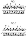
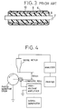
- Fig. 2 shows an example of a charging roll in which a foam layer 22 is formed of an insulating foam material, and includes axially opposite end portions 24, 24 which are made electrically conductive.
- the foam layer 22 is formed by impregnating the end portions 24 with a liquid including an electrically conductive powder or fiber, such as carbon black or carbon fiber, dispersed in water, and then drying the impregnated end portions 24.
- the material used for the conductive elastic layer 16 may be optimally selected from electrically conductive rubber compositions or conductive thermoplastic elastomers, which contain conductive powder or fiber, such as metal powder, carbon black or carbon fiber.
- the elastic layer 16 may also be formed of a hard resin if the layer 16 has such a small thickness as to be easily elastically deformed. In this case, however, it becomes difficult to ensure a sufficiently large contact area or width between the charging roll and the photosensitive drum, since even a relatively thin layer of the hard resin increases the hardness of the roll.
- the use of the hard resin is also disadvantageous since the thickness of the hard resin layer must be reduced to be as small as about 50 ⁇ m, making it difficult to form and handle the layer, or causing breakage or other problems.
- the thickness of the conductive elastic layer 16 as described above is desirably held in a range of 100 ⁇ m to 1200 ⁇ m. If the thickness of the elastic layer 16 is smaller than 100 ⁇ m, the elastic layer 16 is not able to sufficiently cover and eliminate cell defects of the foam layer 14, 22. As a result, recesses and the like tend to appear on the elastic layer 16 at its portions corresponding to the cell defects, resulting in poor smoothness of the surface of the roll. If the thickness of the elastic layer 16 exceeds 1200 ⁇ m, the effect of the foam layer 14, 22 for reducing noise is deteriorated.
- the shaft 12 is disposed at the center of a cylindrical metallic mold, and a relatively thin tube made of an electrically conductive elastic material, which gives the conductive elastic layer 16, is disposed coaxially with the center shaft 12. Then, a molding material which gives the foam body 14, 22 is injected under pressure into a cylindrical space between the shaft 12 and the elastic layer 16, and a foaming operation is effected to form the foam body 14, 22.
- the foam layer 14, 22 and conductive elastic layer 16, and the foam layer 14, 22 and center shaft 12 are fixed to each other with sufficiently high durability, only due to the pressure of the foam body 14, 22, without using an adhesive.
- the foam layer 14, 22 may be bonded to the elastic layer 14 and the shaft 12 as needed, by means of a suitable adhesive, without affecting the effect of the present invention.
- the elastic layer 16 When the resistance adjusting layer 18 is formed by coating on the outer surface of the conductive elastic layer 16, the elastic layer 16 may be swollen with a solvent of a coating liquid which provides the resistance adjusting layer 18. To avoid this, it is desirable to coat the conductive elastic layer 16 with an electrically conductive resin layer which is not swollen with the solvent, and then coat the resin layer with the resistance adjusting layer 18.
- the conductive resin layer has a thickness of several microns, and may be formed of a material having as a major component a nylon-based polymer or modified nylon, such as N-methoxymethylated nylon.
- the resistance adjusting layer 18 is preferably formed of a rubber containing epichlorohydrin, for example, and is formed by a known coating method, such as dipping.
- the thickness of this layer 18 is generally held in a range of about 50 ⁇ 500 ⁇ m, preferably, about 80 ⁇ 160 ⁇ m.
- the protective layer 20 having a thickness of microns is formed by coating on the outer surface of the resistance adjusting layer 18, so as to prevent the layer 18 from adhering to the photosensitive drum.
- This protective layer 20 may be formed of a material having as a major component a nylon-based polymer or modified nylon, such as N-methoxymethylated nylon.
- the foam layer 14 and electrically conductive elastic layer 16 are advantageously formed on the center shaft 12, in the manner which will be hereinafter described referring to Fig. 5.
- the shaft 12 is disposed at the center of a columnar cavity of a cylindrical metallic mold 30, and a pre-foam tube 34 which gives the foam layer 14 upon its foaming is disposed radially outwardly of the shaft 12.
- an elastic tube 36 which gives the conductive elastic layer 16 is disposed radially outwardly of the pre-foam tube 16.
- cap members 38, 38 are fitted on the axially opposite end portions of the metallic mold 30.
- the pre-foam tube 34 giving the foam layer 14 is formed of a suitably selected foam material, such as urethane foam, hydrin rubber chloroprene rubber, EPDM and Cl-EPDM.
- a suitably selected foam material such as urethane foam, hydrin rubber chloroprene rubber, EPDM and Cl-EPDM.
- the pre-foam tube 34 is formed by extrusion, for example, with a thickness which is determined depending upon the expansion ratio of the foam material that is related to the volume of the foam layer 14 to be formed.
- the pre-foam tube 34 used for the charging roll has a thickness of about 1.5mm.
- the elastic tube 36 which gives the conductive elastic layer 16 of the charging roll for example, is formed of a known elastic material selected from various rubber compositions, such as EPDM or polyamide elastomer, or thermoplastic elastomers.
- the elastic tube 16 having a suitable thickness is formed by extrusion, by using the selected elastic material.
- a multiplicity of minute grooves 32 are formed in an outer circumferential surface of the pre-foam tube 34, as shown in Fig. 7, such that the grooves 32 extend in an axial direction of the tube 34, desirably over the entire axial length of the tube 34.
- These grooves 32 may be formed by a suitable method, such as (1) mechanically processing or machining the outer circumferential surface of the pre-foam tube 14 which has been extruded, so as to provide the surface with the minute grooves 32, or (2) extruding the pre-foam tube 34 from an extrusion die having grooves, so that the extruded tube 34 is formed at its outer circumferential surface with the minute grooves 32.
- the minute grooves 32 generally extend in parallel with each other in the axial direction of the pre-foam tube 34 and are arranged over the entire circumference of the tube 34, the grooves 26 may be formed in helical fashion over the outer circumferential surface of the pre-foam tube 34.
- the grooves 32 are arranged in the circumferential direction of the pre-foam tube 32, at a pitch (W) of about 0.1 ⁇ 5mm, as shown in Fig. 8.
- This pitch is determined depending upon the outside diameter of the pre-foam tube 34.
- the pre-foam tube 34 having an outside diameter of about 10mm and used for forming the charging roll is formed with the grooves 32 that are arranged at a pitch of 0.1 ⁇ 1mm.
- the grooves 32 have an insufficient depth (D), the grooves 32 tend to be closed upon foaming of the pre-foam tube 34, and the air generated during the foaming operation cannot effectively escape through the grooves 32. Accordingly, it is desirable to determine the depth (D) and pitch (W) of the grooves 32 so that the ratio D/W is equal to or greater than 0.3.
- the grooves 32 are not limited to any particular shape, but may be formed in any shape provided the grooves 32 remain for a long time enough to allow air to escape through the grooves 34 during the foaming operation for the pre-foam tube 34.
- the grooves 32 may have a triangular shape in cross section, as shown in Fig. 9. In this case, too, the above- indicated relationship between the depth (D) and pitch (W) of the grooves 32 should be desirably satisfied.
- a multiplicity of minute grooves 42 are formed in an inner circumferential surface of the elastic tube 36, such that the grooves 42 extend in an axial direction of the tube 36, desirably over the entire axial length of the tube 36.
- These grooves 42 may be formed by a suitable method, such as (1) grinding with sandpaper the inner circumferential surface of the elastic tube 36 which has been extruded, in the axial direction of the tube 36, so as to roughen the inner circumferential surface, or (2) extruding the elastic tube 36 from an extrusion die having grooves, so that the extruded tube 36 is provided at its inner circumferential surface with the minute grooves 42. While the minute grooves 42 extend in parallel with each other in the axial direction of the elastic tube 36 and are arranged over the entire circumference of the tube 34, the grooves 42 may be formed in helical fashion over the inner circumferential surface of the elastic tube 36.
- the outer circumferential surface of the elastic tube 36 preferably has a surface roughness: Rz of not less than 15 ⁇ m, where Rz represents the ten-point mean roughness, that is, the average value of the absolute values of the heights of five highest profile peaks and the depths of five deepest profile valleys within a sampling length. Since the surface smoothness of the roll is deteriorated if the surface roughness Rz is too high, the surface roughness Rz is generally controlled to be not greater than 50 ⁇ m, though the optimum roughness is depending upon the material, thickness and other factors of the elastic tube 36.
- the grooves 42 are arranged in the circumferential direction of the elastic tube 36, preferably at a pitch of about 0.05 ⁇ 1mm.
- pre-foam tube 34 and elastic tube 36 obtained by the first or second preferred method as described above are disposed coaxially with each other within the cavity of the metallic mold 30, in the manner as described above, the pre-foam tube 34 is subjected to a suitable foaming operation, such as heating, so as to provide a composite roll 40 as shown in Fig. 6.
- the composite roll 40 has the foam layer 14 and electrically conductive elastic layer 16 which are laminated on each other and formed integrally on the center shaft 12.
- air generated during the foaming operation can effectively escape from the axial end portions of the pre-foam tube 34 toward the outside of the roll, through the grooves 32 formed in the outer circumferential surface of the tube 34.
- such air can effectively escape outwards from the axial end portions of the elastic tube 36, through the grooves 42 formed in the inner circumferential surface of the elastic tube 36. Therefore, the air does not remain in the interior of the roll, thereby favorably avoiding voids which may otherwise appear between the foam layer 14 and elastic layer 16. Consequently, the composite roll 40 exhibits excellent surface smoothness.
- the above-described two preferred methods are not only employed for producing the charging roll constructed according to the present invention, but may be employed for producing any other kind of roll, such as an image developing roll, image transfer roll, cleaning roll or pressure roll, used in electrophotographic copying machines or printers, for example, provided the roll is a composite roll having a foam layer and a solid elastic layer superposed on the foam layer.
- a polyol mixture was initially prepared by mixing together the following ingredients: polyether polyol ("FA7030” available from Sanyo Chemical Industries, Ltd., Japan) 100 parts by weight H 2 O 1 part by weight aqueous solution of fatty acid sulfonate ("additive SV” available from Sumitomo Bayer Urethane K.K., Japan) 1 part by weight silicone foaming agent ("SRX274C” available from Toray Silicone K.K., Japan) 2 parts by weight triethanolamine 1.5 parts by weight N,N'-dimethylbenzylamine (catalyst) ("Kaorizer No. 20" available from Kao Corporation, Japan) 2 parts by weight triethylenediamine (catalyst) ("Dabco33 LV” available from Mitsui Air Products K.K., Japan) 1 part by weight
- the thus prepared polyol mixture was mixed with isocyanate ("Sumidule T-80" available from Sumitomo Bayer Urethane, K.K., Japan), in a proportion of 5.3:1.0, just before the mixture was injected into a mold.
- isocyanate Sudule T-80 available from Sumitomo Bayer Urethane, K.K., Japan
- ethylene-propylene rubber 100 parts by weight ketjenblack 40 parts by weight naphthenic oil 20 parts by weight
- N-methoxymethylated nylon 100 parts by weight was dissolved in a mixture of methanol and water, and then 15 parts by weight of ketjenblack was added to the solution thus obtained and dispersed by a beads type disperser.
- N-methoxymethylated nylon 100 parts by weight was dissolved in a mixture of methanol and water, and then 5 parts by weight of ketjenblack was added to the solution thus obtained and dispersed by a beads type disperser.
- the material (8) for forming the resistance adjusting layer as indicated above was applied by dipping to the outer surface of the conductive elastic layer to form an 80 ⁇ m-thickness layer, and then dried and subjected to heat treatment.
- the material (9) for forming the protective layer was applied by dipping to the thus formed resistance adjusting layer, to form a 5 ⁇ m-thickness layer, and then dried and heat-treated.
- the axially opposite end portions of the foam layer were impregnated with a liquid including carbon black dispersed in water, and then dried.
- the end portions of the foam layer were made electrically conductive, so as to permit the shaft and the conductive elastic layer to be electrically connected to each other. In this manner, there were obtained five specimens of charging roll constructed as shown in Fig. 2.
- the thus obtained charging rolls were tested by measuring the current value, the hardness of the roll, the noise level (sound level), and the surface roughness, and also evaluating the appearance of the roll. Further, the charging rolls were actually installed on printers, and the image producing capability of each of the printers using the respective charging rolls was evaluated. The results of the tests are indicated in TABLE 1 below.
- each of the charging rolls to be tested was held in pressed contact with a smooth metallic roll having a diameter of 30mm and rotating at 17rpm, with a 500gf load being applied to each of the opposite end portions of the center shaft of the roll.
- the current value was measured while a voltage of 500Vp-p (300 Hz) - 200V DC was applied to the shaft of the charging roll.
- the roll hardness was measured by using a SHORE A hardness meter, with a 1kg load being applied to the charging roll to be tested.
- the sound level was measured by a measuring device constructed as shown in Fig. 4, with a voltage of 2000Vp-p (500Hz) - 550V DC being applied to the shaft of the charging roll to be tested.
- the surface roughness was measured by the surface roughness meter named "SURFCOM” manufactured by Tokyo Seimitsu Co., Ltd, Japan.
- Three elastic tubes made of the electrically conductive polyester elastomer (5) as indicated above were produced by an extruder, such that the tubes had an outside diameter of 12mm, and respective thicknesses as indicated in TABLE 2 below. These elastic tubes were used to provide three specimens of charging rolls as Examples 5, 6 and Comparative Example 2. Each of the specimens were produced in the same manner as Example 1, wherein the foam layer and electrically conductive elastic layer were formed on the outer surface of the center shaft, and the resistance adjusting layer and protective layer were further formed on the conductive elastic layer. The shaft and the conductive elastic layer were electrically connected to each other in the same manner as in Example 1, so as to provide the intended charging roll as shown in Fig. 2.
- Example 2 The same measurements and evaluation as employed for Example 1 were effected on the charging rolls thus obtained, and the results thereof are indicated in TABLE 2 below. It will be apparent from the results that the charging rolls of Examples 5 and 6 caused significantly reduced noise, and exhibited excellent image producing capability. On the other hand, the charging roll of Comparative Example 2 having a 80 ⁇ m-thickness conductive elastic layer was not able to sufficiently cover and eliminate recesses due to cell defects of the foam layer, and the appearance of the roll was accordingly deteriorated, resulting in increased roughness of the roll surface and poor image producing capability.
- Two pre-foam tubes which give respective foam layers were prepared by an extruder, the tubes being formed of the electrically conductive hydrin rubber (2) as indicated above.
- two elastomer tubes were prepared by extrusion, using the electrically conductive polyester elastomer (5) and electrically conductive polyamide elastomer (6) as indicated above, respectively.
- These elastomer tubes which give respective conductive elastic layers had an outside diameter of 12mm and the thickness as indicated in TABLE 3 below.
- Each of the pre-foam conductive hydrin rubber tubes and the corresponding conductive elastomer tube were disposed coaxially with each other within a cylindrical metallic mold, with a 6mm-diameter center shaft (core) being disposed at the center of the mold.
- the tubes and shaft in the mold were heated by an oven, to achieve foaming and vulcanization of the tubes, so that the foam body and the conductive elastic layer were formed on the outer surface of the shaft. Further, a resistance adjusting layer and a protective layer were formed by dipping on the outer circumferential surface of each conductive elastic layer, in the same manner as Example 1, so as to provide two specimens (Examples 7, 8) of charging rolls as shown in Fig. 1.
- Example 1 The same measurements and evaluation as employed for Example 1 were effected on the charging rolls thus obtained, and the results thereof are indicated in TABLE 3 below. It will be apparent from the results that the charging rolls of Examples 7 and 8 caused comparatively small noise, and exhibited excellent image producing capability.
- pre-foam tubes were initially prepared by an extruder, using the electrically conductive hydrin rubber (2) as indicated above.
- Each of the pre-foam tubes and a 6mm-diameter center shaft (core) were disposed coaxially with each other within a cylindrical metallic mold, and heated by an oven, to achieve foaming and vulcanization of the tube, so that a foam layer having a thickness of 3mm was formed on the outer surface of the shaft.
- three specimens of charging rolls were produced as Comparative Examples 3, 4 and 5 in which the respective foam layers had different expansion ratios.
- the foam layer of each charging roll was coated by dipping with a 10 ⁇ m-thickness layer of the electrically conductive N-methoxymethylated nylon (7) as indicated above, which was then dried and heat-treated. Further, the resistance adjusting layer and a protective layer were formed by dipping on the above coating layer, in the same manner as Example 1, so as to provide the intended charging roll.
- Example 4 The same measurements and evaluation as employed for Example 1 were conducted on the charging rolls thus obtained, and the results thereof are indicated in TABLE 4 below.
- Comparative Examples 3 and 4 the expansion ratio of the foam layer was made relatively high so as to reduce the hardness of the charging roll. In this case, the noise can be effectively reduced, but the appearance of the roll is deteriorated with creases appearing on the coating layer due to shrinking thereof, resulting in increased roughness of the roll surface and poor image producing capability.
- Comparative Example 5 the expansion ratio of the foam layer was made relatively low so as to avoid the creases of the coating layer. In this case, however, the roll has a relatively high hardness and the noise made by the roll is undesirably increased.
- a 6mm-thickness center shaft (core) and the electrically conductive rubber (solid) (3) as indicated above were disposed in a metallic mold, and were heated by press, so that a 3mm-thickness conductive rubber layer was formed on the outer circumferential surface of the shaft. Then, the surface of the conductive rubber layer was made smooth by grinding, and was coated by dipping with a 10 ⁇ m-thickness layer of the electrically conductive N-methoxymethylated nylon (7) as indicated above, which was then dried and heat-treated. Then, a resistance adjusting layer and a protective layer were further formed by dipping on the coating layer, in the same manner as Example 1, so as to provide an intended charging roll as Comparative Example 6.
- Example 2 The same measurements and evaluation as employed for Example 1 were effected on the thus obtained charging roll, and the results thereof are indicated in TABLE 4 above. It will be understood from the results that the Shore A hardness of the charging roll was increased to as high as 64 and the roll made a comparatively large noise.
- hydrin rubber having a composition as indicated below was prepared, and pre-foam tubes having an inside diameter of 7.5mm and an outside diameter of 10mm were produced by extruding the thus prepared hydrin rubber through grooved extrusion dies, so that a multiplicity of minute grooves were formed in the outer circumferential surface of each pre-foam tube, in the axial direction of the tube.
- the number and depth of the grooves formed in the pre-foam tube are indicated in TABLE 5 below.
- EPDM ethylene-propylene copolymer rubber
- polyamide elastomer each having a composition as indicated below
- elastic tubes having an inside diameter of 11.4mm and an outside diameter of 11.8mm were formed by extrusion.
- Composition of EPDM EPDM 100 parts by weight ZnO 5 parts by weight stearic acid 1 part by weight processed oil 30 parts by weight electrically conductive carbon 33 parts by weight peroxide 3.5 parts by weight cross linking agent 3 parts by weight
- Composition of Polyamide Elastomer polyamide elastomer available from Toray Industries Inc., Japan Trade name: Pebax
- Pebax Polyamide Elastomer polyamide elastomer
- a cylindrical metallic mold having an inside diameter of 12mm was prepared, and a 6mm-diameter shaft (core) was disposed at the center of a cavity of the mold. Then, the pre-foam tube and elastic tube of each specimen were disposed coaxially with each other, and the opposite axial ends of the metallic mold were closed by respective cap members. Thereafter, the cylindrical metallic mold was put into an oven, and the pre-foam and elastic tubes were heated at 160°C for 40 minutes, so as to foam the pre-foam tube. In this manner, three examples (Examples 9, 10 and 11) of composite rolls each having a foam layer formed integrally with a solid elastic layer were prepared. As Comparative Example 7, there was prepared a composite roll formed from a pre-foam tube having no grooves, and the elastic tube as described above.
- hydrin rubber having a composition as indicated below was prepared, and pre-foam tubes having an inside diameter of 8 mm and an outside diameter of 10mm were produced by extrusion.
- Composition of Hydrin Rubber hydrin rubber 100 parts by weight carbon black 40 parts by weight softening agent 10 parts by weight vulcanizing agent 1.5 parts by weight foaming agent 5 parts by weight foaming aid 5 parts by weight
- elastic tubes each having an inside diameter of 11.4mm and an outside diameter of 11.8mm were formed by extrusion.
- a grooved extrusion spindle was used for extruding each of the elastic tubes, so that minute grooves were formed in the inner circumferential surface of the elastic tube, and so that the inner circumferential surface had a surface roughness (Rz) as indicated in TABLE 6 below.
- Rz surface roughness
- the inner circumferential surface of each of the elastic tubes was ground with various kinds of sand paper, in the axial direction of the tube, after extrusion of these elastic tubes.
- the inner circumferential surface of the relevant elastic tube was formed with minute grooves, to provide a surface roughness (Rz) as indicated in TABLE 6 below.
- Composition of Polyamide Elastomer polyamide elastomer available from Toray Industries, Ltd., Japan Trade name: Pebax
- electrically conductive carbon 30 parts by weight
- a cylindrical metallic mold having an inside diameter of 12mm was prepared, and a 6mm-diameter shaft (core) was disposed at the center of a cavity of the mold. Then, the pre-foam tube and elastic tube of each example were disposed coaxially with each other, and the opposite axial ends of the metallic mold were closed by respective cap members. Thereafter, the cylindrical metallic mold was put into an oven, and the pre-foam and elastic tubes were heated at 160°C for 40 minutes, so as to foam the pre-foam tube. In this manner, ten specimens of composite rolls each having a foam layer formed integrally with a solid elastic layer were prepared. As Comparative Example 8, there was prepared a composite roll formed from the pre-foam tube as described above, and an elastic tube having no grooves.
- a charging roll which includes a center shaft (12), a foam layer (14, 22) formed on an outer circumferential surface of the center shaft, an electrically conductive elastic layer (16) formed on an outer surface of the foam layer, and a resistance adjusting layer (18) and a protective layer (20) formed by coating on an outer surface of the electrically conductive elastic layer.
- the foam layer consists of an electrically conductive foam body or a foam body a part of which is made electrically conductive.
- a method of producing a composite roll, such as the above charging roll which includes a foam layer formed on a shaft, and a solid elastic layer formed on the foam layer. This method includes the step of forming multiple minute grooves (32, 42) in an outer circumferential surface of a pre-foam tube (34) which gives the foam layer, or an inner circumferential surface of an elastic tube (36) which gives the solid elastic layer.
Landscapes
- Physics & Mathematics (AREA)
- General Physics & Mathematics (AREA)
- Engineering & Computer Science (AREA)
- General Engineering & Computer Science (AREA)
- Plasma & Fusion (AREA)
- Mechanical Engineering (AREA)
- Electrostatic Charge, Transfer And Separation In Electrography (AREA)
Applications Claiming Priority (10)
| Application Number | Priority Date | Filing Date | Title |
|---|---|---|---|
| JP354597/92 | 1992-12-16 | ||
| JP4354597A JP2740998B2 (ja) | 1992-12-16 | 1992-12-16 | 帯電ロールの製造方法 |
| JP35459792 | 1992-12-16 | ||
| JP180621/93 | 1993-06-24 | ||
| JP180620/93 | 1993-06-24 | ||
| JP18062193 | 1993-06-24 | ||
| JP18062093 | 1993-06-24 | ||
| JP5180621A JP2651987B2 (ja) | 1993-06-24 | 1993-06-24 | 複合ロールの製造方法 |
| JP18062093A JP3211494B2 (ja) | 1993-06-24 | 1993-06-24 | 複合ロールの製造方法 |
| EP19930118385 EP0602395B1 (fr) | 1992-12-16 | 1993-11-12 | Procédé de production d'un rouleau lequel comporte un corps en mousse |
Related Parent Applications (2)
| Application Number | Title | Priority Date | Filing Date |
|---|---|---|---|
| EP19930118385 Division EP0602395B1 (fr) | 1992-12-16 | 1993-11-12 | Procédé de production d'un rouleau lequel comporte un corps en mousse |
| EP93118385.9 Division | 1993-11-12 |
Publications (2)
| Publication Number | Publication Date |
|---|---|
| EP0779562A1 true EP0779562A1 (fr) | 1997-06-18 |
| EP0779562B1 EP0779562B1 (fr) | 2000-06-28 |
Family
ID=27324876
Family Applications (2)
| Application Number | Title | Priority Date | Filing Date |
|---|---|---|---|
| EP19970100552 Expired - Lifetime EP0779562B1 (fr) | 1992-12-16 | 1993-11-12 | Rouleau comportant un corps en mousse et procédé de production du rouleau |
| EP19930118385 Expired - Lifetime EP0602395B1 (fr) | 1992-12-16 | 1993-11-12 | Procédé de production d'un rouleau lequel comporte un corps en mousse |
Family Applications After (1)
| Application Number | Title | Priority Date | Filing Date |
|---|---|---|---|
| EP19930118385 Expired - Lifetime EP0602395B1 (fr) | 1992-12-16 | 1993-11-12 | Procédé de production d'un rouleau lequel comporte un corps en mousse |
Country Status (3)
| Country | Link |
|---|---|
| US (1) | US6096395A (fr) |
| EP (2) | EP0779562B1 (fr) |
| DE (2) | DE69328939T2 (fr) |
Cited By (4)
| Publication number | Priority date | Publication date | Assignee | Title |
|---|---|---|---|---|
| WO2000004297A1 (fr) * | 1998-07-18 | 2000-01-27 | Felix Böttcher Gmbh & Co. | Rouleaux et procede de production de ces rouleaux |
| EP1400866A1 (fr) * | 2002-09-20 | 2004-03-24 | Tokai Rubber Industries, Ltd. | Rouleau conducteur |
| EP1506599B1 (fr) * | 2002-05-16 | 2007-07-11 | Homac Mfg. Company | Connecteur electrique comprenant un materiau thermoplastique elastomere et procedes associes |
| EP1674936A3 (fr) * | 2004-12-02 | 2008-10-22 | E.I. Du Pont De Nemours And Company | Procédé et appareil de développement thermique d'un élément graphique avec surface du support texturée |
Families Citing this family (19)
| Publication number | Priority date | Publication date | Assignee | Title |
|---|---|---|---|---|
| EP0840176B1 (fr) * | 1993-07-30 | 2001-10-31 | Canon Kabushiki Kaisha | Membre de charge, dispositif de charge et cartouche de traitement montée de manière amovible dans un appareil de formation d'images |
| JP3575054B2 (ja) * | 1994-04-22 | 2004-10-06 | 東海ゴム工業株式会社 | 導電性ロールの製造方法 |
| EP0708381B1 (fr) * | 1994-10-18 | 2002-01-30 | Canon Kabushiki Kaisha | Membre de charge, procédé de fabrication d'un membre de charge, et unité de traitement avec un tel membre de charge |
| EP0708382B1 (fr) | 1994-10-18 | 2002-01-30 | Canon Kabushiki Kaisha | Procédé de refabrication d'un membre de charge |
| FI111025B (fi) * | 1997-05-30 | 2003-05-15 | Metso Paper Inc | Kestomuovipinnoitteinen tela, menetelmä telan valmistamiseksi, kestomuovipinnoitekoostumus, kalanterointimenetelmä keksinnön mukaisia kestomuovipinnotteisia teloja käyttäen sekä telojen avulla valmistettu paperi/kartonki |
| JP2000088677A (ja) * | 1998-09-09 | 2000-03-31 | Kinugawa Rubber Ind Co Ltd | 感圧センサ |
| JP2000137369A (ja) * | 1998-10-30 | 2000-05-16 | Tokai Rubber Ind Ltd | 帯電ロール |
| DE19925421A1 (de) * | 1999-06-02 | 2000-12-07 | Voith Sulzer Papiertech Patent | Elastische Walze und Verfahren zum Herstellen einer solchen |
| AU2001280122A1 (en) * | 2000-08-25 | 2002-03-04 | Bridgestone Corporation | Transfer roll and image-forming apparatus |
| JP3719647B2 (ja) * | 2000-09-25 | 2005-11-24 | 株式会社リコー | 帯電ローラ、帯電装置、担持体ユニット、画像形成装置及び帯電ローラの製造方法 |
| JP2004191561A (ja) * | 2002-12-10 | 2004-07-08 | Bridgestone Corp | 現像ローラ及び画像形成装置 |
| US8620187B2 (en) * | 2011-06-28 | 2013-12-31 | Xerox Corporation | Surface coatings for the bias charging roller |
| EP3413136B1 (fr) * | 2016-02-01 | 2021-11-10 | Bridgestone Corporation | Rouleau de charge |
| JP2019164266A (ja) * | 2018-03-20 | 2019-09-26 | 富士ゼロックス株式会社 | 定着用加圧部材、定着装置及び画像形成装置 |
| WO2020022451A1 (fr) * | 2018-07-27 | 2020-01-30 | 株式会社大阪ソーダ | Composition de matériau d'absorption acoustique |
| JP7146682B2 (ja) * | 2019-03-27 | 2022-10-04 | 住友理工株式会社 | 電子写真機器用現像ロールおよび電子写真機器用現像ロールの製造方法 |
| JP7499332B2 (ja) * | 2020-07-01 | 2024-06-13 | Nok株式会社 | 現像ロール |
| JP7621041B2 (ja) * | 2021-02-19 | 2025-01-24 | 住友理工株式会社 | 電子写真機器用帯電ロール |
| US11891252B1 (en) * | 2023-01-03 | 2024-02-06 | Dematic Corp. | Sound attenuated conveyor roller assembly |
Citations (8)
| Publication number | Priority date | Publication date | Assignee | Title |
|---|---|---|---|---|
| EP0210871A2 (fr) * | 1985-08-02 | 1987-02-04 | Showa Electric Wire & Cable Co.,Ltd. | Rouleau recouvert de caoutchouc ou de plastique, méthode et appareil en vue de sa fabrication |
| EP0323252A2 (fr) * | 1987-12-29 | 1989-07-05 | Kabushiki Kaisha Toshiba | Appareil pour procédé électrophotographique |
| EP0329366A1 (fr) * | 1988-02-19 | 1989-08-23 | Canon Kabushiki Kaisha | Elément pour charger |
| JPH02202430A (ja) * | 1989-01-31 | 1990-08-10 | Tokai Rubber Ind Ltd | 半導電性ロールの製法 |
| US4956211A (en) * | 1988-12-20 | 1990-09-11 | Nitto Kogyo Co., Ltd. | Elastic roller and a process for manufacturing the same |
| JPH04143769A (ja) * | 1990-10-05 | 1992-05-18 | Seiko Epson Corp | 弾性ローラー |
| JPH04216834A (ja) * | 1990-12-17 | 1992-08-06 | Bridgestone Corp | ポリウレタンフォーム成形品の製造方法 |
| EP0554114A2 (fr) * | 1992-01-30 | 1993-08-04 | Canon Kabushiki Kaisha | Membre de charge, dispositif de charge, cartouche de traitement et appareil de formation d'images |
Family Cites Families (9)
| Publication number | Priority date | Publication date | Assignee | Title |
|---|---|---|---|---|
| US3942888A (en) * | 1975-02-06 | 1976-03-09 | Xerox Corporation | Stepped transfer roller |
| US5103262A (en) * | 1980-06-25 | 1992-04-07 | Semiconductor Energy Laboratory Co., Ltd. | Printing member for electrostatic photocopying |
| US4666780A (en) * | 1985-08-08 | 1987-05-19 | Minnesota Mining And Manufacturing Company | Dielectric coating for recording member |
| US4807341A (en) * | 1987-10-13 | 1989-02-28 | Eastman Kodak Company | Toner fusing roll covered with crosslinked elastomeric siloxane copolymer containing diphenylsiloxane recurring units and method of preparation |
| US4970559A (en) * | 1987-11-10 | 1990-11-13 | Canon Kabushiki Kaisha | Organic polymer material having antistatic property, elastic revolution body and fixing device using the same |
| US5168313A (en) * | 1988-04-28 | 1992-12-01 | Kabushiki Kaisha Toshiba | Toner image transfer method and device for electrophotographic printing apparatus |
| US5075189A (en) * | 1990-01-09 | 1991-12-24 | Konica Corporation | Electrophotographic photoreceptor comprising an undercoat layer containing a polyamide copolymer |
| JP3068121B2 (ja) * | 1991-03-22 | 2000-07-24 | セイコーエプソン株式会社 | 現像装置 |
| US5312662A (en) * | 1991-12-18 | 1994-05-17 | Tokai Rubber Industries, Ltd. | Conductive roll |
-
1993
- 1993-11-10 US US08/149,815 patent/US6096395A/en not_active Expired - Lifetime
- 1993-11-12 DE DE69328939T patent/DE69328939T2/de not_active Expired - Fee Related
- 1993-11-12 EP EP19970100552 patent/EP0779562B1/fr not_active Expired - Lifetime
- 1993-11-12 DE DE69317864T patent/DE69317864T2/de not_active Expired - Fee Related
- 1993-11-12 EP EP19930118385 patent/EP0602395B1/fr not_active Expired - Lifetime
Patent Citations (8)
| Publication number | Priority date | Publication date | Assignee | Title |
|---|---|---|---|---|
| EP0210871A2 (fr) * | 1985-08-02 | 1987-02-04 | Showa Electric Wire & Cable Co.,Ltd. | Rouleau recouvert de caoutchouc ou de plastique, méthode et appareil en vue de sa fabrication |
| EP0323252A2 (fr) * | 1987-12-29 | 1989-07-05 | Kabushiki Kaisha Toshiba | Appareil pour procédé électrophotographique |
| EP0329366A1 (fr) * | 1988-02-19 | 1989-08-23 | Canon Kabushiki Kaisha | Elément pour charger |
| US4956211A (en) * | 1988-12-20 | 1990-09-11 | Nitto Kogyo Co., Ltd. | Elastic roller and a process for manufacturing the same |
| JPH02202430A (ja) * | 1989-01-31 | 1990-08-10 | Tokai Rubber Ind Ltd | 半導電性ロールの製法 |
| JPH04143769A (ja) * | 1990-10-05 | 1992-05-18 | Seiko Epson Corp | 弾性ローラー |
| JPH04216834A (ja) * | 1990-12-17 | 1992-08-06 | Bridgestone Corp | ポリウレタンフォーム成形品の製造方法 |
| EP0554114A2 (fr) * | 1992-01-30 | 1993-08-04 | Canon Kabushiki Kaisha | Membre de charge, dispositif de charge, cartouche de traitement et appareil de formation d'images |
Non-Patent Citations (3)
| Title |
|---|
| DATABASE WPI Week 9038, Derwent World Patents Index; AN 90-286911, XP002028282 * |
| PATENT ABSTRACTS OF JAPAN vol. 16, no. 424 (P - 1415) 7 September 1992 (1992-09-07) * |
| PATENT ABSTRACTS OF JAPAN vol. 16, no. 556 (C - 1007) 26 November 1992 (1992-11-26) * |
Cited By (5)
| Publication number | Priority date | Publication date | Assignee | Title |
|---|---|---|---|---|
| WO2000004297A1 (fr) * | 1998-07-18 | 2000-01-27 | Felix Böttcher Gmbh & Co. | Rouleaux et procede de production de ces rouleaux |
| EP1506599B1 (fr) * | 2002-05-16 | 2007-07-11 | Homac Mfg. Company | Connecteur electrique comprenant un materiau thermoplastique elastomere et procedes associes |
| EP1400866A1 (fr) * | 2002-09-20 | 2004-03-24 | Tokai Rubber Industries, Ltd. | Rouleau conducteur |
| US6908419B2 (en) | 2002-09-20 | 2005-06-21 | Tokai Rubber Industries, Ltd. | Conductive roll |
| EP1674936A3 (fr) * | 2004-12-02 | 2008-10-22 | E.I. Du Pont De Nemours And Company | Procédé et appareil de développement thermique d'un élément graphique avec surface du support texturée |
Also Published As
| Publication number | Publication date |
|---|---|
| EP0602395A3 (fr) | 1995-05-24 |
| DE69328939D1 (de) | 2000-08-03 |
| DE69328939T2 (de) | 2000-11-30 |
| EP0779562B1 (fr) | 2000-06-28 |
| EP0602395A2 (fr) | 1994-06-22 |
| EP0602395B1 (fr) | 1998-04-08 |
| US6096395A (en) | 2000-08-01 |
| DE69317864T2 (de) | 1998-09-03 |
| DE69317864D1 (de) | 1998-05-14 |
Similar Documents
| Publication | Publication Date | Title |
|---|---|---|
| EP0779562B1 (fr) | Rouleau comportant un corps en mousse et procédé de production du rouleau | |
| US5753154A (en) | Method of producing a conductive roll | |
| US6149564A (en) | Toner supply roll including porous cylindrical polyurethane sponge structure having skin layer having openings and alternate protrusions and recesses, and method of producing the same | |
| EP0789285A2 (fr) | Rouleau de fourniture de toner ayant des ouvertures dans la couche superficielle, d'une structure cylindrique en éponge en polyréthane poreuse, et son procédé de fabrication | |
| EP2667258A1 (fr) | Rouleau de développement, dispositif de développement et dispositif de formation d'image | |
| JP3489321B2 (ja) | 帯電ロール | |
| US20130300017A1 (en) | Foamed elastic body, method of manufacturing the same, and conductive roll for electrophotographic machine | |
| US6190295B1 (en) | Charging roll whose resistance adjusting layer contains insulating particles dispersed therein | |
| US5878313A (en) | Developing roller and apparatus | |
| JPH09258523A (ja) | 帯電ロール | |
| JP2740998B2 (ja) | 帯電ロールの製造方法 | |
| JP4215155B2 (ja) | 導電性部材 | |
| JP3765431B2 (ja) | 半導電性シリコーンゴムロール | |
| JP2001310362A (ja) | ゴムローラの製造方法及びゴムローラ | |
| JPH10319678A (ja) | 導電性ゴムローラ | |
| JP3211494B2 (ja) | 複合ロールの製造方法 | |
| JP2004037650A (ja) | 帯電付与部材 | |
| JP2651987B2 (ja) | 複合ロールの製造方法 | |
| JP3950591B2 (ja) | ゴムローラおよびその製造方法 | |
| JP2001209236A (ja) | 帯電部材 | |
| JPH10104938A (ja) | 半導電性ロール | |
| JP2008209668A (ja) | 現像ロール | |
| JP2012118273A (ja) | 電子写真機器用スポンジロールおよび電子写真機器用スポンジロールの製造方法 | |
| JPH09329939A (ja) | 帯電ロールの製造方法 | |
| JPH11223980A (ja) | 導電性ローラーの製造方法 |
Legal Events
| Date | Code | Title | Description |
|---|---|---|---|
| PUAI | Public reference made under article 153(3) epc to a published international application that has entered the european phase |
Free format text: ORIGINAL CODE: 0009012 |
|
| AC | Divisional application: reference to earlier application |
Ref document number: 602395 Country of ref document: EP |
|
| AK | Designated contracting states |
Kind code of ref document: A1 Designated state(s): DE FR GB |
|
| 17P | Request for examination filed |
Effective date: 19970902 |
|
| GRAG | Despatch of communication of intention to grant |
Free format text: ORIGINAL CODE: EPIDOS AGRA |
|
| 17Q | First examination report despatched |
Effective date: 19991001 |
|
| GRAG | Despatch of communication of intention to grant |
Free format text: ORIGINAL CODE: EPIDOS AGRA |
|
| GRAG | Despatch of communication of intention to grant |
Free format text: ORIGINAL CODE: EPIDOS AGRA |
|
| GRAH | Despatch of communication of intention to grant a patent |
Free format text: ORIGINAL CODE: EPIDOS IGRA |
|
| GRAH | Despatch of communication of intention to grant a patent |
Free format text: ORIGINAL CODE: EPIDOS IGRA |
|
| GRAA | (expected) grant |
Free format text: ORIGINAL CODE: 0009210 |
|
| AC | Divisional application: reference to earlier application |
Ref document number: 602395 Country of ref document: EP |
|
| AK | Designated contracting states |
Kind code of ref document: B1 Designated state(s): DE FR GB |
|
| REF | Corresponds to: |
Ref document number: 69328939 Country of ref document: DE Date of ref document: 20000803 |
|
| ET | Fr: translation filed | ||
| PLBE | No opposition filed within time limit |
Free format text: ORIGINAL CODE: 0009261 |
|
| STAA | Information on the status of an ep patent application or granted ep patent |
Free format text: STATUS: NO OPPOSITION FILED WITHIN TIME LIMIT |
|
| 26N | No opposition filed | ||
| REG | Reference to a national code |
Ref country code: GB Ref legal event code: IF02 |
|
| PGFP | Annual fee paid to national office [announced via postgrant information from national office to epo] |
Ref country code: FR Payment date: 20031110 Year of fee payment: 11 |
|
| PGFP | Annual fee paid to national office [announced via postgrant information from national office to epo] |
Ref country code: GB Payment date: 20031112 Year of fee payment: 11 |
|
| PG25 | Lapsed in a contracting state [announced via postgrant information from national office to epo] |
Ref country code: GB Free format text: LAPSE BECAUSE OF NON-PAYMENT OF DUE FEES Effective date: 20041112 |
|
| GBPC | Gb: european patent ceased through non-payment of renewal fee |
Effective date: 20041112 |
|
| PG25 | Lapsed in a contracting state [announced via postgrant information from national office to epo] |
Ref country code: FR Free format text: LAPSE BECAUSE OF NON-PAYMENT OF DUE FEES Effective date: 20050729 |
|
| REG | Reference to a national code |
Ref country code: FR Ref legal event code: ST |
|
| PGFP | Annual fee paid to national office [announced via postgrant information from national office to epo] |
Ref country code: DE Payment date: 20071108 Year of fee payment: 15 |
|
| PG25 | Lapsed in a contracting state [announced via postgrant information from national office to epo] |
Ref country code: DE Free format text: LAPSE BECAUSE OF NON-PAYMENT OF DUE FEES Effective date: 20090603 |