EP0779596A1 - Digitaliseur et méthode - Google Patents
Digitaliseur et méthode Download PDFInfo
- Publication number
- EP0779596A1 EP0779596A1 EP96308910A EP96308910A EP0779596A1 EP 0779596 A1 EP0779596 A1 EP 0779596A1 EP 96308910 A EP96308910 A EP 96308910A EP 96308910 A EP96308910 A EP 96308910A EP 0779596 A1 EP0779596 A1 EP 0779596A1
- Authority
- EP
- European Patent Office
- Prior art keywords
- stylus
- sensors
- signal
- active area
- display screen
- Prior art date
- Legal status (The legal status is an assumption and is not a legal conclusion. Google has not performed a legal analysis and makes no representation as to the accuracy of the status listed.)
- Withdrawn
Links
Images

Classifications
-
- G—PHYSICS
- G06—COMPUTING OR CALCULATING; COUNTING
- G06F—ELECTRIC DIGITAL DATA PROCESSING
- G06F3/00—Input arrangements for transferring data to be processed into a form capable of being handled by the computer; Output arrangements for transferring data from processing unit to output unit, e.g. interface arrangements
- G06F3/01—Input arrangements or combined input and output arrangements for interaction between user and computer
- G06F3/03—Arrangements for converting the position or the displacement of a member into a coded form
- G06F3/041—Digitisers, e.g. for touch screens or touch pads, characterised by the transducing means
- G06F3/046—Digitisers, e.g. for touch screens or touch pads, characterised by the transducing means by electromagnetic means
-
- G—PHYSICS
- G06—COMPUTING OR CALCULATING; COUNTING
- G06F—ELECTRIC DIGITAL DATA PROCESSING
- G06F3/00—Input arrangements for transferring data to be processed into a form capable of being handled by the computer; Output arrangements for transferring data from processing unit to output unit, e.g. interface arrangements
- G06F3/01—Input arrangements or combined input and output arrangements for interaction between user and computer
- G06F3/03—Arrangements for converting the position or the displacement of a member into a coded form
- G06F3/033—Pointing devices displaced or positioned by the user, e.g. mice, trackballs, pens or joysticks; Accessories therefor
- G06F3/0354—Pointing devices displaced or positioned by the user, e.g. mice, trackballs, pens or joysticks; Accessories therefor with detection of two-dimensional [2D] relative movements between the device, or an operating part thereof, and a plane or surface, e.g. 2D mice, trackballs, pens or pucks
- G06F3/03545—Pens or stylus
-
- G—PHYSICS
- G06—COMPUTING OR CALCULATING; COUNTING
- G06F—ELECTRIC DIGITAL DATA PROCESSING
- G06F3/00—Input arrangements for transferring data to be processed into a form capable of being handled by the computer; Output arrangements for transferring data from processing unit to output unit, e.g. interface arrangements
- G06F3/01—Input arrangements or combined input and output arrangements for interaction between user and computer
- G06F3/03—Arrangements for converting the position or the displacement of a member into a coded form
- G06F3/033—Pointing devices displaced or positioned by the user, e.g. mice, trackballs, pens or joysticks; Accessories therefor
- G06F3/038—Control and interface arrangements therefor, e.g. drivers or device-embedded control circuitry
-
- G—PHYSICS
- G06—COMPUTING OR CALCULATING; COUNTING
- G06F—ELECTRIC DIGITAL DATA PROCESSING
- G06F3/00—Input arrangements for transferring data to be processed into a form capable of being handled by the computer; Output arrangements for transferring data from processing unit to output unit, e.g. interface arrangements
- G06F3/01—Input arrangements or combined input and output arrangements for interaction between user and computer
- G06F3/03—Arrangements for converting the position or the displacement of a member into a coded form
- G06F3/041—Digitisers, e.g. for touch screens or touch pads, characterised by the transducing means
- G06F3/0412—Digitisers structurally integrated in a display
-
- G—PHYSICS
- G06—COMPUTING OR CALCULATING; COUNTING
- G06F—ELECTRIC DIGITAL DATA PROCESSING
- G06F3/00—Input arrangements for transferring data to be processed into a form capable of being handled by the computer; Output arrangements for transferring data from processing unit to output unit, e.g. interface arrangements
- G06F3/01—Input arrangements or combined input and output arrangements for interaction between user and computer
- G06F3/03—Arrangements for converting the position or the displacement of a member into a coded form
- G06F3/041—Digitisers, e.g. for touch screens or touch pads, characterised by the transducing means
- G06F3/0416—Control or interface arrangements specially adapted for digitisers
-
- G—PHYSICS
- G06—COMPUTING OR CALCULATING; COUNTING
- G06F—ELECTRIC DIGITAL DATA PROCESSING
- G06F2203/00—Indexing scheme relating to G06F3/00 - G06F3/048
- G06F2203/038—Indexing scheme relating to G06F3/038
- G06F2203/0384—Wireless input, i.e. hardware and software details of wireless interface arrangements for pointing devices
Definitions
- the present invention relates to digitizer apparatus and method.
- Digitizers or digitizing tablets for use as data input devices for notebook or pen-based computers are known.
- Some prior art digitizing tablets utilize a transparent digitizing grid system which is typically disposed on a substrate such as glass positioned over the surface of a Liquid Crystal Display (LCD) screen, to sense the coordinate position of a stylus device that is moved across the grid system.
- LCD Liquid Crystal Display
- the user of such a prior art device must view the LCD display screen through the grid structure of the digitizing tablet. While the grid structure is typically of film thickness, the edges of the transparent conductive runs may still be seen to some slight degree at certain times and under certain conditions.
- CMOS complementary metal-oxide-semiconductor
- a magnetic shield is added to the lower side of the grid.
- the position of a stylus is determined based on the interaction between the grid coils and a coil mounted on the pen. Since the stylus and the grid are separated by the LCD display, the interaction between the stylus and grid is reduced and the accuracy of the system is also reduced.
- the grid and the shield add a significant thickness and weight to the digitizing tablet.
- the invention therefore seeks to provide a digitizing tablet having advantages over known such tablets.
- digitizer apparatus for an input/output display screen having a housing portion and including a plurality of sensors mounted within said housing portion and positioned so as to define a boundary surrounding an active area of the display screen and for receiving a signal transmitted from a stylus.
- a method of determining the location of a stylus relative to an active area of a display screen comprising the steps of transmitting a signal from the stylus which is electromagnetically coupled to a plurality of sensors positioned to define a boundary surrounding an active area of the display screen and determining the location based on the relative strength of the signals received at the sensors.
- the present invention may also provide a method of detecting the presence of a stylus relative to an active area of a display screen.
- the method includes the steps of providing a number of sensors which are positioned to define a boundary surrounding an active area of the display screen, and transmitting a signal from the stylus to the sensors wherein the signal is indicative of the presence of the stylus relative to the active area.
- the providing step includes the step of securing the plurality of sensors to a display screen housing.
- the providing step may further include the step of providing four sensors which are positioned to define a boundary surrounding an active area of the display screen.
- the providing four sensors step may include the step of positioning each sensor adjacent to a corner of the active area.
- the transmitting step may include the step of transmitting an electro-magnetic signal to the plurality of sensors, the electro-magnetic signal being indicative of the position of the stylus relative to the active area of the display screen.
- each sensor may include a coil, and each of the plurality of sensors is spaced apart from the active area.
- a digitizer for a pen-based computer having a display screen secured to a housing.
- the digitizer includes a number of sensors secured to the housing and positioned so as to define a boundary surrounding an active area of the display screen, and a stylus for transmitting a signal to the sensors wherein the signal is indicative of the presence of the stylus relative to the active area.
- the sensors can each include a coil.
- the apparatus also includes a controller for processing said signal received by said sensors.
- a separate channel may be provided for coupling each sensor to said controller, and the stylus may comprise a cordless stylus, or a tethered stylus.
- the apparatus is arranged such that said signal is an electro-magnetic signal indicative of the position of said stylus relative to said active area.
- a pen-based computer including a housing, a display screen secured to the housing and having an active area, a number of sensors secured to the housing and positioned so as to define a boundary surrounding an active area of the display screen, and a stylus for transmitting a signal to the sensors wherein the signal is indicative of the presence of the stylus relative to the active area.
- the present invention advantageously provides for a new and useful method for sensing a stylus with an electro-magnetic digitizer.
- the present invention provides an improved digitizer where an active area of a display screen does not contain sensor components.
- the present invention can provide a new and useful digitizer having sensors positioned in the corners of a display screen housing.
- the present invention can advantageously provide a new and useful digitizer which has the advantages of an electrostatic tablet being transparent, thin and not requiring any components above or below a display screen, and at the same time has the advantage of an electromagnetic digitizing tablet being insensitive to the presence of a user's hand.
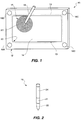
- a pen-based computer 10 such as a notebook computer, which incorporates features embodying the present invention.
- the computer 10 includes a base or frame 12 having a display screen 13 such as a Liquid Crystal Display (LCD) screen mounted thereto.
- An active area 14 of the display screen 13 conventionally displays text, data and/or graphics that may be input into the computer 10 from a pen or stylus 16.
- active area is a portion of the display screen 13 that includes addressable pixels for input and/or display purposes.
- the computer 10 also includes a number of sensors such as sensor coils 18 mounted to the frame 12.
- sensors such as sensor coils 18 mounted to the frame 12.
- the sensor coils 18a-18d are positioned so as to define a notional boundary 19 which encloses or surrounds the active area 14 of the display screen 13.
- the coils 18a-18d may be positioned at locations other than the corners of the frame 12.
- the sensor coils may be mounted to the frame at any location.
- the sensor coils 18a-18d receive an electro-magnetic signal 17 that is transmitted from the stylus 16 as described further below. It should be appreciated that the signal 17 radiates uniformly outwardly from the stylus 16 as shown in FIG. 1.
- the stylus 16, sensor coils 18a-18d and a controller 27 cooperate to define a digitizer for inputting data such as stylus position data, into the computer 10. That is, the digitizer facilitates the determination of the Cartesian coordinates (X, Y) which represent the position of the stylus 16 relative to an origin 20 which is arbitrarily positioned in the lower left-hand corner of the active area 14.
- the stylus 16 is a cordless-type stylus having at least an oscillator portion 21, transmitter portion 22 and battery portion 24 as shown in FIG. 2.
- the battery portion 24 supplies power to the oscillator portion 21 which then stimulates a coil (not shown) associated with the transmitter portion 22, to transmit the signal 17 from the stylus 16 to the sensor coils 18a-18d.
- the signal 17 is transmitted from the stylus 16 to the sensor coils 18a-18d by means of an electromagnetic coupling between the transmitter coil associated with the transmitter portion 22, and each of the sensor coils 18a-18d as shown by the electromagnetic lines of flux 26a, 26b in FIG. 3.
- the signal transmitted from the stylus 16 has a frequency of approximately 125KHz.
- the interaction between the stylus 16 and the respective sensor coils 18a-18d is similar to the interaction between the primary and secondary coils of a conventional transformer.
- the extent of electromagnetic coupling between the stylus 16 and the respective sensor coils 18a-18d is a function of the distance between the stylus 16 and the respective sensor coils 18a-18d.
- the closer the stylus 16 is to a particular sensor coil 18a-18d the greater the electromagnetic coupling between the stylus 16 and that sensor coil 18a-18d, and the greater the signal strength, i.e. amplitude of the signal received by that sensor coil 18a-18d.
- a controller 27 interfaces the digitizer to a CPU 30 of the computer 10.
- each of the sensor coils 18a-18d is operatively connected to the controller 27 through a separate channel 28a-28d, respectively.
- the controller 27 is operatively connected to the CPU 30 through a serial port 32.
- the transmitted signal from the stylus 16 induces a current into each of the four sensor coils 18a-18d.
- the induced currents are coupled to the controller 27 through the respective channels 28a-28d.
- the controller 27 converts the induced currents into voltage signals which are then amplified in a frequency selective manner prior to being converted to digital (binary) values indicative of the amplitude of the transmitted signal received at the particular sensor coils 18a-18d.
- the controller 27 determines the X, Y coordinate position of the stylus 16 based on a ratio of the signal amplitudes received at the sensor coils 18a-18d. More particularly, the signal amplitude received at each sensor coil 18a-18d is inversely proportional to the third power of the distance separating the stylus 16 from the respective sensor coils 18a-18d. Since the X, Y coordinate computations are based on a ratio of the received signal amplitudes, the computations are independent of the absolute signal amplitude received at each sensor coil 18a-18d.
- the controller 27 sends the calculated X, Y coordinate position of the stylus 16 to the CPU 30 for conventional processing via the serial port 32.
- the digitizer of the present invention exhibits the advantage of some known electrostatic digitizer tablets in that it is transparent, thin and does not require any components under the display screen 13, and at the same time has the advantage of other known electromagnetic digitizer tablets in that it is insensitive to the presence of a user's hand.
- the stylus 16 may also transmit digital information to the computer 10 through a repeating telemetry message which may be modulated onto the stylus 16 carrier signal via frequency modulation (FM).
- FM frequency modulation
- the telemetry information may be extracted from the transmitted signal and packaged along with the stylus X, Y coordinate data into a packet by the controller 27 for further processing by the CPU 30.
- the active area 14 of the display screen 13 has no sensor components associated therewith. i.e. no sensor components are positioned above or below the LCD screen, thus eliminating the problems associated with conductive grids used in the prior art.
- the sensor coils 18a-18d may be formed from conventional materials in a known manner to perform in accordance with a particular digitizer application, in terms of the shape and dimensions of the frame 12, and the controller 27 characteristics.
- the stylus 16 may be a tethered-type wherein the stylus 16 contains a transmitter portion which is powered by a separate driver unit that is coupled to the stylus via a supply cord.
Landscapes
- Engineering & Computer Science (AREA)
- General Engineering & Computer Science (AREA)
- Theoretical Computer Science (AREA)
- Physics & Mathematics (AREA)
- Human Computer Interaction (AREA)
- General Physics & Mathematics (AREA)
- Electromagnetism (AREA)
- Position Input By Displaying (AREA)
- User Interface Of Digital Computer (AREA)
Applications Claiming Priority (2)
| Application Number | Priority Date | Filing Date | Title |
|---|---|---|---|
| US08/573,211 US5768616A (en) | 1995-12-13 | 1995-12-13 | Apparatus for detecting electro-magnetic stylus signals by inducing current into a plurality of sensor coils using signals transmitted by the tranmitter coil of the stylus |
| US573211 | 1995-12-13 |
Publications (1)
| Publication Number | Publication Date |
|---|---|
| EP0779596A1 true EP0779596A1 (fr) | 1997-06-18 |
Family
ID=24291066
Family Applications (1)
| Application Number | Title | Priority Date | Filing Date |
|---|---|---|---|
| EP96308910A Withdrawn EP0779596A1 (fr) | 1995-12-13 | 1996-12-09 | Digitaliseur et méthode |
Country Status (4)
| Country | Link |
|---|---|
| US (1) | US5768616A (fr) |
| EP (1) | EP0779596A1 (fr) |
| JP (1) | JPH09179675A (fr) |
| KR (1) | KR970049357A (fr) |
Families Citing this family (14)
| Publication number | Priority date | Publication date | Assignee | Title |
|---|---|---|---|---|
| US5986646A (en) * | 1997-07-22 | 1999-11-16 | Ace Cad Enterprise Co., Ltd. | Method and apparatus for finding the location of a pointing instrument on a tablet |
| JP2002366292A (ja) * | 2001-06-13 | 2002-12-20 | Matsushita Electric Ind Co Ltd | 座標入力装置 |
| KR20060097962A (ko) * | 2005-03-08 | 2006-09-18 | 삼성전자주식회사 | 디스플레이장치 |
| US7996589B2 (en) * | 2005-04-22 | 2011-08-09 | Microsoft Corporation | Auto-suggest lists and handwritten input |
| JP4773330B2 (ja) * | 2006-12-25 | 2011-09-14 | 株式会社ワコム | ディスプレイ装置 |
| US20080169132A1 (en) * | 2007-01-03 | 2008-07-17 | Yao Ding | Multiple styli annotation system |
| USD609714S1 (en) * | 2007-03-22 | 2010-02-09 | Fujifilm Corporation | Electronic camera |
| US20090040185A1 (en) * | 2007-08-06 | 2009-02-12 | Huo-Lu Tsai | Antenna module for a display device that incorporates an electromagnetic digitizing tablet function |
| USD650800S1 (en) | 2010-12-01 | 2011-12-20 | Microsoft Corporation | Display screen with an icon |
| USD650793S1 (en) * | 2010-12-01 | 2011-12-20 | Microsoft Corporation | Display screen with an animated position indicator icon |
| US8922527B2 (en) | 2012-02-15 | 2014-12-30 | Cypress Semiconductor Corporation | Multi-purpose stylus antenna |
| KR102091710B1 (ko) * | 2012-08-28 | 2020-04-14 | 삼성전자주식회사 | 좌표 측정 장치 및 그 제어 방법 |
| FR2999742B1 (fr) * | 2012-12-13 | 2018-03-30 | Dav | Interface de commande tactile |
| WO2016088257A1 (fr) * | 2014-12-05 | 2016-06-09 | 昭 池谷 | Dispositif électronique et résonateur de type stylo |
Citations (6)
| Publication number | Priority date | Publication date | Assignee | Title |
|---|---|---|---|---|
| DE3737032C1 (en) * | 1987-10-31 | 1989-03-16 | Heidenhain Gmbh Dr Johannes | Absolute position-measuring device for measuring the relative position of two objects by means of ultrasonic waves |
| JPS6473414A (en) * | 1987-09-14 | 1989-03-17 | Wacom Co Ltd | Electronic blackboard device |
| WO1992002912A1 (fr) * | 1990-08-06 | 1992-02-20 | Schier J Alan | Appareil de detection |
| GB2258308A (en) * | 1991-07-27 | 1993-02-03 | Univ Nottingham | Inductive distance and movement gauge |
| WO1993009529A1 (fr) * | 1991-10-30 | 1993-05-13 | Calcomp Inc. | Numeriseur transparent a grille conductrice transparente |
| US5247261A (en) * | 1991-10-09 | 1993-09-21 | The Massachusetts Institute Of Technology | Method and apparatus for electromagnetic non-contact position measurement with respect to one or more axes |
Family Cites Families (12)
| Publication number | Priority date | Publication date | Assignee | Title |
|---|---|---|---|---|
| US4216352A (en) * | 1978-11-02 | 1980-08-05 | The Charles Stark Draper Laboratory, Inc. | Two coordinate position sensing systems |
| US4686332A (en) * | 1986-06-26 | 1987-08-11 | International Business Machines Corporation | Combined finger touch and stylus detection system for use on the viewing surface of a visual display device |
| US4716542A (en) * | 1985-09-26 | 1987-12-29 | Timberline Software Corporation | Method and apparatus for single source entry of analog and digital data into a computer |
| US4745565A (en) * | 1986-01-21 | 1988-05-17 | International Business Machines Corporation | Calibration of a force sensing type of data input device |
| US4777329A (en) * | 1987-08-24 | 1988-10-11 | Microfield Graphics, Inc. | Graphic input system |
| US4814552A (en) * | 1987-12-02 | 1989-03-21 | Xerox Corporation | Ultrasound position input device |
| US5007085A (en) * | 1988-10-28 | 1991-04-09 | International Business Machines Corporation | Remotely sensed personal stylus |
| JP2535626B2 (ja) * | 1989-10-27 | 1996-09-18 | キヤノン株式会社 | 座標入力装置 |
| JPH0792722B2 (ja) * | 1992-02-21 | 1995-10-09 | グラフテック株式会社 | デジタイザ |
| US5308936A (en) * | 1992-08-26 | 1994-05-03 | Mark S. Knighton | Ultrasonic pen-type data input device |
| US5466895A (en) * | 1994-01-07 | 1995-11-14 | Microtouch Systems, Inc. | Wear resistant improved tablet for a digitizer |
| US5543589A (en) * | 1994-05-23 | 1996-08-06 | International Business Machines Corporation | Touchpad with dual sensor that simplifies scanning |
-
1995
- 1995-12-13 US US08/573,211 patent/US5768616A/en not_active Expired - Lifetime
-
1996
- 1996-11-29 JP JP31900996A patent/JPH09179675A/ja active Pending
- 1996-12-04 KR KR1019960061707A patent/KR970049357A/ko not_active Ceased
- 1996-12-09 EP EP96308910A patent/EP0779596A1/fr not_active Withdrawn
Patent Citations (6)
| Publication number | Priority date | Publication date | Assignee | Title |
|---|---|---|---|---|
| JPS6473414A (en) * | 1987-09-14 | 1989-03-17 | Wacom Co Ltd | Electronic blackboard device |
| DE3737032C1 (en) * | 1987-10-31 | 1989-03-16 | Heidenhain Gmbh Dr Johannes | Absolute position-measuring device for measuring the relative position of two objects by means of ultrasonic waves |
| WO1992002912A1 (fr) * | 1990-08-06 | 1992-02-20 | Schier J Alan | Appareil de detection |
| GB2258308A (en) * | 1991-07-27 | 1993-02-03 | Univ Nottingham | Inductive distance and movement gauge |
| US5247261A (en) * | 1991-10-09 | 1993-09-21 | The Massachusetts Institute Of Technology | Method and apparatus for electromagnetic non-contact position measurement with respect to one or more axes |
| WO1993009529A1 (fr) * | 1991-10-30 | 1993-05-13 | Calcomp Inc. | Numeriseur transparent a grille conductrice transparente |
Non-Patent Citations (3)
| Title |
|---|
| "Ultrasonic Pen for Interactive Computing", RESEARCH DISCLOSURE, no. 259, November 1985 (1985-11-01), HAVANT GB, pages 25947, XP002027752 * |
| BIGOT S ET AL: "UTILISATION D'UNE ONDE PROGRESSIVE DE SURFACE POUR TABLEAU GRAPHIQUE DE GRANDES DIMENSIONS", REVUE DE PHYSIQUE APPLIQUEE, vol. 23, no. 7, July 1988 (1988-07-01), pages 1257 - 1263, XP000049756 * |
| PATENT ABSTRACTS OF JAPAN vol. 013, no. 291 (P - 893) 6 July 1989 (1989-07-06) * |
Also Published As
| Publication number | Publication date |
|---|---|
| US5768616A (en) | 1998-06-16 |
| JPH09179675A (ja) | 1997-07-11 |
| KR970049357A (ko) | 1997-07-29 |
Similar Documents
| Publication | Publication Date | Title |
|---|---|---|
| US5768616A (en) | Apparatus for detecting electro-magnetic stylus signals by inducing current into a plurality of sensor coils using signals transmitted by the tranmitter coil of the stylus | |
| US6133906A (en) | Display-integrated stylus detection system | |
| EP0680009A2 (fr) | Système d'entrée d'information angulaire | |
| EP0610262B1 (fr) | Numeriseur transparent a grille conductrice transparente | |
| US7113175B2 (en) | Methods and apparatus for supplying power to touch input devices in a touch sensing system | |
| EP0187372B1 (fr) | Dispositif pour la détection d'une position | |
| US8564553B2 (en) | Electronic stylus, capacitive touchpad module, and apparatus for touch input | |
| US5007085A (en) | Remotely sensed personal stylus | |
| US7268771B2 (en) | Panel display screen with touch control function | |
| EP0911754A2 (fr) | Dispositif d'affichage pour une tablette intelligente sensible au toucher | |
| EP1469383A1 (fr) | Dispositif d'affichage a effleurement comportant une couche d'induction electromagnetique integree | |
| JPH08314636A (ja) | 画像消去方法及びスタイラス型電子筆記システム | |
| US4523654A (en) | Electrographic system | |
| GB2139762A (en) | An input device and a method of inputting data to a computer system | |
| EP0923022A3 (fr) | Dispositif et tapis pour l'entrée de coordonnées, procédé de communication pour un tel dispositif | |
| US20090231299A1 (en) | Touch control display screen apparatus with a built-in electromagnetic induction layer of wire lattice | |
| KR100257963B1 (ko) | 디지타이징 패널을 디스플레이 장치와 정렬시키기 위한 방법및 장치 | |
| EP0602913A2 (fr) | Méthode d'utilisation de crayons d'entrée multiples dans un système à multiples ordinateurs | |
| US4897510A (en) | Coordinate inputting device including an electrode to reduce noise components | |
| EP1471411A1 (fr) | Tableau blanc electronique avec dispositif generateur d'induction a electro-aimant a membrane souple | |
| KR950004448B1 (ko) | 컴퓨터용 좌표위치 검출 입력장치 | |
| CN1164064A (zh) | 框式坐标定位仪 | |
| JPH10228345A (ja) | 電子ペン入力装置 | |
| US11995276B2 (en) | Touch sensitive structure and touch sensitive processing apparatus, method and electronic system thereof | |
| EP3936987A1 (fr) | Dispositif intelligent à double interface |
Legal Events
| Date | Code | Title | Description |
|---|---|---|---|
| PUAI | Public reference made under article 153(3) epc to a published international application that has entered the european phase |
Free format text: ORIGINAL CODE: 0009012 |
|
| AK | Designated contracting states |
Kind code of ref document: A1 Designated state(s): DE FR GB |
|
| 17P | Request for examination filed |
Effective date: 19970804 |
|
| RAP1 | Party data changed (applicant data changed or rights of an application transferred) |
Owner name: SYMBIOS, INC. |
|
| RAP1 | Party data changed (applicant data changed or rights of an application transferred) |
Owner name: LSI LOGIC CORPORATION |
|
| 17Q | First examination report despatched |
Effective date: 20010330 |
|
| STAA | Information on the status of an ep patent application or granted ep patent |
Free format text: STATUS: THE APPLICATION IS DEEMED TO BE WITHDRAWN |
|
| 18D | Application deemed to be withdrawn |
Effective date: 20010810 |