EP0780060B1 - Dispositif pour couper des tiges de cigarette - Google Patents
Dispositif pour couper des tiges de cigarette Download PDFInfo
- Publication number
- EP0780060B1 EP0780060B1 EP96120813A EP96120813A EP0780060B1 EP 0780060 B1 EP0780060 B1 EP 0780060B1 EP 96120813 A EP96120813 A EP 96120813A EP 96120813 A EP96120813 A EP 96120813A EP 0780060 B1 EP0780060 B1 EP 0780060B1
- Authority
- EP
- European Patent Office
- Prior art keywords
- cutting
- counterblade
- supporting body
- axis
- blade
- Prior art date
- Legal status (The legal status is an assumption and is not a legal conclusion. Google has not performed a legal analysis and makes no representation as to the accuracy of the status listed.)
- Expired - Lifetime
Links
- 238000005520 cutting process Methods 0.000 title claims description 53
- 235000019504 cigarettes Nutrition 0.000 title claims description 31
- 230000002093 peripheral effect Effects 0.000 claims description 2
- 230000000712 assembly Effects 0.000 description 6
- 238000000429 assembly Methods 0.000 description 6
- 238000004519 manufacturing process Methods 0.000 description 3
Images


Classifications
-
- B—PERFORMING OPERATIONS; TRANSPORTING
- B26—HAND CUTTING TOOLS; CUTTING; SEVERING
- B26D—CUTTING; DETAILS COMMON TO MACHINES FOR PERFORATING, PUNCHING, CUTTING-OUT, STAMPING-OUT OR SEVERING
- B26D1/00—Cutting through work characterised by the nature or movement of the cutting member or particular materials not otherwise provided for; Apparatus or machines therefor; Cutting members therefor
- B26D1/01—Cutting through work characterised by the nature or movement of the cutting member or particular materials not otherwise provided for; Apparatus or machines therefor; Cutting members therefor involving a cutting member which does not travel with the work
- B26D1/12—Cutting through work characterised by the nature or movement of the cutting member or particular materials not otherwise provided for; Apparatus or machines therefor; Cutting members therefor involving a cutting member which does not travel with the work having a cutting member moving about an axis
- B26D1/14—Cutting through work characterised by the nature or movement of the cutting member or particular materials not otherwise provided for; Apparatus or machines therefor; Cutting members therefor involving a cutting member which does not travel with the work having a cutting member moving about an axis with a circular cutting member, e.g. disc cutter
- B26D1/157—Cutting through work characterised by the nature or movement of the cutting member or particular materials not otherwise provided for; Apparatus or machines therefor; Cutting members therefor involving a cutting member which does not travel with the work having a cutting member moving about an axis with a circular cutting member, e.g. disc cutter rotating about a movable axis
- B26D1/16—Cutting through work characterised by the nature or movement of the cutting member or particular materials not otherwise provided for; Apparatus or machines therefor; Cutting members therefor involving a cutting member which does not travel with the work having a cutting member moving about an axis with a circular cutting member, e.g. disc cutter rotating about a movable axis mounted on a movable arm or the like
-
- A—HUMAN NECESSITIES
- A24—TOBACCO; CIGARS; CIGARETTES; SIMULATED SMOKING DEVICES; SMOKERS' REQUISITES
- A24C—MACHINES FOR MAKING CIGARS OR CIGARETTES
- A24C5/00—Making cigarettes; Making tipping materials for, or attaching filters or mouthpieces to, cigars or cigarettes
- A24C5/14—Machines of the continuous-rod type
- A24C5/28—Cutting-off the tobacco rod
-
- Y—GENERAL TAGGING OF NEW TECHNOLOGICAL DEVELOPMENTS; GENERAL TAGGING OF CROSS-SECTIONAL TECHNOLOGIES SPANNING OVER SEVERAL SECTIONS OF THE IPC; TECHNICAL SUBJECTS COVERED BY FORMER USPC CROSS-REFERENCE ART COLLECTIONS [XRACs] AND DIGESTS
- Y10—TECHNICAL SUBJECTS COVERED BY FORMER USPC
- Y10T—TECHNICAL SUBJECTS COVERED BY FORMER US CLASSIFICATION
- Y10T83/00—Cutting
- Y10T83/465—Cutting motion of tool has component in direction of moving work
- Y10T83/4734—Flying support or guide for work
-
- Y—GENERAL TAGGING OF NEW TECHNOLOGICAL DEVELOPMENTS; GENERAL TAGGING OF CROSS-SECTIONAL TECHNOLOGIES SPANNING OVER SEVERAL SECTIONS OF THE IPC; TECHNICAL SUBJECTS COVERED BY FORMER USPC CROSS-REFERENCE ART COLLECTIONS [XRACs] AND DIGESTS
- Y10—TECHNICAL SUBJECTS COVERED BY FORMER USPC
- Y10T—TECHNICAL SUBJECTS COVERED BY FORMER US CLASSIFICATION
- Y10T83/00—Cutting
- Y10T83/465—Cutting motion of tool has component in direction of moving work
- Y10T83/4766—Orbital motion of cutting blade
- Y10T83/4795—Rotary tool
- Y10T83/4818—Interconnected work feeder and tool driver
-
- Y—GENERAL TAGGING OF NEW TECHNOLOGICAL DEVELOPMENTS; GENERAL TAGGING OF CROSS-SECTIONAL TECHNOLOGIES SPANNING OVER SEVERAL SECTIONS OF THE IPC; TECHNICAL SUBJECTS COVERED BY FORMER USPC CROSS-REFERENCE ART COLLECTIONS [XRACs] AND DIGESTS
- Y10—TECHNICAL SUBJECTS COVERED BY FORMER USPC
- Y10T—TECHNICAL SUBJECTS COVERED BY FORMER US CLASSIFICATION
- Y10T83/00—Cutting
- Y10T83/546—Interrelated tool actuating and work guide moving means
Definitions
- the present invention relates to a device for cutting continuous cigarette rods.
- At least one continuous cigarette rod is formed and fed axially and continuously through a cutting station where it is cut transversely by a cutting head into a succession of portions for supply to a follow-up, e.g. filter assembly, machine.
- a follow-up e.g. filter assembly
- the cutting station normally comprises a tubular element - hereinafter referred to as a "counterblade" - which is coaxial with the path of the continuous cigarette rod through the cutting station, is movable back and forth in the traveling direction of the cigarette rod, is engaged, in use, in sliding manner by the cigarette rod, and is divided substantially into two integral parts by an intermediate transverse slit through which the cutting head moves during the cutting operation.
- the counterblade moves in the traveling direction of and at the same speed as the cigarette rod, which is supported on either side of the cut by the two portions of the counterblade, so that the accuracy and neatness of the cut depends on how narrow the transverse slit is.
- the counterblade and the cutting head are connected to the ends of respective drives, the only common feature of which is that they are so linked as to enable the counterblade to move with the cigarette rod when this is engaged by the cutting head, normally by means of a blade inclined in relation to the cigarette rod so that, during the cutting operation, the point of contact between the blade and the cigarette rod travels in the same direction and at the same speed as the rod.
- the fact that the counterblade and the cutting head are connected to different drives inevitably results in a lack of synchronization and, hence, the need for a relatively wide transverse slit in the counterblade.
- a cutting device for cutting continuous cigarette rods, and comprising guide means for guiding at least one continuous cigarette rod along a given path extending through a cutting station; a supporting body; a counterblade for supporting and guiding said cigarette rod, the counterblade being parallel to said path, being integral with the supporting body, and presenting an intermediate transverse slit; and a blade fitted to the supporting body and movable, in relation to the supporting body, through said slit; characterized by comprising first actuating means for rotating the supporting body about a first axis crosswise to said path to move said counterblade at the same speed as relative cigarette rod 4 along a first circular trajectory tangent to said path at said cutting station; and second actuating means for moving the blade through said slit when the slit is located at said cutting station.
- Number 1 in Figure 1 indicates a cigarette manufacturing machine, an output portion 2 of which comprises a bed 3 for supporting and guiding two parallel, side by side continuous cigarette rods 4 traveling at substantially constant speed and in an axial direction 5 along a substantially horizontal path 6 through a cutting station 7 located at the output end of bed 3.
- output portion 2 also comprises a cutting unit 8 located at cutting station 7 and in turn comprising a drive shaft 9 rotating at substantially constant speed about a substantially horizontal axis 10 extending beneath path 6 and crosswise to direction 5.
- Unit 8 also comprises a first and second fixed shaft, 11 and 12, coaxial with axis 10 and located at either end of shaft 9.
- shaft 11 is fitted integral with a downward-facing square arm 13 fitted on its free end with a pin 14, the axis 15 of which is parallel to and located a given distance D from axis 10; and shaft 12 is fitted with a gear forming a fixed sun gear 16 of an epicyclic gear train 17 comprising at least one planetary gear 18.
- gear train 17 comprises a number of planetary gears 18 (only one shown for the sake of simplicity) equally spaced about axis 10 and moved about axis 10 by a carrier 19 integral with drive shaft 9.
- carrier 19 comprises a disk 20 fitted to the opposite end of shaft 9 to that facing sun gear 16, and presenting, for each planetary gear 18, a peripheral through pin 21 fitted in rotary manner to disk 20 and presenting an axis 22 coaxial with respective planetary gear 18.
- Carrier 19 also comprises, for each pin 21, a bell 23, the end wall of which is integral with the end of pin 21 facing sun gear 16; and a tubular body 24 extending coaxially with axis 22 and fixed at one end inside bell 23. From the end of body 24 opposite that connected to bell 23, there projects the end of a shaft 25, which is supported inside body 24 so as to rotate about axis 22, and is fitted with respective planetary gear 18.
- pin 21 is fitted with a square bracket 26, one arm 27 of which extends downwards, crosswise to axis 22, and is fitted in rotary manner on its free end with a pin 28, the axis 29 of which is parallel to and separated from axis 22 by a distance equal to distance D between axes 10 and 15.
- Pin 28 engages in rotary manner a through hole (not shown) formed in the periphery of a control disk 30, which is fitted idly to pin 14 and rotated about axis 15 by drive shaft 9 via pins 21 (only one shown) and respective arms 27.
- Disk 30 is off-centered in relation to disk 20 by distance D, and, as it rotates about axis 15, obviously at the same speed as disk 20 and shaft 9, maintains arms 27 (only one shown) parallel to themselves and to arm 13 as disk 20 rotates about axis 10. Consequently, as disk 20 rotates about axis 10, tubular bodies 24 (only one shown) travel parallel to themselves at all times about axis 10.
- Each body 24 forms a supporting body for a respective cutting assembly 31 defined by two cutting devices 32 arranged side by side on body 24 and for cutting respective cigarette rods 4.
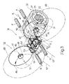
- Devices 32 are located on either side of and specular in relation to paths 6, and each comprise, as shown in Figure 2 (relative to device 32 to the right of paths 6 in Figure 1), a box body 33 projecting from body 24 in direction 5 and defined at the front, i.e. on the opposite side to that connected to body 24, by a flat wall 34, which is maintained crosswise to direction 5 at all times by disk 30, and is fitted through with a tubular bushing 35 integral with wall 34 and presenting outer teeth 36 and an axis 37 parallel to direction 5.
- Bushing 35 communicates with a chamber 38 defined by bodies 24 and 33, and which is fitted through with a portion of shaft 25 fitted with a helical gear 39 meshing with a helical gear 40 formed on the rear end of a shaft 41 coaxial with axis 37.
- Shaft 41 is supported in rotary manner by bushing 35, and presents a front end projecting frontwards of bushing 35 and connected integral with an intermediate portion of a cutting head 42 comprising an arm 43 extending crosswise to axis 37, and a counterweight 43a. Close to its free end, arm 43 presents a through hole engaged in rotary manner by a shaft 44, the axis 45 of which is parallel to axis 37.
- the rear end of shaft 44 is fitted with a gear 46 meshing with teeth 36; and the front end of shaft 44, to the front of arm 43, is fitted with a circular blade 47 presenting a circular outer cutting edge 48, which, as head 42 rotates about axis 37, travels along a circular trajectory 49 about axis 37.
- an appendix 50 projects frontwards from body 24, is located in an intermediate position between the two box bodies 33, is substantially parallel to direction 5, and is fitted integrally on its free end with two side by side counterblades 51, each of which is defined by a plate 52 substantially in the form of a rectangular prism and presenting a top groove 53 parallel to respective path 6, so that counterblade 51 is substantially U-shaped with its concavity facing upwards.
- Each counterblade 51 presents an intermediate transverse slit 54 extending the full width of groove 53 and which is engaged by respective blade 47, the trajectory 49 of edge 48 of which extends through slit 54.
- each cutting device 32 comprises a sharpening device 55 fitted to body 24 and in turn comprising a preferably powered grinding wheel 56 tangent to trajectory 49.
- shaft 9 rotates carrier 19 about axis 10 at substantially constant speed, and, by means of disk 30, the angular position of assemblies 31 (only one shown) is so controlled that they translate about axis 10 with axes 45 of blades 47 parallel at all times to paths 6 and direction 5.
- assemblies 31 translate about axis 10
- the point of intersection between the axis of each groove 53 and the plane of respective slit 54 travels along a circular trajectory 57, which is tangent to relative path 6 at station 7, and presents an axis 58 below and parallel to axis 10, so that, for each complete turn of shaft 9 about axis 10, each counterblade 51 is positioned tangent to relative cigarette rod 4 at station 7.
- each counterblade therefore travels through station 7 in direction 5 at the same speed as relative cigarette rod 4. That is, each counterblade 51 travels through station 7 at the same speed as and supporting cigarette rod 4.
- shaft 25 is rotated about axis 22 so that head 42 rotates about axis 37; and, at the same time, gear 46 meshes with teeth 36 to rotate blade 47 about respective axis 45.
- Connections 39-40 of each assembly 31 are such that the two heads 42 are rotated in opposite directions and in time with each other about respective axes 37. More specifically, heads 42 to the left and right of paths 6 in Figure 1 respectively rotate clockwise and anticlockwise about respective axes 37, so that respective blades 47 travel downwards through respective slits 54 and cut respective rods 4 by pressing them on to respective counterblades 51.
- each blade 47 may be fed through respective slit 54 to cut relative rod 4 as respective counterblade 51 travels through station 7.
- each counterblade 51 since each counterblade 51 travels with respective blade 47 along respective trajectory 57, the clearance between blade 47 and counterblade 51 may be very small, as may the width of respective slit 54, thus enabling a precise "clean" cut of relative rod 4 by blade 47. And this by means of a number of rotational movements at substantially constant speed, i.e. with substantially no vibration.
- FIG. 1 shows a cutting unit 8 comprising only one cutting assembly 31, in actual practice, unit 8 may of course comprise a number of assemblies 31 equally spaced about axis 10, the number of assemblies 31 depending on the ratio between the traveling speed of rods 4 and the linear speed of assemblies 31.
- each cutting assembly 31 will obviously comprise only one cutting device 32.
Landscapes
- Life Sciences & Earth Sciences (AREA)
- Forests & Forestry (AREA)
- Engineering & Computer Science (AREA)
- Mechanical Engineering (AREA)
- Manufacturing Of Cigar And Cigarette Tobacco (AREA)
- Wrapping Of Specific Fragile Articles (AREA)
Claims (11)
- Dispositif de coupe (32) pour couper des tiges de cigarettes continues (4), et comprenant un moyen de guidage (3) pour guider au moins une tige de cigarette continue (4) le long d'une trajectoire donnée (6) traversant une station de coupe (7) ; un corps de support (24) ; une contre-lame (51) pour supporter et guider ladite tige de cigarette (4), la contre-lame (51) étant parallèle à ladite trajectoire (6), étant d'un seul tenant avec le corps de support (24) et présentant une fente transversale intermédiaire (54) ; et une lame (47) montée sur le corps de support (24) et adaptée à se déplacer, relativement au corps de support (24), dans ladite fente (54) ; caractérisé en ce qu'il comprend des premiers moyens d'actionnement (9, 20, 30) pour faire tourner le corps de support (24) autour d'un premier axe (10) transversalement à ladite trajectoire (6) afin de déplacer ladite contre-lame (51) à la même vitesse que la tige de cigarette relative (4) le long d'une première trajectoire circulaire (57) tangente à ladite trajectoire (6) à ladite station de coupe (7) ; et des deuxièmes moyens d'actionnement (16, 18, 25, 41) pour déplacer la lame (47) dans ladite fente (54) lorsque la fente (54) est située à ladite station de coupe (7).
- Dispositif selon la revendication 1, caractérisé en ce que lesdits premiers moyens d'actionnement (9, 20, 30) comprennent un moyen de commande (30) coopérant avec ledit corps de support (24) afin de maintenir la contre-lame (51) parallèlement à elle-même et à ladite trajectoire (6) en permanence tandis que le corps de support (24) se déplace le long de ladite première trajectoire (57).
- Dispositif selon la revendication 1 ou 2, caractérisé en ce qu'il comprend une tête de coupe (42) montée en rotation sur ledit corps de support (24) de manière à tourner, grâce auxdits deuxièmes moyens d'actionnement (16, 18, 25, 41), autour d'un deuxième axe (37) sensiblement parallèle à ladite trajectoire (6) ; la tête de coupe (42) supportant ladite lame (47).
- Dispositif selon la revendication 3, caractérisé en ce que ladite lame (47) est une lame circulaire (47) montée sur ladite tête de coupe (42) excentriquement par rapport au deuxième axe (37), et présentant un bord de coupe périphérique (48) ; la lame (47) se déplaçant conjointement avec la tête de coupe (42) pour déplacer ledit bord de coupe (48) le long d'une deuxième trajectoire circulaire (49) traversant ladite fente (54).
- Dispositif selon la revendication 4, caractérisé en ce qu'il comprend des troisièmes moyens d'actionnement (36, 46) situés sur le corps de support (24) et pour entraíner la lame (47) en rotation autour d'un troisième axe (45) parallèle au deuxième axe (37).
- Dispositif selon la revendication 5, caractérisé en ce qu'il comprend un dispositif d'affûtage (55) monté sur le corps de support (24) et situé le long de ladite deuxième trajectoire (49), à une distance donnée de ladite contre-lame (51).
- Dispositif selon l'une quelconque des revendications précédentes 4 à 6, caractérisé en ce que ladite contre-lame (51) est une double contre-lame (51) présentant deux rainures côte à côte (53) pour supporter et guider deux dites tiges de cigarettes continues (4), chaque rainure (53) présentant une fente transversale respective (54) la traversant ; ledit corps de support (24) supportant deux dites têtes de coupe (42) situées sur chaque côté de ladite contre-lame (51) et chacune présentant une dite lame circulaire (47) respective.
- Dispositif selon la revendication 7, caractérisé en ce que lesdites deux têtes de coupe (42) sont montées sur ledit corps de support (24) afin de tourner dans des directions opposées autour desdits deuxièmes axes respectifs (37) .
- Unité de coupe pour couper des tiges de cigarettes continues (4), caractérisée en ce qu'elle comprend au moins deux dispositifs de coupe (32) selon l'une quelconque des revendications précédentes ; les dispositifs de coupe (32) étant agencés autour dudit premier axe (10), et ayant en commun lesdits premiers moyens d'actionnement (9, 20, 30) et ledit moyen de guidage (3).
- Dispositif selon l'une quelconque des revendications précédentes 1 à 8, caractérisé en ce que ladite contre-lame (51) a sensiblement la forme d'un U.
- Unité selon la revendication 9, caractérisée en ce que ladite contre-lame (51) a sensiblement la forme d'un U.
Applications Claiming Priority (2)
| Application Number | Priority Date | Filing Date | Title |
|---|---|---|---|
| IT95BO000597A IT1279717B1 (it) | 1995-12-21 | 1995-12-21 | Dispositivo di taglio per bachi continui di sigaretta |
| ITBO950597 | 1995-12-21 |
Publications (2)
| Publication Number | Publication Date |
|---|---|
| EP0780060A1 EP0780060A1 (fr) | 1997-06-25 |
| EP0780060B1 true EP0780060B1 (fr) | 2001-03-14 |
Family
ID=11340964
Family Applications (1)
| Application Number | Title | Priority Date | Filing Date |
|---|---|---|---|
| EP96120813A Expired - Lifetime EP0780060B1 (fr) | 1995-12-21 | 1996-12-23 | Dispositif pour couper des tiges de cigarette |
Country Status (5)
| Country | Link |
|---|---|
| US (1) | US5992282A (fr) |
| EP (1) | EP0780060B1 (fr) |
| CN (1) | CN1098050C (fr) |
| DE (1) | DE69612068T2 (fr) |
| IT (1) | IT1279717B1 (fr) |
Families Citing this family (16)
| Publication number | Priority date | Publication date | Assignee | Title |
|---|---|---|---|---|
| DE19961254A1 (de) * | 1999-12-18 | 2001-06-21 | Hauni Maschinenbau Ag | Verfahren und Vorrichtung zum Zertrennen mindestens eines endlosen bewegten Stranges der tabakverarbeitenden Industrie |
| DE102005024645A1 (de) * | 2005-05-25 | 2006-11-30 | Hauni Maschinenbau Ag | Vorrichtung zur Aufbereitung und/oder Herstellung von stabförmigen Gegenständen der tabakverarbeitenden Industrie |
| ITBO20060056A1 (it) * | 2006-02-02 | 2006-05-04 | Gd Spa | Dispositivo di taglio per articoli da fumo. |
| ITBO20060664A1 (it) | 2006-09-28 | 2006-12-28 | Gd Spa | Unita' di taglio per almeno un baco continuo |
| DE102009010090A1 (de) * | 2009-02-24 | 2010-09-09 | Hauni Maschinenbau Ag | Strangschneiden |
| DE102009022756A1 (de) * | 2009-05-26 | 2010-12-02 | Hauni Maschinenbau Ag | Schneidtube |
| DE102009024933A1 (de) * | 2009-06-06 | 2010-12-09 | Hauni Maschinenbau Ag | Schneidvorrichtung der Tabak verarbeitenden Industrie zum Schneiden wenigstens eines geförderten Strangs in eine Vielzahl stabförmiger Artikel sowie Verfahren zur Außerbetriebnahme der Schneidvorrichtung |
| DE102009041776A1 (de) * | 2009-09-15 | 2011-03-24 | Hauni Maschinenbau Ag | Messerträger für eine Schneidvorrichtung in Strangmaschinen der Tabak verarbeitenden Industrie |
| DE102010039480A1 (de) * | 2010-08-18 | 2012-02-23 | Hauni Maschinenbau Ag | Schneidvorrichtung einer Strangmaschine der Tabak verarbeitenden Industrie |
| DE102010056606A1 (de) * | 2010-12-28 | 2012-06-28 | Hauni Maschinenbau Ag | Schneideinrichtung für eine Strangmaschine der Tabak verarbeitenden Industrie und Verfahren zum Einstellen der Position eines Schleifscheibenhalters einer Vorrichtung zum Schleifen in einer Schneideinrichtung für eine Strangmaschine der Tabak verarbeitenden Industrie |
| DE102011102153A1 (de) * | 2011-05-20 | 2012-11-22 | Hauni Maschinenbau Ag | Schneideeinrichtung für eine Strangmaschine der Tabak verarbeitenden Industrie und Verfahren zum Einstellen der Position der oder jeder Schleifscheibe einer Schleifvorrichtung in einer Schneideinrichtung für eine Strangmaschine der Tabak verarbeitenden Industrie |
| ITBO20110469A1 (it) * | 2011-07-29 | 2013-01-30 | Gd Spa | Testa di taglio di almeno un baco continuo di una macchina per la produzione di articoli da fumo |
| PL230292B1 (pl) * | 2013-07-05 | 2018-10-31 | Int Tobacco Machinery Poland Spolka Z Ograniczona Odpowiedzialnoscia | Mechanizm prowadnicy cięcia maszyny wytwarzającej sztabki |
| CN105834754B (zh) * | 2016-03-30 | 2017-12-19 | 嵊州北航投星空众创科技有限公司 | 一种用于挂衣架转动式自动打磨机 |
| CN110076831A (zh) * | 2019-03-19 | 2019-08-02 | 东莞市香草生物工程有限公司 | 一种自动卷烟分切机 |
| CN113967943A (zh) * | 2020-07-09 | 2022-01-25 | 湖南中烟工业有限责任公司 | 烟支通用正轴打孔装置 |
Family Cites Families (10)
| Publication number | Priority date | Publication date | Assignee | Title |
|---|---|---|---|---|
| DE494488C (de) * | 1930-03-24 | Eduard Quester | Zigarettenstrangschneidvorrichtung | |
| DE1191275B (de) * | 1962-07-14 | 1965-04-15 | Hauni Werke Koerber & Co Kg | Vorrichtung zum Durchschneiden eines fortlaufenden Tabak- oder aehnlichen Stranges |
| GB1170305A (en) * | 1966-12-15 | 1969-11-12 | Hauni Werke Koerber & Co Kg | Cutting Device for a Continuous Rod Machine for Producing Cigarettes or the like |
| GB1315935A (en) * | 1969-06-13 | 1973-05-09 | Molins Machine Co Ltd | Cut-off devices for continuous rod cigarette-making machines and other similar machines |
| FR2023054A1 (fr) * | 1969-11-07 | 1970-08-07 | American Mach & Foundry | |
| GB1351130A (en) * | 1970-05-26 | 1974-04-24 | Molins Ltd | Cut-off devices for continuous-rod making machines |
| US3850065A (en) * | 1970-10-20 | 1974-11-26 | Molins Ltd | Rod making machines |
| US3760672A (en) * | 1971-10-19 | 1973-09-25 | Molins Ltd | Rod-making machines |
| DE2746915A1 (de) * | 1977-10-19 | 1979-04-26 | Hauni Werke Koerber & Co Kg | Vorrichtung zum fuehren von werkzeugen an tabakverarbeitenden maschinen |
| IT1148241B (it) * | 1980-12-12 | 1986-11-26 | Gd Spa | Dispositivo per il taglio contemporaneo di due bachi continui di sigaretta |
-
1995
- 1995-12-21 IT IT95BO000597A patent/IT1279717B1/it active IP Right Grant
-
1996
- 1996-12-20 CN CN96121587A patent/CN1098050C/zh not_active Expired - Fee Related
- 1996-12-23 US US08/771,956 patent/US5992282A/en not_active Expired - Fee Related
- 1996-12-23 DE DE69612068T patent/DE69612068T2/de not_active Expired - Fee Related
- 1996-12-23 EP EP96120813A patent/EP0780060B1/fr not_active Expired - Lifetime
Also Published As
| Publication number | Publication date |
|---|---|
| IT1279717B1 (it) | 1997-12-16 |
| ITBO950597A0 (it) | 1995-12-21 |
| DE69612068D1 (de) | 2001-04-19 |
| ITBO950597A1 (it) | 1997-06-21 |
| US5992282A (en) | 1999-11-30 |
| DE69612068T2 (de) | 2001-08-16 |
| CN1098050C (zh) | 2003-01-08 |
| CN1155403A (zh) | 1997-07-30 |
| EP0780060A1 (fr) | 1997-06-25 |
Similar Documents
| Publication | Publication Date | Title |
|---|---|---|
| EP0780060B1 (fr) | Dispositif pour couper des tiges de cigarette | |
| EP0507750B1 (fr) | Machine pour le découpage de rouleaux de matériau en bande | |
| EP1905316B1 (fr) | Unité de découpage pour couper au moins une tige continue | |
| US4922775A (en) | Device for cutting contoured labels | |
| US5452598A (en) | Automatic spring formation apparatus | |
| US1802554A (en) | Rotary flying shears | |
| US20060162522A1 (en) | Cutting machine for cutting elongated products | |
| US5311802A (en) | Tube cut off machine | |
| CN1933742B (zh) | 制造香烟的装置 | |
| JPH0321304B2 (fr) | ||
| US4919025A (en) | Method and apparatus for processing continuously manufactured tubing | |
| JPH04275820A (ja) | チューブの切断機と切断方法 | |
| JPH07285024A (ja) | 歯車の製造方法および装置 | |
| US4939967A (en) | Cut-off machine | |
| US4163345A (en) | Arrangement for the grinding of rotary profile cutters | |
| US3670458A (en) | Programmed contouring machine for machining, by tool heads, irregularly shaped workpieces | |
| SU730288A3 (ru) | Способ обработки зубчатых изделий и станок дл его осуществлени | |
| US1242478A (en) | Cutter-head for cigarette-machines. | |
| US3380331A (en) | Apparatus for sectioning moving articles | |
| US3440912A (en) | Cutting guide notably for cigarette machines | |
| US2824556A (en) | Method and means for shaping and trimming helically formed grinding wheels | |
| US2145000A (en) | Machine for generating gears | |
| US5344262A (en) | Slotting apparatus for producing a slot in inner circumferential surface of tubular workpiece | |
| US3687006A (en) | Attachment for cutting rack gear teeth of variable pitch | |
| GB2139135A (en) | A slitting and cutting machine |
Legal Events
| Date | Code | Title | Description |
|---|---|---|---|
| PUAI | Public reference made under article 153(3) epc to a published international application that has entered the european phase |
Free format text: ORIGINAL CODE: 0009012 |
|
| AK | Designated contracting states |
Kind code of ref document: A1 Designated state(s): DE FR GB IT |
|
| 17P | Request for examination filed |
Effective date: 19971126 |
|
| GRAG | Despatch of communication of intention to grant |
Free format text: ORIGINAL CODE: EPIDOS AGRA |
|
| 17Q | First examination report despatched |
Effective date: 20000518 |
|
| GRAG | Despatch of communication of intention to grant |
Free format text: ORIGINAL CODE: EPIDOS AGRA |
|
| GRAH | Despatch of communication of intention to grant a patent |
Free format text: ORIGINAL CODE: EPIDOS IGRA |
|
| GRAH | Despatch of communication of intention to grant a patent |
Free format text: ORIGINAL CODE: EPIDOS IGRA |
|
| GRAA | (expected) grant |
Free format text: ORIGINAL CODE: 0009210 |
|
| AK | Designated contracting states |
Kind code of ref document: B1 Designated state(s): DE FR GB IT |
|
| ITF | It: translation for a ep patent filed | ||
| REF | Corresponds to: |
Ref document number: 69612068 Country of ref document: DE Date of ref document: 20010419 |
|
| ET | Fr: translation filed | ||
| REG | Reference to a national code |
Ref country code: GB Ref legal event code: IF02 |
|
| PLBE | No opposition filed within time limit |
Free format text: ORIGINAL CODE: 0009261 |
|
| STAA | Information on the status of an ep patent application or granted ep patent |
Free format text: STATUS: NO OPPOSITION FILED WITHIN TIME LIMIT |
|
| 26N | No opposition filed | ||
| PGFP | Annual fee paid to national office [announced via postgrant information from national office to epo] |
Ref country code: GB Payment date: 20031217 Year of fee payment: 8 |
|
| PGFP | Annual fee paid to national office [announced via postgrant information from national office to epo] |
Ref country code: FR Payment date: 20031218 Year of fee payment: 8 |
|
| PGFP | Annual fee paid to national office [announced via postgrant information from national office to epo] |
Ref country code: DE Payment date: 20040202 Year of fee payment: 8 |
|
| PG25 | Lapsed in a contracting state [announced via postgrant information from national office to epo] |
Ref country code: GB Free format text: LAPSE BECAUSE OF NON-PAYMENT OF DUE FEES Effective date: 20041223 |
|
| PG25 | Lapsed in a contracting state [announced via postgrant information from national office to epo] |
Ref country code: DE Free format text: LAPSE BECAUSE OF NON-PAYMENT OF DUE FEES Effective date: 20050701 |
|
| GBPC | Gb: european patent ceased through non-payment of renewal fee |
Effective date: 20041223 |
|
| PG25 | Lapsed in a contracting state [announced via postgrant information from national office to epo] |
Ref country code: FR Free format text: LAPSE BECAUSE OF NON-PAYMENT OF DUE FEES Effective date: 20050831 |
|
| REG | Reference to a national code |
Ref country code: FR Ref legal event code: ST |
|
| PG25 | Lapsed in a contracting state [announced via postgrant information from national office to epo] |
Ref country code: IT Free format text: LAPSE BECAUSE OF NON-PAYMENT OF DUE FEES Effective date: 20051223 |