EP0780181B1 - Chariot pour scie pivotante - Google Patents
Chariot pour scie pivotante Download PDFInfo
- Publication number
- EP0780181B1 EP0780181B1 EP96309219A EP96309219A EP0780181B1 EP 0780181 B1 EP0780181 B1 EP 0780181B1 EP 96309219 A EP96309219 A EP 96309219A EP 96309219 A EP96309219 A EP 96309219A EP 0780181 B1 EP0780181 B1 EP 0780181B1
- Authority
- EP
- European Patent Office
- Prior art keywords
- saw
- blade
- assembly
- support
- slot
- Prior art date
- Legal status (The legal status is an assumption and is not a legal conclusion. Google has not performed a legal analysis and makes no representation as to the accuracy of the status listed.)
- Expired - Lifetime
Links
Images




Classifications
-
- B—PERFORMING OPERATIONS; TRANSPORTING
- B23—MACHINE TOOLS; METAL-WORKING NOT OTHERWISE PROVIDED FOR
- B23D—PLANING; SLOTTING; SHEARING; BROACHING; SAWING; FILING; SCRAPING; LIKE OPERATIONS FOR WORKING METAL BY REMOVING MATERIAL, NOT OTHERWISE PROVIDED FOR
- B23D45/00—Sawing machines or sawing devices with circular saw blades or with friction saw discs
- B23D45/04—Sawing machines or sawing devices with circular saw blades or with friction saw discs with a circular saw blade or the stock carried by a pivoted lever
- B23D45/042—Sawing machines or sawing devices with circular saw blades or with friction saw discs with a circular saw blade or the stock carried by a pivoted lever with the saw blade carried by a pivoted lever
- B23D45/046—Sawing machines or sawing devices with circular saw blades or with friction saw discs with a circular saw blade or the stock carried by a pivoted lever with the saw blade carried by a pivoted lever the pivoted lever being mounted on a carriage
- B23D45/048—Sawing machines or sawing devices with circular saw blades or with friction saw discs with a circular saw blade or the stock carried by a pivoted lever with the saw blade carried by a pivoted lever the pivoted lever being mounted on a carriage the saw blade being adjustable according to angle of cut
-
- Y—GENERAL TAGGING OF NEW TECHNOLOGICAL DEVELOPMENTS; GENERAL TAGGING OF CROSS-SECTIONAL TECHNOLOGIES SPANNING OVER SEVERAL SECTIONS OF THE IPC; TECHNICAL SUBJECTS COVERED BY FORMER USPC CROSS-REFERENCE ART COLLECTIONS [XRACs] AND DIGESTS
- Y10—TECHNICAL SUBJECTS COVERED BY FORMER USPC
- Y10T—TECHNICAL SUBJECTS COVERED BY FORMER US CLASSIFICATION
- Y10T83/00—Cutting
- Y10T83/768—Rotatable disc tool pair or tool and carrier
- Y10T83/7684—With means to support work relative to tool[s]
- Y10T83/7722—Support and tool relatively adjustable
- Y10T83/7726—By movement of the tool
-
- Y—GENERAL TAGGING OF NEW TECHNOLOGICAL DEVELOPMENTS; GENERAL TAGGING OF CROSS-SECTIONAL TECHNOLOGIES SPANNING OVER SEVERAL SECTIONS OF THE IPC; TECHNICAL SUBJECTS COVERED BY FORMER USPC CROSS-REFERENCE ART COLLECTIONS [XRACs] AND DIGESTS
- Y10—TECHNICAL SUBJECTS COVERED BY FORMER USPC
- Y10T—TECHNICAL SUBJECTS COVERED BY FORMER US CLASSIFICATION
- Y10T83/00—Cutting
- Y10T83/768—Rotatable disc tool pair or tool and carrier
- Y10T83/7684—With means to support work relative to tool[s]
- Y10T83/773—Work-support includes passageway for tool [e.g., slotted table]
-
- Y—GENERAL TAGGING OF NEW TECHNOLOGICAL DEVELOPMENTS; GENERAL TAGGING OF CROSS-SECTIONAL TECHNOLOGIES SPANNING OVER SEVERAL SECTIONS OF THE IPC; TECHNICAL SUBJECTS COVERED BY FORMER USPC CROSS-REFERENCE ART COLLECTIONS [XRACs] AND DIGESTS
- Y10—TECHNICAL SUBJECTS COVERED BY FORMER USPC
- Y10T—TECHNICAL SUBJECTS COVERED BY FORMER US CLASSIFICATION
- Y10T83/00—Cutting
- Y10T83/768—Rotatable disc tool pair or tool and carrier
- Y10T83/7755—Carrier for rotatable tool movable during cutting
-
- Y—GENERAL TAGGING OF NEW TECHNOLOGICAL DEVELOPMENTS; GENERAL TAGGING OF CROSS-SECTIONAL TECHNOLOGIES SPANNING OVER SEVERAL SECTIONS OF THE IPC; TECHNICAL SUBJECTS COVERED BY FORMER USPC CROSS-REFERENCE ART COLLECTIONS [XRACs] AND DIGESTS
- Y10—TECHNICAL SUBJECTS COVERED BY FORMER USPC
- Y10T—TECHNICAL SUBJECTS COVERED BY FORMER US CLASSIFICATION
- Y10T83/00—Cutting
- Y10T83/768—Rotatable disc tool pair or tool and carrier
- Y10T83/7755—Carrier for rotatable tool movable during cutting
- Y10T83/7763—Tool carrier reciprocable rectilinearly
-
- Y—GENERAL TAGGING OF NEW TECHNOLOGICAL DEVELOPMENTS; GENERAL TAGGING OF CROSS-SECTIONAL TECHNOLOGIES SPANNING OVER SEVERAL SECTIONS OF THE IPC; TECHNICAL SUBJECTS COVERED BY FORMER USPC CROSS-REFERENCE ART COLLECTIONS [XRACs] AND DIGESTS
- Y10—TECHNICAL SUBJECTS COVERED BY FORMER USPC
- Y10T—TECHNICAL SUBJECTS COVERED BY FORMER US CLASSIFICATION
- Y10T83/00—Cutting
- Y10T83/869—Means to drive or to guide tool
- Y10T83/8773—Bevel or miter cut
Definitions
- the invention relates to a saws according to the preamble of claim 1.
- Such saws are known and described in published patent documents such as EP-0133666 and EP-0450400. These saws are useful and have numerous possibilities for enhancement to improve the capacity, capability and efficiency not to mention cleanliness and safety of their arrangements. On the other hand, all these features add complexity and cost, and may render the saw user unfriendly.
- the present invention particularly, although not exclusively, relates to saws of the type described above but which in addition have the table mounted in a frame such that the table may be inverted, as by pivoting about an axis, so that the saw assembly is then beneath the table.
- the table is in addition provided with a slot so that the blade can protrude through the slot to render the saw a bench or table saw.
- Such saws are known and described in DE-1628992, EP-0502350 and EP-0586172.
- both EP-0133666 and EP-0450400 mentioned above describe saws in which the saw assembly comprises an upper guard and a lower guard for the blade.
- the upper guard is formed from the housing of the assembly and permanently covers a top part of the blade. A bottom part of the blade is covered by the lower guard but this must be withdrawn in use so that the blade is exposed when required to perform cutting operations.
- a handle is disposed on the upper guard by means of which a user can pivot the saw assembly up and down to perform cutting operations on a workpiece supported on the table. Further, if the table has a rotational portion carrying the saw assembly, mitre cuts can also be made in a workpiece on the table.
- the lower guard may be opened entirely by an actuating lever disposed on the handle.
- the guard may be opened automatically by pivoting of the saw assembly, there being provided a connection between the guard and the pivot member for this purpose.
- the guard may be opened partly by either of these arrangements and only further opened by direct contact with a workpiece.
- Means must be provided to bias the saw assembly to a raised upright position when it is at rest so that the user is not required to lift the not-insignificant weight of the saw assembly after completing a plunge cut.
- Such means is normally in the form of a powerful spring.
- EP-0133666 discloses a saw in which the motor assembly is supported by a pair of shafts which are received within a pair of channels formed in a support.
- the saw assembly is mounted on the shafts such that the saw assembly can slide relative to the support to extend the reach of the saw.
- the saw assembly is located forwardly of and at the same height as the support in a cantilevered manner, so that a torsional force is created at the channel/shaft interface.
- the weight of the saw assembly is located forwardly of the support in this cantilevered fashion which means that a strong shaft/channel interface is necessary in order to support the weight of the saw assembly and guide the saw assembly in such a way that the saw assembly can be moved reliably along its path of travel in order to make accurate cuts.
- Such an interface will require bulky and/or expensive components to provide the necessary support and guidance to the saw assembly.
- a saw comprising a table, a support mounted on the table, a saw assembly, the saw assembly including a blade journalled in the assembly and a motor to drive the blade, and a slot in the table through which the blade can be plunged, wherein the support defines a channel which receives a shaft carried by the saw assembly such that the saw assembly can slide relative to the support to extend the reach of the saw blade along the slot, characterised in that the saw assembly slides over and above the support such that the weight of the saw assembly is transferred to the table substantially vertically through the support. In this way twisting forces on the support are reduced. Further, the space taken up by the saw assembly and support is reduced.
- the support defines two parallel channels and two corresponding shafts are carried below the saw assembly for sliding along the channels. Improved support for the saw assembly is thereby provided.
- the or each channel is preferably C-shaped in cross-section.
- the shafts are preferably shaped to conform to the cross-section of the channels. It will, of course, be appreciated that the shafts (or rods) need only to be shaped to be retained within the channels and do not have to be shaped to conform to the cross-sections of the channels.
- the or each channel preferably includes a bearing between the support and the shaft.
- a low friction material such as PTFE, may be used to reduce the friction between the shafts and the channels.
- the saw assembly includes a detent for holding the assembly in a retracted position on the support until the saw blade is plunged towards the slot.
- This detent preferably automatically re-engages when the saw assembly returns to its start position.
- the support includes a pivot block fixed to the table and a pivot member which defines the or each channel, the pivot member being pivotable relative to the pivot block to adjust the angle of cut of the saw blade so that bevel cuts can be made.
- a retraction mechanism may act between the pivot block and the pivot member to urge the saw blade into a preferred position, which may be substantially perpendicular to the slot.
- the saw assembly may include a quadrilateral linkage which, as the saw blade is plunged towards the slot, opens a blade guard to expose the saw blade.
- the saw assembly preferably further comprises a motor plate which carries the or each shaft and spring means between the motor plate and the motor which act to raise the blade away from the slot.
- spring means By including such spring means, a user of the saw does not have to raise the not-insignificant weight of the saw assembly at the end of a cut.
- the spring means preferably comprise a spring and a lever which, when rotated, releases the tension in the spring to lower the saw blade. This is important if the saw is to be used as a table saw rather than as a plunge (or chop) saw.
- the motor plate carries a locking device for locking the lever to prevent movement of the saw blade.
- the spring means may further comprise a worm drive which, when the lever is rotated, is brought into engagement with a rack mounted on the motor, such that the worm drive can be used to control the position of the saw blade relative to the slot.
- the rack is preferably formed on an extension of the linkage.
- a toggle lever carried by the saw assembly may be used to lock the saw assembly position.
- the present invention is particularly applicable to chop saws, it may also be applied to saws which can act as both a chop saw and a table saw.
- the table is preferably mounted in a frame and adapted to adopt two positions, in a first of said two positions of the table the saw assembly is above the table, the saw thereby forming a chop saw for performing plunge cuts on workpieces supported on a first side of the table, and, in a second of said two positions of the table, the saw assembly is below the table and the saw thereby forms a bench saw for performing cuts on workpieces passing through the blade on a second opposite side of the table.
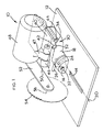
- a saw 10 comprises a table 12 having a slot 14 and a pivot block 16 rigidly fixed to the table.
- a pivot member 18 is pivoted to the pivot block about an axis 20 lying in the plane of the table 12 and passing along the slot 14.
- a bolt 22 received in the pivot block 16 passes through an arcuate slot 24 in the pivot member and is terminated with a lever 26 by means of which the bolt may be tightened to secure the pivot member in any angular position between two limits.
- the pivot member 18 also comprises a bearing cage 30 having two parallel C-shaped bearing channels 32, 34 including C-shaped bearings (not visible in Figure 1).
- a motor plate 40 has two bars 42, 44 rigidly fixed to it, and the bars are received in the channels 32, 34 respectively. The plate can therefore slide back and forth relative to the pivot member and the bars and channels are so arranged that the direction of slide is always parallel the axis 20 (and slot 14).
- the channels are open in section and the connection to the shafts 32,34 is through the open channel, the length of the shafts can be minimised for the given travel of the saw assembly and the mechanical support requirements of the saw assembly through the bearings. This is further enhanced by the weight distribution of the saw assembly and motor plate through the bearings, which, despite not having a full circumference, can be small because there are less torsional stresses on them about an axis parallel axis 50. This is important given the desire to minimise the bulk of the final saw and the working room required for its satisfactory operation. This is particularly the case where the saw is a pivoting saw where the table 12 is arranged to pivot in a frame. The frame should be kept to a minimum in size for easier transportation, and reduced working room requirements, and the present arrangement facilitates that end by minimising the intrusion of the slide system within the overall volume envelope of the saw.
- a motor 48 has another hinge part 47 which is joined to hinge parts 46 through an axle which enables pivoting of the motor relative to the plate 40 about an axis 50.
- the motor 48 is fixed to a blade assembly 52 which includes a saw blade 54 driven by the motor 48.
- the axis 56 of the blade is parallel the axis of the motor and axis 50.
- the blade is arranged above the slot 14 so that pivoting of the motor about axis 50 plunges the blade into the slot 14, at whatever angle the pivot member 18 is with respect to the pivot block 16.
- the slot 14 is long enough to accommodate full movement of the plate 40 back and forth with respect to the pivot member 18, even with the blade plunged fully downwards.
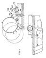
- the plate 40 is carried by the bearing cage 30.
- the bearings 32, 34 are retained by set screws 33.
- the bars 42, 44 are secured to the plate 40 by screws 43, staggered with respect to one another along the length of the bars 42, 44.
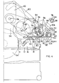
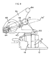
- Figure 3 shows the extent of the plate 40 and the cage 30. Also, at the back of plate 40 is mounted spring release lever 60, which is mounted for rotation about axis 62 in the plate 40. An eccentric catch element 64 retains one end of a tension spring 66. The lever 60 is received firstly in a large aperture 68 in an arm 70 upstanding from the plate 40, and secondly in a bracket 72 fixed to the plate 40 by screws 73.
- the spring 66 acts between the element 64 on the lever 60 and a catch 74 on the side of the motor 48 at its front end (see also Figure 7).
- pivoting of the motor 48 about axis 50 to plunge the blade 54 into slot 14
- tensions the spring 66 which is of course arranged strong enough to lift the motor and saw assembly when released by the user from a plunged position.
- Blade assembly 52 includes a parallelogram lever 80 which at the top end is pivoted to an upper blade guard 82 which is also pivoted about the blade axis 56. At its lower end, the lever 80 is pivoted to the upstanding arm 70 about axis 84. An extension 200 at the top end of the lever 80 prevents the blade assembly 52 from being plunged down unless switch lever 202 is pulled. Switch 202 is mounted on handle 204 fixed to the upper blade guard 82. Lever 202 when first pulled rotates lower blade guard 206 a small amount so that a cam 208 on the lower blade guard is released from blocking engagement with extension 200. Thereafter, further opening of the lower blade guard is accomplished by action of the extension 200 on the front face of cam 208. A spring (not shown) biasses the lower blade guard to its covering position with respect to the blade 54. When the assembly is permitted to pivot down, however, the parallelogram lever 80 maintains the disposition of the upper guard with respect to the table 12.
- Pivoting down of the motor 48 and blade assembly 52 releases a detent 86 connected to the back of the motor 48 and which otherwise catches, at its lower end 88, against the back of the bearing cage 30 and prevents the plate 40 sliding along the cage 30.
- the lower end 88 is pivoted to the detent 86 at 90 so that, when the blade assembly 52, motor 48 and plate 40 are slid forwardly to a front position (not shown) and the blade assembly 52 is permitted to rise under the action of the spring 66, the detent does not prevent such raising.
- catch 88 On such raising of the blade assembly 52, the catch 88 is merely deflected by contact with the top of the cage 30 about axis 90 until the plate 40 is slid back to the position shown in Figure 4,: whereupon catch 88 snaps off the cage 30 under the action of a spring 92.
- An extension 94 at the lower end of the lever 80 has a rack 96 formed thereon.
- a worm assembly 98 is pivoted about axis 100 to the upstanding arm 70 (see also inset to Figure 2).
- a flat surface 102 between its ends faces the back of worm assembly 98 so that the worm assembly lies with its back at the position shown at 98'.
- the worm assembly is not contacted by the rack 96 when the assembly is pivoted down, and the rack and worm assembly have no function.
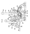
- a key 61 on the end of the spring release lever 60 limits the rotation of the lever between two positions, and, at least in the position shown in Figure 4, locks lever in that position, in the sense that the spring 66 pressure presses the key 61 against its stop.
- a lock 108 which can be employed to lock the plate 40 in position at one end of the cage 30.
- the lock has a toggle lever 110 by means of which the lock may be permanently disengaged (see also Figure 8).
- Figure 6 shows a retraction mechanism 112 fixed to the plate 40 which has a spring loaded cable 114, one end 116 of which is connected to the cage 30. This serves to bias the blade assembly 52 and plate 40 back to the position shown in Figure 4.
Landscapes
- Engineering & Computer Science (AREA)
- Mechanical Engineering (AREA)
- Sawing (AREA)
Claims (16)
- Scie (10) comprenant une table (12), un support (30) monté sur la table, un ensemble de scie (40, 48, 52, 54), l'ensemble de scie comprenant une lame (54) montée dans l'ensemble et un moteur (48) pour entraíner la lame, et une fente (14) dans la table à travers laquelle la lame peut plonger, dans laquelle le support (30) définit un canal (32, 34) qui reçoit un arbre (42, 44) supporté par l'ensemble de scie de telle sorte que l'ensemble de scie puisse coulisser par rapport au support afin d'étendre la portée de la lame de scie le long de la fente, caractérisée en ce que l'ensemble de. scie (40, 48, 52, 54) coulisse sur et au-dessus du support (30) de telle sorte que le poids de l'ensemble de scie soit transféré à la table (12) sensiblement verticalement à travers le support.
- Scie selon la revendication 1, caractérisée en ce que le support (40, 48, 52, 54) définit deux canaux parallèles (32, 34) et deux arbres correspondants (42, 44) sont supportés au-dessous de l'ensemble de scie pour coulisser le long des canaux.
- Scie selon la revendication 1 ou la revendication 2, caractérisée en ce que le ou chaque canal (32, 34) a une section transversale en C.
- Scie selon l'une quelconque des revendications précédentes, caractérisée en ce que le ou chaque canal comprend un palier (32, 34) entre le support et l'arbre (42, 44).
- Scie selon l'une quelconque des revendications précédentes, caractérisée en ce que l'ensemble de scie (40, 48, 52, 54) comprend un verrou (86) pour maintenir l'ensemble dans une position rétractée sur le support (30) jusqu'à ce que la lame de scie (54) ait plongé vers la fente (14).
- Scie selon l'une quelconque des revendications précédentes, caractérisée en ce que le support (30) comprend un bloc de pivotement (16) fixé à la table (12) et un élément de pivotement (18) qui définit le ou chaque canal (32, 34), l'élément de pivotement étant capable de pivoter par rapport au bloc de pivotement afin d'ajuster l'angle de coupe de la lame de scie (54).
- Scie selon la revendication 6, caractérisée en ce qu'un mécanisme de rétraction (112) agit entre le bloc de pivotement (16) et l'élément de pivotement (18) afin de pousser la lame de scie (54) dans une position sensiblement perpendiculaire à la fente (14).
- Scie selon l'une quelconque des revendications précédentes, caractérisée en ce que l'ensemble de scie (40, 48, 52, 54) comprend une tringlerie quadrilatérale (80) qui, alors que la lame de scie (54) plonge vers la fente (14), ouvre un protège-lame (206) afin de mettre à découvert la lame de scie.
- Scie selon l'une quelconque des revendications précédentes, caractérisée en ce que l'ensemble de scie (40, 48, 52, 54) comprend en outre une plaque de moteur (40) qui supporte le ou chaque arbre (42, 44) et des moyens formant ressort (66) entre la plaque de moteur et le moteur (48) qui servent à lever la lame (54) hors de la fente (14).
- Scie selon la revendication 9, caractérisée en ce que les moyens formant ressort comprennent un ressort (66) et un levier (60) qui, lorsqu'il cst tourné, relâche la tension du ressort afin d'abaisser la lame de scie (54).
- Scie selon la revendication 10, caractérisée en ce que la plaque de moteur (40) supporte un dispositif de verrouillage pour verrouiller le levier (60).
- Scie selon la revendication 9, la revendication 10 ou la revendication 11, caractérisée en ce que les moyens formant ressort comprennent, en outre, un entraínement à vis sans fin (98) qui, lorsque le levier (60) est tourné, est mis en prise avec une crémaillère (96) montée sur le moteur (48), de telle sorte que l'entraínement à vis sans fin puisse être utilisé pour commander la position de la lame de scie (54) par rapport à la fente (14).
- Scie selon la revendication 12 lorsqu'elle dépend de la revendication 8, caractérisée en ce que la crémaillère (96) est formée sur une extension de la tringlerie quadrilatérale (80).
- Scie selon l'une quelconque des revendications précédentes, caractérisée en ce que des moyens sont prévus pour verrouiller l'ensemble de scie (40, 48, 52, 54) à n'importe quelle position par rapport au support (30).
- Scie selon la revendication 14, caractérisée en ce que les moyens pour verrouiller comprennent un levier articulé (110) supporté par l'ensemble de scie (40, 48, 52, 54).
- Scie selon l'une quelconque des revendications précédentes, caractérisée en ce que la table (12) est montée dans un bâti et adaptée pour adopter deux positions, dans la première desdites deux positions de la table, l'ensemble de scie (40, 48, 52, 54) étant au-dessus de la table, la scie formant de ce fait une scie de tranchage pour effectuer des coupes en plongée sur des pièces à usiner supportées d'un premier côté de la table, et, dans une deuxième desdites deux positions de la table, l'ensemble de scie étant au-dessous de la table et la scie formant, de ce fait, une scie d'établi pour effectuer des coupes sur des pièces à usiner passées sur la lame d'un deuxième côte opposé de la table.
Applications Claiming Priority (2)
| Application Number | Priority Date | Filing Date | Title |
|---|---|---|---|
| GBGB9526374.5A GB9526374D0 (en) | 1995-12-22 | 1995-12-22 | A chop/slide saw |
| GB9526374 | 1995-12-22 |
Publications (2)
| Publication Number | Publication Date |
|---|---|
| EP0780181A1 EP0780181A1 (fr) | 1997-06-25 |
| EP0780181B1 true EP0780181B1 (fr) | 2002-09-11 |
Family
ID=10785968
Family Applications (1)
| Application Number | Title | Priority Date | Filing Date |
|---|---|---|---|
| EP96309219A Expired - Lifetime EP0780181B1 (fr) | 1995-12-22 | 1996-12-16 | Chariot pour scie pivotante |
Country Status (4)
| Country | Link |
|---|---|
| US (1) | US5896798A (fr) |
| EP (1) | EP0780181B1 (fr) |
| DE (1) | DE69623578T2 (fr) |
| GB (1) | GB9526374D0 (fr) |
Families Citing this family (12)
| Publication number | Priority date | Publication date | Assignee | Title |
|---|---|---|---|---|
| US6052785A (en) * | 1997-11-21 | 2000-04-18 | International Business Machines Corporation | Multiple remote data access security mechanism for multitiered internet computer networks |
| JP4034873B2 (ja) | 1998-04-16 | 2008-01-16 | 大見工業株式会社 | ワーク切断機 |
| ES2209096T5 (es) | 1998-11-20 | 2007-11-01 | Mikron Sa Agno | Dispositivo para la generacion de un movimiento relativo. |
| US6173635B1 (en) * | 1999-04-23 | 2001-01-16 | Kevin C. Y. Chang | Base structure of a circular saw |
| US6530303B1 (en) * | 1999-06-10 | 2003-03-11 | Black & Decker Inc. | Table saw |
| US6918330B2 (en) | 2000-10-24 | 2005-07-19 | Thomson Industries, Inc. | Adjustable tool station |
| DE10302066A1 (de) * | 2003-01-21 | 2004-07-29 | Kolbus Gmbh & Co. Kg | Vorrichtung zum Trennsägen von Doppelnutzen |
| US20050247178A1 (en) * | 2004-04-15 | 2005-11-10 | Hetcher Jason D | Power tool having an elastomeric material |
| TWI341781B (en) * | 2004-09-03 | 2011-05-11 | Black & Decker Inc | Trunnion assembly for saws |
| US20060243113A1 (en) * | 2005-04-29 | 2006-11-02 | Kaye Thomas R Jr | Bevel lock assembly for miter saws |
| US7793568B2 (en) * | 2008-07-16 | 2010-09-14 | Nmtc, Inc. | Ratchet mechanism |
| US10875109B1 (en) | 2018-04-30 | 2020-12-29 | Kreg Enterprises, Inc. | Adaptive cutting system |
Family Cites Families (20)
| Publication number | Priority date | Publication date | Assignee | Title |
|---|---|---|---|---|
| US3296914A (en) * | 1965-01-29 | 1967-01-10 | Line Corp K | High speed cut off saw |
| DE2856038C2 (de) * | 1978-12-23 | 1982-09-30 | Chr. Eisele Maschinenfabrik GmbH & Co KG, 7316 Köngen | Schutzvorrichtung für das Kreissägeblatt von Kippkreissägemaschinen |
| US4318324A (en) * | 1980-09-22 | 1982-03-09 | Rock Mill, Inc. | Cutting machine with guard for cutting blade |
| US4581966A (en) * | 1983-06-11 | 1986-04-15 | Black & Decker, Inc. | Chop saw linkage system for moving saw guard |
| DE3329496C2 (de) | 1983-08-16 | 1986-02-06 | Eugen Lutz GmbH u. Co Maschinenfabrik, 7130 Mühlacker | Sägeeinrichtung |
| EP0133166A1 (fr) * | 1984-03-12 | 1985-02-13 | Centro Autoradio Hi-Fi | Dispositif de fixation de récepteur-radio dans un tableau de bord ou analogue afin d'en empêcher le vol |
| US4614140A (en) * | 1984-05-31 | 1986-09-30 | Macksoud Albert A | Safety device for rocking arm saw |
| JPH0634897Y2 (ja) * | 1987-01-12 | 1994-09-14 | リョービ株式会社 | テーブルソーのロアーガード装置 |
| JPH0518082Y2 (fr) | 1987-02-20 | 1993-05-14 | ||
| JPS63251117A (ja) * | 1987-04-03 | 1988-10-18 | Hitachi Koki Co Ltd | 切断機の移動ガ−ド回動装置 |
| US4875398A (en) * | 1988-01-15 | 1989-10-24 | Atlantic Richfield Company | Retractable dust control hood and guard for rotary table saw |
| JP2573057B2 (ja) * | 1989-07-07 | 1997-01-16 | 株式会社マキタ | 卓上丸鋸盤 |
| US5054352A (en) * | 1989-01-17 | 1991-10-08 | Makita Electric Wroks, Ltd. | Miter saw |
| DE3923470A1 (de) * | 1989-07-15 | 1991-01-24 | Metabowerke Kg | Kombinierte kapp- und tischkreissaege |
| DE4010455A1 (de) | 1990-03-31 | 1991-10-02 | Elektra Beckum Lubitz & Co | Saegeeinrichtung mit pendelschutzhaube am saegeaggregat |
| JPH0624161Y2 (ja) * | 1990-06-29 | 1994-06-29 | リョービ株式会社 | 卓上スライド丸鋸盤 |
| DE4106635C1 (fr) | 1991-02-28 | 1992-07-23 | Black & Decker Inc., Newark, Del., Us | |
| GB9218363D0 (en) | 1992-08-28 | 1992-10-14 | Black & Decker Inc | Pivoting power tool with table |
| GB9314164D0 (en) * | 1993-07-08 | 1993-08-18 | Black & Decker Inc | Chop saw arrangement |
| GB9314165D0 (en) * | 1993-07-08 | 1993-08-18 | Black & Decker Inc | Chop/table saw with parallelogram arrangement |
-
1995
- 1995-12-22 GB GBGB9526374.5A patent/GB9526374D0/en active Pending
-
1996
- 1996-12-16 DE DE69623578T patent/DE69623578T2/de not_active Expired - Lifetime
- 1996-12-16 EP EP96309219A patent/EP0780181B1/fr not_active Expired - Lifetime
- 1996-12-18 US US08/769,284 patent/US5896798A/en not_active Expired - Lifetime
Also Published As
| Publication number | Publication date |
|---|---|
| GB9526374D0 (en) | 1996-02-21 |
| DE69623578D1 (de) | 2002-10-17 |
| US5896798A (en) | 1999-04-27 |
| DE69623578T2 (de) | 2003-05-15 |
| EP0780181A1 (fr) | 1997-06-25 |
Similar Documents
| Publication | Publication Date | Title |
|---|---|---|
| EP0780181B1 (fr) | Chariot pour scie pivotante | |
| EP0633105B1 (fr) | Scie pivotante à levier sous forme de parallélogramme | |
| US4869142A (en) | Desk-top circular saw | |
| US5638731A (en) | Chop saw arrangement | |
| CA2127513C (fr) | Montage de table de scie/decoupage | |
| US6101914A (en) | Bevel locking system for a sliding compound miter saw | |
| EP1842613B1 (fr) | Scie convertible | |
| EP0715918B1 (fr) | Scie de table à onglets doubles | |
| CA2064619C (fr) | Scie a onglet motorisee | |
| US5040444A (en) | Saw blade position setting apparatus | |
| EP0813938B1 (fr) | Lame de coupe et support moteur à mécanisme de réglage de hauteur et angle | |
| US5437319A (en) | Pivoting power tool with table | |
| CA1082078A (fr) | Scie circulaire | |
| EP0642897A1 (fr) | Dispositif indicateur pour angle de sciage | |
| US5355635A (en) | Power-driven cut-off machine | |
| EP0131376B1 (fr) | Système à tiges pour une scie à tronçonner | |
| EP0949048B1 (fr) | Scie à onglet à butée angulairement ajustable | |
| EP0780194B1 (fr) | Agencement de scie pivotante | |
| GB2269562A (en) | Motorized saw with movable blade guard actuating linkage | |
| EP0633104A1 (fr) | Système de verrouillage d'un capot de protection pivotant pour une scie | |
| KR910009064Y1 (ko) | 수동 대패기 | |
| GB2308329A (en) | Saw guard arrangement | |
| JPH0857712A (ja) | 鋸 | |
| GB2308330A (en) | Saw guard arrangement |
Legal Events
| Date | Code | Title | Description |
|---|---|---|---|
| PUAI | Public reference made under article 153(3) epc to a published international application that has entered the european phase |
Free format text: ORIGINAL CODE: 0009012 |
|
| AK | Designated contracting states |
Kind code of ref document: A1 Designated state(s): DE FR GB IT |
|
| 17P | Request for examination filed |
Effective date: 19971218 |
|
| 17Q | First examination report despatched |
Effective date: 19991214 |
|
| GRAG | Despatch of communication of intention to grant |
Free format text: ORIGINAL CODE: EPIDOS AGRA |
|
| GRAG | Despatch of communication of intention to grant |
Free format text: ORIGINAL CODE: EPIDOS AGRA |
|
| GRAH | Despatch of communication of intention to grant a patent |
Free format text: ORIGINAL CODE: EPIDOS IGRA |
|
| GRAH | Despatch of communication of intention to grant a patent |
Free format text: ORIGINAL CODE: EPIDOS IGRA |
|
| GRAA | (expected) grant |
Free format text: ORIGINAL CODE: 0009210 |
|
| AK | Designated contracting states |
Kind code of ref document: B1 Designated state(s): DE FR GB IT |
|
| REG | Reference to a national code |
Ref country code: GB Ref legal event code: FG4D |
|
| REF | Corresponds to: |
Ref document number: 69623578 Country of ref document: DE Date of ref document: 20021017 |
|
| ET | Fr: translation filed | ||
| PLBE | No opposition filed within time limit |
Free format text: ORIGINAL CODE: 0009261 |
|
| STAA | Information on the status of an ep patent application or granted ep patent |
Free format text: STATUS: NO OPPOSITION FILED WITHIN TIME LIMIT |
|
| 26N | No opposition filed |
Effective date: 20030612 |
|
| PGFP | Annual fee paid to national office [announced via postgrant information from national office to epo] |
Ref country code: FR Payment date: 20071217 Year of fee payment: 12 |
|
| REG | Reference to a national code |
Ref country code: FR Ref legal event code: ST Effective date: 20090831 |
|
| PG25 | Lapsed in a contracting state [announced via postgrant information from national office to epo] |
Ref country code: FR Free format text: LAPSE BECAUSE OF NON-PAYMENT OF DUE FEES Effective date: 20081231 |
|
| PGFP | Annual fee paid to national office [announced via postgrant information from national office to epo] |
Ref country code: IT Payment date: 20101228 Year of fee payment: 15 Ref country code: GB Payment date: 20101229 Year of fee payment: 15 |
|
| PGFP | Annual fee paid to national office [announced via postgrant information from national office to epo] |
Ref country code: DE Payment date: 20111229 Year of fee payment: 16 |
|
| GBPC | Gb: european patent ceased through non-payment of renewal fee |
Effective date: 20121216 |
|
| PG25 | Lapsed in a contracting state [announced via postgrant information from national office to epo] |
Ref country code: DE Free format text: LAPSE BECAUSE OF NON-PAYMENT OF DUE FEES Effective date: 20130702 |
|
| REG | Reference to a national code |
Ref country code: DE Ref legal event code: R119 Ref document number: 69623578 Country of ref document: DE Effective date: 20130702 |
|
| PG25 | Lapsed in a contracting state [announced via postgrant information from national office to epo] |
Ref country code: GB Free format text: LAPSE BECAUSE OF NON-PAYMENT OF DUE FEES Effective date: 20121216 |
|
| PG25 | Lapsed in a contracting state [announced via postgrant information from national office to epo] |
Ref country code: IT Free format text: LAPSE BECAUSE OF NON-PAYMENT OF DUE FEES Effective date: 20121216 |