EP0780195A1 - Pulverkraftbetriebenes Setzgerät mit Rückschlagventil zum Zurückführen des Treibkolbens - Google Patents
Pulverkraftbetriebenes Setzgerät mit Rückschlagventil zum Zurückführen des Treibkolbens Download PDFInfo
- Publication number
- EP0780195A1 EP0780195A1 EP96810713A EP96810713A EP0780195A1 EP 0780195 A1 EP0780195 A1 EP 0780195A1 EP 96810713 A EP96810713 A EP 96810713A EP 96810713 A EP96810713 A EP 96810713A EP 0780195 A1 EP0780195 A1 EP 0780195A1
- Authority
- EP
- European Patent Office
- Prior art keywords
- guide
- piston
- receptacle
- housing part
- channel
- Prior art date
- Legal status (The legal status is an assumption and is not a legal conclusion. Google has not performed a legal analysis and makes no representation as to the accuracy of the status listed.)
- Granted
Links
- 239000000843 powder Substances 0.000 title description 2
- 239000003380 propellant Substances 0.000 claims abstract description 28
- 239000007789 gas Substances 0.000 claims abstract description 22
- 230000015572 biosynthetic process Effects 0.000 claims description 2
- 238000000034 method Methods 0.000 description 3
- 238000013016 damping Methods 0.000 description 2
- 238000007789 sealing Methods 0.000 description 2
- 238000004891 communication Methods 0.000 description 1
- 238000010276 construction Methods 0.000 description 1
- 238000006073 displacement reaction Methods 0.000 description 1
- 230000007257 malfunction Effects 0.000 description 1
- 239000002245 particle Substances 0.000 description 1
- 239000004071 soot Substances 0.000 description 1
Images

Classifications
-
- B—PERFORMING OPERATIONS; TRANSPORTING
- B25—HAND TOOLS; PORTABLE POWER-DRIVEN TOOLS; MANIPULATORS
- B25C—HAND-HELD NAILING OR STAPLING TOOLS; MANUALLY OPERATED PORTABLE STAPLING TOOLS
- B25C1/00—Hand-held nailing tools; Nail feeding devices
- B25C1/08—Hand-held nailing tools; Nail feeding devices operated by combustion pressure
- B25C1/10—Hand-held nailing tools; Nail feeding devices operated by combustion pressure generated by detonation of a cartridge
- B25C1/14—Hand-held nailing tools; Nail feeding devices operated by combustion pressure generated by detonation of a cartridge acting on an intermediate plunger or anvil
Definitions
- the invention relates to a powder-operated setting tool with a piston guide arranged in a receptacle of a housing part and having a guide bore for a driving piston, which can be driven by means of propellant gases from a propellant charge from a rear starting position into a front end position in the direction of setting, one connected to a cartridge receptacle of the housing part, between the receptacle Provided part of the housing and the piston guide channel, which opens into the guide bore via an opening in the piston guide, a passage opening in communication with the atmosphere in the receptacle of the housing part and a valve device arranged in the channel, which the formation of the areas of the channel on the setting direction and the Guide hole comprehensive, closed to the atmosphere serves storage space.
- a powder-operated setting tool with a housing part a piston guide that is displaceable relative to a receptacle of the housing part with a guide bore for a driving piston and a channel connected to a cartridge receptacle is known.
- This channel is formed by the piston guide and the receptacle of the housing part surrounding the piston guide at a radial distance. Via an opening in the piston guide. the channel is connected to the pilot hole.
- a valve device which serves to form a storage space which is closed to the atmosphere and comprises the regions of the channel on the setting direction and the guide bore.
- the valve device is formed by an increase in the diameter of the piston guide and a narrowing of the cross section of the receptacle of the housing part within the channel.
- the piston guide is displaced in relation to the receptacle of the housing part in the setting direction.
- the volume of the channel or the storage space is increased, so that the pressure of the compressed propellant gases is reduced.
- the propellant piston can only be returned to its starting position at a slow speed. In particular in the case of a fast setting sequence of fastening elements, there can be a risk that the subsequent setting process will be initiated before the driving piston has reached its starting position.
- the invention has for its object to provide a powder-powered setting tool, which is simple in construction and not susceptible to faults and has a piston return acting by using the propellant gases, which ensures a safe and quick return of the propellant piston to its initial position even with a quick setting sequence.
- the object is achieved in that the piston guide in the area of the cartridge receptacle has a passage which can be closed by the driving piston and communicates with the passage opening, and the valve device is designed as a check valve which closes through the driving gases in the storage space.
- the use of a check valve which closes due to the propellant gases in the storage space enables the creation of a channel or a storage space with a constant volume.
- the propellant gas pressure building up in the storage space remains constant when the channel is closed.
- the driving piston When the driving piston is accelerated in the setting direction, the driving piston releases the passage.
- the remaining propellant gases which are located in the region of the guide bore and / or the housing part on the cartridge receiving side, can reach the atmosphere via the passage and the passage opening.
- the check valve can preferably be set into an open position by the propellant gases flowing out of the cartridge receptacle against the force of a spring. If the propellant gas pressure of the propellant gases flowing out of the cartridge receptacle is less than the pressure of the propellant gases located in the storage space and the force of the spring, the channel is closed quickly with the aid of the spring.
- a spring acts on a piston which can be set into an open position by the propellant gases that emanate from the cartridge receptacle.
- FIG. 1 schematically shows a powder-operated setting tool according to the invention, which comprises a housing 1, a housing part 7 axially displaceable relative to the housing 1 with a receptacle 33, a handle 2, an actuating switch 3, an element guide 4 in the area on the setting direction and a check valve 5 having.
- a propellant charge magazine 6 protrudes from the housing 1.
- the element guide 4 serves to receive and guide fastening elements (not shown) before and during a setting process.
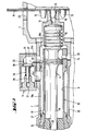
- FIG. 2 shows an enlarged section of a pressed-on, powder-powered setting device before a setting process.
- An axially displaceable housing part 7 with a receptacle 33 is arranged in the housing 1.
- a piston guide 13 with a guide bore 8 for a driving piston 9, which can be displaced from a rear starting position into a front end position on the setting direction by means of propellant gases of a propellant charge 12.
- the piston guide 13 is axially fixed in the receptacle 33.
- the receptacle 33 is provided with a passage opening 14 and the piston guide 13 with a passage 20.
- the passage opening 14 and the passage 20 are arranged essentially coaxially and run essentially radially to the longitudinal extent of the piston guide 13 or the housing part 7.
- the guide bore 8 and the interior of the housing part 7 on the cartridge receiving side are connected to the atmosphere in this way.
- the free end of the housing part 7 lying opposite the setting direction is provided with a cartridge receptacle 10 which is connected to the receptacle 33 of the housing part 7 via a bore 11.
- the cartridge receptacle 10 overlaps a propellant charge 12 located in a cartridge.
- the cartridge is arranged on a strip-shaped propellant charge magazine 6 which can be displaced in a guide channel 23 of the housing 1 essentially perpendicular to the longitudinal extent of the housing part 7.
- the axial displacement of the housing part 7 relative to the housing 1 corresponds at least to the height of the cartridge measured in the longitudinal direction of the housing part 7.
- the housing part 7 has a reduced inner diameter which is matched to the cross section of a sealing piston 15 of the driving piston 9 and which essentially corresponds to the diameter of the guide bore 8 of the piston guide 13
- a channel 18a, 18b formed by the piston guide 13 and the receptacle 33 of the housing part 7 is connected to the guide bore 8 via an opening 17 which is arranged in the area of the piston guide 13 on the setting direction.
- the piston guide 13 is supported radially via two guide areas 21, 22 on an inner wall of the receptacle 33. Between the guide regions 21, 22 and in the end region on the cartridge receiving side, the piston guide 13 has a smaller wall thickness, so that on the outside of the piston guide 13 there are two circumferential free spaces which form the channel 18a, 18b and are separated from one another by the guide region 22.
- Both channels 18a, 18b have through bores 24a, 24b running radially to the longitudinal extent of the piston guide 13 and essentially parallel to one another, which open into a check valve 5 arranged on the outside of the receptacle 33 of the housing part 7.
- a flow channel 27 arranged in the check valve 5 is essentially U-shaped and connects both channels 18a, 18b to one another. Inside the check valve 5, the flow channel 27 has a larger cross section on the side facing the channel 18a than on the side facing the channel 18b. In this way, a shoulder 30 is formed which interacts with a sealing cone 29 of a piston 25.
- the piston 25 can be displaced essentially at right angles to the longitudinal axis of the through bores 24a, 24b and is pressed by a spring 26 against the shoulder 30 into a closed position.
- a receiving bore 31 of the check valve 5 receives a shaft 28 of the piston 25 and guides it axially displaceably.
- an elastic damping element 16 is arranged within the piston guide 13, the function of which is to dampen the speed of the propelling piston 9 when it is accelerated with excessive energy.
- a guide opening 32 of the damping element 16 is matched to the diameter of a cylindrical shaft 19 of the drive piston 9.
Landscapes
- Engineering & Computer Science (AREA)
- Chemical & Material Sciences (AREA)
- Combustion & Propulsion (AREA)
- Mechanical Engineering (AREA)
- Portable Nailing Machines And Staplers (AREA)
Abstract
Description
- Die Erfindung betrifft ein pulverkraftbetriebenes Setzgerät mit einer in einer Aufnahme eines Gehäuseteils angeordneten Kolbenführung mit Führungsbohrung für einen Treibkolben, der mittels Treibgasen einer Treibladung von einer hinteren Ausgangsstellung in eine setzrichtungsseitige vordere Endstellung treibbar ist, einem mit einer Kartuschenaufnahme des Gehäuseteils verbundenen, zwischen der Aufnahme des Gehäuseteils und der Kolbenführung vorgesehenen Kanal, der über eine Öffnung in der Kolbenführung in die Führungsbohrung mündet, einer mit der Atmosphäre in Verbindung stehenden Durchtrittsöffnung in der Aufnahme des Gehäusteils und einer im Kanal angeordneten Ventileinrichtung, die der Bildung eines die setzrichtungsseitigen Bereiche des Kanals und der Führungsbohrung umfassenden, gegenüber der Atmosphäre geschlossenen Speicherraumes dient.
- Aus der DE-OS 43 13 504 ist ein pulverkraftbetriebenes Setzgerät mit einem Gehäuseteil, einer relativ zu einer Aufnahme des Gehäuseteils verschiebbaren Kolbenführung mit einer Führungsbohrung für einen Treibkolben und einem mit einer Kartuschenaufnahme in Verbindung stehenden Kanal bekannt. Dieser Kanal wird von der Kolbenführung und der in radialem Abstand die Kolbenführung umgebenden Aufnahme des Gehäuseteils gebildet. Über eine Öffnung in der Kolbenführung. steht der Kanal mit der Führungsbohrung in Verbindung. Im kartuschenaufnahmeseitigen Bereich des Kanals befindet sich eine Ventileinrichtung, dle der Bildung eines die setzrichtungsseitigen Bereiche des Kanals und der Führungsbohrung umfassenden, gegenüber der Atmosphäre geschlossenen Speicherraumes dient. Die Ventileinrichtung wird von einer Durchmessererweiterung der Kolbenführung und einer Querschnittsverengung der Aufnahme des Gehäuseteils innerhalb des Kanals gebildet. Bei einer Relatiwerschiebung der Kolbenführung gegenüber der Aufnahme des Gehäuseteils wird der Kanal verschlossen oder geöffnet.
- Zum Verschliessen des Kanals erfolgt eine Verschiebung der Kolbenführung gegenüber der Aufnahme des Gehäuseteils in Setzrichtung. Das Volumen des Kanals bzw. des Speicherraumes wird dabei vergrössert, so dass sich der Druck der komprimierten Treibgase verringert. Mit dem reduzierten Treibgasdruck im Speicherraum kann der Treibkolben nur mit einer langsamen Geschwindigkeit in seine Ausgangsstellung zurückversetzt werden. Insbesondere bei einer schnellen Setzfolge von Befestigungselementen kann die Gefahr bestehen, dass der nachfolgende Setzvorgang eingeleitet wird, bevor der Treibkolben seine Ausgangsstellung erreicht hat.
- Der Erfindung liegt die Aufgabe zugrunde, ein pulverkraftbetriebenes Setzgerät zu schaffen, das in seinem Aufbau einfach und störunanfällig ist und eine unter Ausnutzung der Treibgase wirkende Kolbenrückführung aufweist, die eine sichere und schnelle Zurückversetzung des Treibkolbens in seine Ausgangsstellung auch bei einer schnellen Setzfolge gewährleistet.
- Erfindungsgemäss wird die Aufgabe dadurch gelöst, dass die Kolbenführung im kartuschenaufnahmeseitigen Bereich einen vom Treibkolben verschliessbaren, mit der Durchtrittsöffnung in Verbindung stehenden Durchlass aufweist und die Ventileinrichtung als ein durch die Treibgase im Speicherraum schliessendes Rückschlagventil ausgebildet ist.
- Der Einsatz eines durch die Treibgase im Speicherraum schliessenden Rückschlagventils ermöglicht die Schaffung eines Kanals bzw. eines Speicherraumes mit konstantem Volumen. Der sich in dem Speicherraum aufbauende Treibgasdruck bleibt beim Verschliessen des Kanals konstant. Wenn der Treibkolben in Setzrichtung beschleunigt wird, gibt der Treibkolben den Durchlass frei. Über den Durchlass und die Durchtrittsöffnung können die restlichen Treibgase, die sich im kartuschenaufnahmeseitigen Bereich der Führungsbohrung und/oder des Gehäuseteils befinden, an die Atmosphäre gelangen.
- Vorzugsweise ist das Rückschlagventil von den, der Kartuschenaufnahme entströmenden Treibgasen gegen die Kraft einer Feder in eine Öffnungsstellung versetzbar. Wenn der Treibgasdruck der von der Kartuschenaufnahme entströmenden Treibgase kleiner ist als der Druck der in dem Speicherraum befindlichen Treibgase und der Kraft der Feder, wird mit Hilfe der Feder ein schnelles Verschliessen des Kanals erreicht.
- Beispielsweise wirkt eine Feder auf einen Kolben, der von jenen Treibgasen, die von der Kartuschenaufnahme ausgehen, in eine Öffnungsstelllung versetzbar ist.
- Beim Zünden einer Treibladung entsteht Treibgas. Neben dem Treibgas fallen auch Russpartikel und Weine Mengen von unverbranntem Pulver an, die sich insbesondere an jenen Teilen, die in direktem Kontakt mit den Treibgasen stehen, ablagern. Diese Ablagerungen können zu Funktionsstörungen des Setzgerätes führen. Beispielsweise kann es zu Ablagerungen im Bereich des Kolbens des Rückschlagventils kommen, so dass der Kolben den Kanal bzw. den Speicherraum nicht mehr einwandfrei abschliesst. Es ist daher notwendig, die einer starken Ablagerung unterliegenden Teile des Setzgerätes von Zeit zu Zeit zu reinigen, oder zu ersetzen. Damit insbesondere das Entfernen, bzw. Austauschen des erfindungsgemässen Rückschlagventils einfach und schnell möglich ist, ist zweckmässigerweise das Rückschlagventil in dem die Kolbenführung umgebenden Bereich der Aufnahme des Gehäuses angeordnet.
- Die Erfindung wird anhand von Zeichnungen, die ein Ausführungsbeispiel wiedergeben, näher erläutert. Es zeigen:
- Fig. 1
- ein erfindungsgemässes, pulverkraftbetriebenes Setzgerät, schematisch dargestellt;
- Fig. 2
- ein vergrösserter Ausschnitt des Setzgerätes gemäss Fig. 1, in geschnittener Darstellung.
- In der Fig. 1 ist ein erfindungsgemässes pulverkraftbetriebenes Setzgerät schematisch dargestellt, das ein Gehäuse 1, ein gegenüber dem Gehäuse 1 axial versetzbares Gehäuseteil 7 mit einer Aufnahme 33, einen Handgriff 2, einen Betätigungsschalter 3, eine Elementeführung 4 im setzrichtungsseitigen Bereich und ein Rückschlagventil 5 aufweist. Ein Treibladungsmagazin 6 ragt aus dem Gehäuse 1. Die Elementeführung 4 dient der Aufnahme und der Führung von nicht dargestellten Befestigungselementen vor und während eines Setzvorganges.
- Die Fig. 2 zeigt einen vergrösserten Ausschnitt eines angepressten, pulverkraftbetriebenen Setzgerätes vor einem Setzvorgang. In dem Gehäuse 1 ist ein axial versetzbares Gehäuseteil 7 mit einer Aufnahme 33 angeordnet.
- In der Aufnahme 33 befindet sich eine Kolbenführung 13 mit einer Führungsbohrung 8 für einen Treibkolben 9, der mittels Treibgasen einer Treibladung 12 von einer hinteren Ausgangsstellung in eine setzrichtungssseitige vordere Endstellung versetzbar ist. Die Kolbenführung 13 ist axial fest in der Aufnahme 33 angeordnet.
- Im kartuschenaufnahmeseitigen Bereich ist die Aufnahme 33 mit einer Durchtrittsöffnung 14 und die Kolbenführung 13 mit einem Durchlass 20 versehen. Die Durchtrittsöffnung 14 und der Durchlass 20 sind im wesentlichen koaxial angeordnet und verlaufen im wesentlichen radial zur Längserstreckung der Kolbenführung 13 bzw. des Gehäuseteiles 7. Die Führungsbohrung 8 und der kartuschenaufnahmeseitige Innenraum des Gehäuseteils 7 werden auf diese Weise mit der Atmosphäre verbunden.
- Das entgegen der Setzrichtung liegende freie Ende des Gehäuseteiles 7 ist mit einer Kartuschenaufnahme 10 versehen, die über eine Bohrung 11 mit der Aufnahme 33 des Gehäuseteils 7 verbunden ist. Die Kartuschenaufnahme 10 übergreift in der dargestellten, angepressten Stellung eine sich in einer Kartusche befindliche Treibladung 12. Die Kartusche ist an einem streifenförmigen Treibladungsmagazin 6 angeordnet, das in einem Führungskanal 23 des Gehäuses 1 im wesentlichen senkrecht zur Längserstreckung des Gehäuseteiles 7 versetzbar ist. Die axiale Versetzung des Gehäuseteiles 7 gegenüber dem Gehäuse 1 entspricht mindestens der in Längsrichtung des Gehäuseteiles 7 gemessenen Höhe der Kartusche.
- Zwischen der Kartuschenaufnahme 10 und der Durchtrittsöffnung 14 besitzt das Gehäuseteil 7 einen reduzierten, auf den Querschnitt eines Dichtkolbens 15 des Eintreibkolbens 9 abgestimmten lnnendurchmesser auf, der im wesentlichen der Durchmesser der Führungsbohrung 8 der Kolbenführung 13 entspricht
- Über eine Öffnung 17, die im setzrichtungsseitigen Bereich der Kolbenführung 13 angeordnet ist, steht ein von der Kolbenführung 13 und der Aufnahme 33 des Gehäuseteils 7 gebildeter Kanal 18a, 18b mit der Führungsbohrung 8 in Verbindung. Die Kolbenführung 13 stützt sich radial über zwei Führungsbereiche 21, 22 an einer Innenwandung der Aufnahme 33 ab. Zwischen den Führungsbereichen 21, 22 und im kartuschenaufnahmeseitigen Endbereich weist dle Kolbenführung 13 eine geringere Wandstärke auf, so dass sich auf der Aussenseite der Kolbenführung 13 zwei, den Kanal 18a, 18b bildende, umlaufende Freiräume ergeben, die durch den Führungsbereich 22 voneinander getrennt sind.
- Beide Kanäle 18a, 18b weisen radial zur Längserstreckung der Kolbenführung 13 und im wesentlichen parallel zueinander verlaufende Durchgangsbohrungen 24a, 24b auf, die in ein auf der Aussenseite der Aufnahme 33 des Gehäuseteils 7 angeordnetes Rückschlagventil 5 münden. Ein in dem Rückschlagventil 5 angeordneter Strömungskanal 27 ist im wesentlichen U-förmig ausgebildet und verbindet beide Kanäle 18a, 18b miteinander. Innerhalb des Rückschlagventils 5 weist der Strömungskanal 27 auf der dem Kanal 18a zugewandten Seite einen grösseren Querschnitt auf als der dem Kanal 18b zugewandten Seite. Auf diese Weise wird eine Schulter 30 gebildet, die mit einem Dichtkegel 29 eines Kolbens 25 zusammenwirkt.
- Der Kolben 25 ist im wesentlichen rechtwinklig zur Längsachse der Durchgangsbohrungen 24a, 24b versetzbar und wird von einer Feder 26 gegen die Schulter 30 in eine Schliessstellung gedrückt. Eine Aufnahmebohrung 31 des Rückschlagventils 5 nimmt einen Schaft 28 des Kolbens 25 auf und führt diesen axial versetzbar.
- Im setzrichtungsseitigen Endbereich ist innerhalb der Kolbenführung 13 ein elastisches Dämpfelement 16 angeordnet, dessen Aufgabe es ist, die Geschwindigkeit des Treibkoldens 9 zu dämpfen, wenn dieser mit Überenergie beschleunigt wird. Eine Führungsöffnung 32 des Dämpfelementes 16 ist auf den Durchmesser eines zylindrischen Schaftes 19 des Treibkolbens 9 abgestimmt.
Claims (3)
- Pulverkraftbetriebenes Setzgerät mit einer in einer Aufnahme (33) eines Gehäuseteils (7) angeordneten Kolbenführung (13) mit Führungsbohrung (8) für einen Treibkolben (9), der mittels Treibgasen einer Treibladung von einer hinteren Ausgangsstellung in eine setzrichtungsseitige vordere Endstellung treibbar ist, einem mit einer Kartuschenaufnahme (10) des Gehäuseteils (7) verbundenen, zwischen der Aufnahme (33) des Gehäuseteils (7) und der Kolbenführung (13) vorgesehenen Kanal (18a, 18b), der über eine Öffnung (17) in der Kolbenführung (13) in die Führungsbohrung (8) mündet, einer mit der Atmosphäre in Verbindung stehenden Durchtrittsöffnung (14) in der Aufnahme (33) des Gehäusteils (7) und einer im Kanal (18a, 18b) angeordneten Ventileinrichtung, die der Bildung eines die setzrichtungsseitigen Bereiche des Kanals (18a) und der Führungsbohrung (8) umfassenden, gegenüber der Atmosphäre geschlossenen Speicherraumes dlent, dadurch gekennzeichnet, dass die Kolbenführung (13) im kartuschenaufnahmeseitigen Bereich einen vom Treibkolben (9) verschliessbaren, mit der Durchtrittsöffnung (14) in Verbindung stehenden Durchlass (20) aufweist und die Ventileinrichtung als ein durch die Treibgase im Speicherraum schliessendes Rückschlagventil (5) ausgebildet ist.
- Setzgerät nach Anspruch 1, dadurch gekennzeichnet, dass das Rückschlagventil (5) von den der Kartuschenaufnahme (10) entströmenden Treibgasen gegen die Kraft einer Feder (26) in eine Öffnungsstellung versetzbar ist.
- Setzgerät nach Anspruch 1 oder 2, dadurch gekennzeichnet, dass das Rückschlagventil (5) In dem die Kolbenführung (13) umgebenden Bereich der Aufnahme (33) des Gehäuseteiles (7) angeordnet ist.
Applications Claiming Priority (2)
| Application Number | Priority Date | Filing Date | Title |
|---|---|---|---|
| DE19547859 | 1995-12-21 | ||
| DE19547859A DE19547859A1 (de) | 1995-12-21 | 1995-12-21 | Pulverkraftbetriebenes Setzgerät |
Publications (2)
| Publication Number | Publication Date |
|---|---|
| EP0780195A1 true EP0780195A1 (de) | 1997-06-25 |
| EP0780195B1 EP0780195B1 (de) | 2000-05-03 |
Family
ID=7780828
Family Applications (1)
| Application Number | Title | Priority Date | Filing Date |
|---|---|---|---|
| EP96810713A Expired - Lifetime EP0780195B1 (de) | 1995-12-21 | 1996-10-25 | Pulverkraftbetriebenes Setzgerät mit Rückschlagventil zum Zurückführen des Treibkolbens |
Country Status (8)
| Country | Link |
|---|---|
| US (1) | US5767434A (de) |
| EP (1) | EP0780195B1 (de) |
| JP (1) | JPH09183080A (de) |
| KR (1) | KR100404357B1 (de) |
| CN (1) | CN1061584C (de) |
| AU (1) | AU704410B2 (de) |
| DE (2) | DE19547859A1 (de) |
| TW (1) | TW324678B (de) |
Cited By (1)
| Publication number | Priority date | Publication date | Assignee | Title |
|---|---|---|---|---|
| EP0805002A3 (de) * | 1996-05-03 | 1998-01-14 | Beto-Tornado GmbH | Pulverkraftbetriebenes Bolzensetzgerät |
Families Citing this family (23)
| Publication number | Priority date | Publication date | Assignee | Title |
|---|---|---|---|---|
| US5829660A (en) * | 1995-12-07 | 1998-11-03 | Stanley-Bostitch, Inc. | Automatic-type fastener driving device |
| US6062455A (en) * | 1998-08-06 | 2000-05-16 | Anthony C. Giannuzzi | Cartridge strip magazine for powder-actuated fastener setting tool |
| US6321968B1 (en) * | 1998-09-10 | 2001-11-27 | Senco Products, Inc. | Combustion chamber design for propellant charges and power adjustment means |
| AUPQ420099A0 (en) * | 1999-11-23 | 1999-12-16 | Metal Storm Limited | Driver for power tools |
| US6760452B2 (en) * | 2002-10-24 | 2004-07-06 | Visteon Global Technologies, Inc. | Multi-channel audio signal limiter with shared clip detection |
| DE10253668B4 (de) * | 2002-11-19 | 2015-03-05 | Hilti Aktiengesellschaft | Brennkraftbetriebenes Setzgerät |
| DE10259567A1 (de) * | 2002-12-19 | 2004-07-01 | Hilti Ag | Brennkraftbetriebenes Setzgerät |
| FR2855542B1 (fr) * | 2003-05-26 | 2005-08-05 | Freyssinet Int Stup | Procede de surblocage d'au moins un toron dans un bloc d'ancrage et systeme de surblocage d'au moins un toron dans un bloc d'ancrage |
| DE10360371A1 (de) * | 2003-12-22 | 2005-07-28 | Hilti Ag | Brennkraftbetriebenes Setzgerät |
| ITMI20061022A1 (it) | 2006-05-24 | 2007-11-25 | Remington Arms Co Inc | Arma da fuoco azionata mediante gas |
| US7946214B2 (en) * | 2007-08-29 | 2011-05-24 | Ra Brands, L.L.C. | Gas system for firearms |
| US8250964B2 (en) | 2007-08-29 | 2012-08-28 | Ra Brands, L.L.C. | Gas system for firearms |
| US8109194B2 (en) * | 2009-03-20 | 2012-02-07 | Ra Brands, L.L.C. | Clamped gas block for barrel |
| USD661364S1 (en) | 2010-06-21 | 2012-06-05 | Ra Brands, L.L.C. | Gas block |
| CA2765151A1 (en) * | 2009-06-22 | 2010-12-29 | Ra Brands, L.L.C. | Gas plug retention and removal device |
| US8176837B1 (en) | 2009-10-11 | 2012-05-15 | Jason Stewart Jackson | Firearm operating rod |
| US9261314B1 (en) | 2010-07-19 | 2016-02-16 | Jason Stewart Jackson | Sleeve piston for actuating a firearm bolt carrier |
| US8640598B1 (en) | 2010-07-19 | 2014-02-04 | Jason Stewart Jackson | Sleeve piston for actuating a firearm bolt carrier |
| EP2886257A1 (de) * | 2013-12-18 | 2015-06-24 | HILTI Aktiengesellschaft | Eintreibgerät |
| US9562730B2 (en) | 2014-01-13 | 2017-02-07 | Ra Brands, L.L.C. | Replaceable feed ramp |
| EP2923797A1 (de) * | 2014-03-28 | 2015-09-30 | HILTI Aktiengesellschaft | Pyrotechnisches Eintreibgerät |
| EP3184252A1 (de) * | 2015-12-22 | 2017-06-28 | HILTI Aktiengesellschaft | Brennkraftbetriebenes setzgerät und verfahren zum betreiben eines derartigen setzgeräts |
| CN114952728B (zh) * | 2021-02-26 | 2025-06-27 | 台州市大江实业有限公司 | 一种射钉枪及其气缸单元 |
Citations (6)
| Publication number | Priority date | Publication date | Assignee | Title |
|---|---|---|---|---|
| US3744240A (en) * | 1971-11-05 | 1973-07-10 | Olin Corp | Fastener driving tool |
| GB2171351A (en) * | 1985-02-27 | 1986-08-28 | Tench Main Limited | Fastener dispensing and affixing device |
| EP0223740A2 (de) * | 1985-11-19 | 1987-05-27 | HILTI Aktiengesellschaft | Pulverkraftbetriebenes Bolzensetzgerät |
| EP0467835A2 (de) * | 1990-07-17 | 1992-01-22 | HILTI Aktiengesellschaft | Pulverkraftbetriebenes Setzgerät |
| DE4313504A1 (de) | 1993-04-24 | 1994-10-27 | Hilti Ag | Pulverkraftbetriebenes Setzgerät |
| JPH0825246A (ja) * | 1994-07-18 | 1996-01-30 | Kanematsu Nnk Corp | 空気圧式固着具打込機 |
Family Cites Families (3)
| Publication number | Priority date | Publication date | Assignee | Title |
|---|---|---|---|---|
| NL109762C (de) * | 1961-02-02 | |||
| US3645091A (en) * | 1970-08-17 | 1972-02-29 | Valery Vasilievich Ivanov | Gun-type device for mechanical assembly work utilizing energy of explosion |
| US4655380A (en) * | 1983-05-24 | 1987-04-07 | Pneutek, Inc. | Powder-actuated fastener-driving tool |
-
1995
- 1995-12-21 DE DE19547859A patent/DE19547859A1/de not_active Withdrawn
-
1996
- 1996-10-25 EP EP96810713A patent/EP0780195B1/de not_active Expired - Lifetime
- 1996-10-25 DE DE59605124T patent/DE59605124D1/de not_active Expired - Lifetime
- 1996-11-05 TW TW085113473A patent/TW324678B/zh active
- 1996-12-09 US US08/762,174 patent/US5767434A/en not_active Expired - Lifetime
- 1996-12-10 KR KR1019960063832A patent/KR100404357B1/ko not_active Expired - Fee Related
- 1996-12-18 AU AU75447/96A patent/AU704410B2/en not_active Ceased
- 1996-12-19 CN CN96123287A patent/CN1061584C/zh not_active Expired - Fee Related
- 1996-12-24 JP JP8343724A patent/JPH09183080A/ja active Pending
Patent Citations (6)
| Publication number | Priority date | Publication date | Assignee | Title |
|---|---|---|---|---|
| US3744240A (en) * | 1971-11-05 | 1973-07-10 | Olin Corp | Fastener driving tool |
| GB2171351A (en) * | 1985-02-27 | 1986-08-28 | Tench Main Limited | Fastener dispensing and affixing device |
| EP0223740A2 (de) * | 1985-11-19 | 1987-05-27 | HILTI Aktiengesellschaft | Pulverkraftbetriebenes Bolzensetzgerät |
| EP0467835A2 (de) * | 1990-07-17 | 1992-01-22 | HILTI Aktiengesellschaft | Pulverkraftbetriebenes Setzgerät |
| DE4313504A1 (de) | 1993-04-24 | 1994-10-27 | Hilti Ag | Pulverkraftbetriebenes Setzgerät |
| JPH0825246A (ja) * | 1994-07-18 | 1996-01-30 | Kanematsu Nnk Corp | 空気圧式固着具打込機 |
Non-Patent Citations (1)
| Title |
|---|
| PATENT ABSTRACTS OF JAPAN vol. 096, no. 005 31 May 1996 (1996-05-31) * |
Cited By (2)
| Publication number | Priority date | Publication date | Assignee | Title |
|---|---|---|---|---|
| EP0805002A3 (de) * | 1996-05-03 | 1998-01-14 | Beto-Tornado GmbH | Pulverkraftbetriebenes Bolzensetzgerät |
| US6123242A (en) * | 1996-05-03 | 2000-09-26 | Berner Gmbh | Explosive powder charge operated bolt-setting tool |
Also Published As
| Publication number | Publication date |
|---|---|
| CN1061584C (zh) | 2001-02-07 |
| DE59605124D1 (de) | 2000-06-08 |
| KR970033613A (ko) | 1997-07-22 |
| AU704410B2 (en) | 1999-04-22 |
| AU7544796A (en) | 1997-06-26 |
| EP0780195B1 (de) | 2000-05-03 |
| JPH09183080A (ja) | 1997-07-15 |
| TW324678B (en) | 1998-01-11 |
| US5767434A (en) | 1998-06-16 |
| DE19547859A1 (de) | 1997-06-26 |
| KR100404357B1 (ko) | 2004-03-09 |
| CN1159379A (zh) | 1997-09-17 |
Similar Documents
| Publication | Publication Date | Title |
|---|---|---|
| EP0780195A1 (de) | Pulverkraftbetriebenes Setzgerät mit Rückschlagventil zum Zurückführen des Treibkolbens | |
| DE3119956C2 (de) | Schallgedämpftes Eintreibgerät für Befestigungsmittel | |
| DE3037773C2 (de) | ||
| DE4227065C2 (de) | Hydropneumatischer Hammer | |
| EP0805002B1 (de) | Pulverkraftbetriebenes Bolzensetzgerät | |
| EP0888851A2 (de) | Bohr- und/oder Meisselgerät | |
| DE3835788A1 (de) | Schnellschaltendes kugelventil | |
| DE3140144C2 (de) | ||
| EP0467834B1 (de) | Pulverkraftbetriebenes Setzgerät | |
| EP0720893B1 (de) | Pulverkraftbetriebenes Bolzensetzgerät | |
| DE3418238A1 (de) | Pulverkraftbetriebenes setzgeraet | |
| EP1399297B1 (de) | Druckmittelbetriebene austreibvorrichtung | |
| DE102020108231A1 (de) | Verschluss-Vorrichtung mit integriertem linear beweglichen Schlagbolzen-Impulsgeber | |
| EP0805003B1 (de) | Pulverkraftbetriebenes Bolzensetzgerät | |
| EP0267177A1 (de) | Kraftstoffeinspritzdüse | |
| DE4010517B4 (de) | Gasbetriebenes Arbeitsgerät | |
| DE4200910C2 (de) | Automatgetriebe, insbesondere für Kraftfahrzeuge | |
| EP1712870A2 (de) | Druckgasbetriebene Schusswaffe | |
| DE2442545C2 (de) | Rohrverbindungsvorrichtung für Rohrabzweigungen | |
| EP0972615B1 (de) | Pulverkraftbetriebenes Setzgerät | |
| DE2535106A1 (de) | Pneumatisches schlagwerkzeug, insbesondere meisselhammer | |
| DE3936849A1 (de) | Elektrisch angetriebene handwerkzeugmaschine | |
| EP0651174A1 (de) | Regelbarer Schwingungsdämpfer für Kraftfahrzeuge | |
| CH669252A5 (de) | Schliessvorrichtung an einer automatischen rohrwaffe. | |
| WO1989002514A1 (fr) | Vibrateur pneumatique lineaire |
Legal Events
| Date | Code | Title | Description |
|---|---|---|---|
| PUAI | Public reference made under article 153(3) epc to a published international application that has entered the european phase |
Free format text: ORIGINAL CODE: 0009012 |
|
| AK | Designated contracting states |
Kind code of ref document: A1 Designated state(s): DE FR GB SE |
|
| 17P | Request for examination filed |
Effective date: 19971229 |
|
| GRAG | Despatch of communication of intention to grant |
Free format text: ORIGINAL CODE: EPIDOS AGRA |
|
| GRAG | Despatch of communication of intention to grant |
Free format text: ORIGINAL CODE: EPIDOS AGRA |
|
| GRAH | Despatch of communication of intention to grant a patent |
Free format text: ORIGINAL CODE: EPIDOS IGRA |
|
| 17Q | First examination report despatched |
Effective date: 19991007 |
|
| GRAH | Despatch of communication of intention to grant a patent |
Free format text: ORIGINAL CODE: EPIDOS IGRA |
|
| GRAA | (expected) grant |
Free format text: ORIGINAL CODE: 0009210 |
|
| AK | Designated contracting states |
Kind code of ref document: B1 Designated state(s): DE FR GB SE |
|
| REF | Corresponds to: |
Ref document number: 59605124 Country of ref document: DE Date of ref document: 20000608 |
|
| ET | Fr: translation filed | ||
| GBT | Gb: translation of ep patent filed (gb section 77(6)(a)/1977) |
Effective date: 20000807 |
|
| PLBE | No opposition filed within time limit |
Free format text: ORIGINAL CODE: 0009261 |
|
| STAA | Information on the status of an ep patent application or granted ep patent |
Free format text: STATUS: NO OPPOSITION FILED WITHIN TIME LIMIT |
|
| 26N | No opposition filed | ||
| PGFP | Annual fee paid to national office [announced via postgrant information from national office to epo] |
Ref country code: SE Payment date: 20011005 Year of fee payment: 6 |
|
| REG | Reference to a national code |
Ref country code: GB Ref legal event code: IF02 |
|
| PG25 | Lapsed in a contracting state [announced via postgrant information from national office to epo] |
Ref country code: SE Free format text: LAPSE BECAUSE OF NON-PAYMENT OF DUE FEES Effective date: 20021026 |
|
| EUG | Se: european patent has lapsed | ||
| PGFP | Annual fee paid to national office [announced via postgrant information from national office to epo] |
Ref country code: GB Payment date: 20051019 Year of fee payment: 10 |
|
| GBPC | Gb: european patent ceased through non-payment of renewal fee |
Effective date: 20061025 |
|
| PG25 | Lapsed in a contracting state [announced via postgrant information from national office to epo] |
Ref country code: GB Free format text: LAPSE BECAUSE OF NON-PAYMENT OF DUE FEES Effective date: 20061025 |
|
| PGFP | Annual fee paid to national office [announced via postgrant information from national office to epo] |
Ref country code: FR Payment date: 20141008 Year of fee payment: 19 Ref country code: DE Payment date: 20141023 Year of fee payment: 19 |
|
| REG | Reference to a national code |
Ref country code: DE Ref legal event code: R119 Ref document number: 59605124 Country of ref document: DE |
|
| PG25 | Lapsed in a contracting state [announced via postgrant information from national office to epo] |
Ref country code: DE Free format text: LAPSE BECAUSE OF NON-PAYMENT OF DUE FEES Effective date: 20160503 |
|
| REG | Reference to a national code |
Ref country code: FR Ref legal event code: ST Effective date: 20160630 |
|
| PG25 | Lapsed in a contracting state [announced via postgrant information from national office to epo] |
Ref country code: FR Free format text: LAPSE BECAUSE OF NON-PAYMENT OF DUE FEES Effective date: 20151102 |