EP0780247A1 - Bandage pneumatique radial - Google Patents
Bandage pneumatique radial Download PDFInfo
- Publication number
- EP0780247A1 EP0780247A1 EP96120691A EP96120691A EP0780247A1 EP 0780247 A1 EP0780247 A1 EP 0780247A1 EP 96120691 A EP96120691 A EP 96120691A EP 96120691 A EP96120691 A EP 96120691A EP 0780247 A1 EP0780247 A1 EP 0780247A1
- Authority
- EP
- European Patent Office
- Prior art keywords
- grooves
- circumferential direction
- tread
- tire according
- groove
- Prior art date
- Legal status (The legal status is an assumption and is not a legal conclusion. Google has not performed a legal analysis and makes no representation as to the accuracy of the status listed.)
- Granted
Links
- 230000005855 radiation Effects 0.000 description 15
- 238000005096 rolling process Methods 0.000 description 5
- 238000001228 spectrum Methods 0.000 description 5
- 239000006096 absorbing agent Substances 0.000 description 4
- 238000013461 design Methods 0.000 description 4
- 230000002349 favourable effect Effects 0.000 description 4
- 239000011324 bead Substances 0.000 description 3
- 238000005259 measurement Methods 0.000 description 3
- 229910000831 Steel Inorganic materials 0.000 description 2
- 230000001427 coherent effect Effects 0.000 description 2
- 230000000694 effects Effects 0.000 description 2
- 239000000835 fiber Substances 0.000 description 2
- 239000010959 steel Substances 0.000 description 2
- 235000004758 Bergkiefer Nutrition 0.000 description 1
- 239000004677 Nylon Substances 0.000 description 1
- 235000010450 Pino mugo Nutrition 0.000 description 1
- 241001136577 Pinus mugo Species 0.000 description 1
- 235000002914 Pinus uncinata Nutrition 0.000 description 1
- 238000010521 absorption reaction Methods 0.000 description 1
- 230000001154 acute effect Effects 0.000 description 1
- 230000003321 amplification Effects 0.000 description 1
- 239000004760 aramid Substances 0.000 description 1
- 229920003235 aromatic polyamide Polymers 0.000 description 1
- 230000015572 biosynthetic process Effects 0.000 description 1
- 238000010276 construction Methods 0.000 description 1
- 230000001419 dependent effect Effects 0.000 description 1
- 230000001066 destructive effect Effects 0.000 description 1
- 238000011161 development Methods 0.000 description 1
- 230000018109 developmental process Effects 0.000 description 1
- 238000010586 diagram Methods 0.000 description 1
- 238000009434 installation Methods 0.000 description 1
- 238000000034 method Methods 0.000 description 1
- 238000003199 nucleic acid amplification method Methods 0.000 description 1
- 229920001778 nylon Polymers 0.000 description 1
- 229920000728 polyester Polymers 0.000 description 1
- 239000011148 porous material Substances 0.000 description 1
- 230000003014 reinforcing effect Effects 0.000 description 1
- 239000005871 repellent Substances 0.000 description 1
- 238000012360 testing method Methods 0.000 description 1
Images


Classifications
-
- B—PERFORMING OPERATIONS; TRANSPORTING
- B60—VEHICLES IN GENERAL
- B60C—VEHICLE TYRES; TYRE INFLATION; TYRE CHANGING; CONNECTING VALVES TO INFLATABLE ELASTIC BODIES IN GENERAL; DEVICES OR ARRANGEMENTS RELATED TO TYRES
- B60C11/00—Tyre tread bands; Tread patterns; Anti-skid inserts
- B60C11/03—Tread patterns
- B60C11/0302—Tread patterns directional pattern, i.e. with main rolling direction
-
- B—PERFORMING OPERATIONS; TRANSPORTING
- B60—VEHICLES IN GENERAL
- B60C—VEHICLE TYRES; TYRE INFLATION; TYRE CHANGING; CONNECTING VALVES TO INFLATABLE ELASTIC BODIES IN GENERAL; DEVICES OR ARRANGEMENTS RELATED TO TYRES
- B60C11/00—Tyre tread bands; Tread patterns; Anti-skid inserts
- B60C11/03—Tread patterns
- B60C11/0306—Patterns comprising block rows or discontinuous ribs
-
- B—PERFORMING OPERATIONS; TRANSPORTING
- B60—VEHICLES IN GENERAL
- B60C—VEHICLE TYRES; TYRE INFLATION; TYRE CHANGING; CONNECTING VALVES TO INFLATABLE ELASTIC BODIES IN GENERAL; DEVICES OR ARRANGEMENTS RELATED TO TYRES
- B60C11/00—Tyre tread bands; Tread patterns; Anti-skid inserts
- B60C11/03—Tread patterns
- B60C2011/0337—Tread patterns characterised by particular design features of the pattern
- B60C2011/0339—Grooves
- B60C2011/0374—Slant grooves, i.e. having an angle of about 5 to 35 degrees to the equatorial plane
Definitions
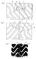
- the present invention relates to a radial tire, in particular for the drive wheels of lorries or buses, with a tread pattern which, as main grooves, has grooves which are inclined with respect to the circumferential direction and at least substantially parallel to one another.
- Fig. 1 shows the scaled-down pint print of a typical traction profile of a truck tire known from the prior art. This profile has four rows of blocks, the blocks having an approximately V-shaped basic shape due to the formation of wide grooves 20 which run obliquely across the tread, as well as narrow grooves 21 running in the same direction and narrow grooves 22 running in opposite directions.
- a truck tire is also known from Austrian Patent No.
- the tread pattern of which is optimized with regard to traction and longitudinal guidance and essentially consists of a central row of blocks running along the tire equator line, two middle and two rows of blocks running on the shoulder, which are arranged in the circumferential direction running grooves are separated from each other.
- DE-A 4 402 699 by the applicant also discloses a device which is preferably to be attached to the wheel arch and which has a system of sound absorbers which is tuned and actively adapted to certain noise components in tires / roadway noise, the frequencies of which change proportionally to the wheel speed can.
- the main grooves either consist of at least two inclined groove sections and a groove section connecting them in the circumferential direction or essentially in the circumferential direction, or an alternating sequence of inclined and circumferential or essentially circumferential directions Assemble groove sections, the angles between the basic direction of extension of the main grooves and the circumferential direction being 30 +/- 20 °, in particular 30 +/- 10 °, when passing through the ground contact area.
- the main grooves run in such a way that when the tire passes through the ground contact surface, the said angle averages as close as possible to 30 ° over a large part of the course of the grooves or is preferably 30 °.
- groove resonances form in profile grooves, which are closed off by contact with the roadway to channels.
- These groove resonances radiate maximum sound energy at one of the frequencies whose associated wavelength corresponds to 2 / (n + 1) multiplied by the length of the channel (n ⁇ 1).
- the energy distribution in the excited resonances depends on the driving speed and the number of blocks, road-dependent parameters, such as roughness and pore volume of the road surface, and specific eigenmodes of the tire structure. Since both open ends of such a channel emit coherently, a spatial interference pattern is formed with radiation directions with constructive interference, which corresponds to sound amplification, and destructive interference, which corresponds to sound cancellation.
- the interference pattern is formed in such a way that the sound radiation occurs mainly in and against the direction of travel, but a greatly reduced sound radiation to the side of the tire.
- the grooves viewed in the tire circumferential direction, are offset from one another, wherein lines which connect kinks or connecting areas of groove sections which are associated with one another at least substantially over the tread width, form an angle of 120 +/- 20 °, in particular 120 Include +/- 10 ° with tire circumferential direction.
- This mutual arrangement of the grooves effectively supports preferred sound radiation in and against the direction of travel and sound radiation significantly reduced to the side of the tire.
- the at least substantially circumferential groove sections have a course which deviates from the circumferential direction by at most 5 °. It is favorable for the reduction of the sound radiation in the lateral direction if the groove sections running essentially in the circumferential direction have an inclination with respect to the circumferential direction which corresponds to the inclination of the other groove sections. In this context, it is also favorable if the length of the inclined groove sections projected onto the circumferential direction is greater than that also projected onto the circumferential direction length of the groove sections running in the circumferential direction or essentially in the circumferential direction.
- the total number of grooves is chosen between 6 and 12, in particular between 8 and 10.
- the number of grooves is advantageously coupled to the tire dimension, which is favorable in order not to negatively influence other profile properties in addition to the sound radiation that can be achieved.
- the tread pattern is designed to be directional, with a profile area having grooves that run in opposite directions to the grooves in a second profile area.
- This allows the advantages of a directional profile design to be combined with the advantages of the present invention.
- it is advantageous if the ends of the grooves coming from the two profile areas, which are located on the inside of the tread, open into at least one central groove. This measure supports the desired coherent and antiphase sound radiation.
- a mutual offset in the circumferential direction of the grooves running in both tread areas is also advantageous in this embodiment variant, since the tire / roadway noise can thereby be influenced overall in a favorable manner.
- FIG. 2 and 3 show plan views of partial developments of two embodiment variants of tread patterns according to the invention, each of which is a basic configuration option, the cutouts shown at least essentially corresponding to the pale impression, dertechnik, Fig. 1a, 2a images of sound field measurements and Fig. 1b, 2b the respectively associated, measured frequency spectra.
- the tread profiles designed according to the invention are intended in particular for drive axle tires of trucks.
- the other structure of the truck tires can in a conventional manner, in particular in addition to the tread, there is a pair of bead areas with bead cores, a pair of side walls, a radial carcass, the free ends of which are led around the bead cores, and a multi-layer belt.
- steel cords are generally suitable, furthermore also organic fibers, such as nylon or polyester, or an aromatic polyamide.
- the belt comprises three to four layers, which in each layer have parallel cords of steel or also organic fiber cord, which run at certain angles with respect to the tire equator.
- the present invention is fundamentally concerned with designing tread patterns for tires in such a way that on the one hand the tire / roadway noise is positively influenced both with regard to sound pressure level and the distribution of the frequencies that occur, on the other hand a largely largely directed in and against the direction of travel (rolling direction) of the tire Sound radiation and a reduction of sound radiation in the lateral direction is supported.
- the tire according to the invention should be usable above all on motor vehicles, especially on trucks or buses, which are provided on the wheel arches with suitable devices for sound absorption.
- the measures taken to achieve this goal will now be explained in more detail using the basic design variants.
- the tread profiles shown in the drawing figures 1 and 2 are each across their width B, that of the width in the ground contact area according to E.T.R.T.O. Standards Manual complies with, considered.
- each groove 1 is composed of an alternating sequence of groove sections 1a and 1b, the groove sections 1a extending in the circumferential direction or at an angle of up to 5 ° and the groove sections 1b at a larger acute angle to the circumferential direction.
- the arrangement or design of the groove sections 1a, 1b is made in such a way that the mean total angles ⁇ of the grooves 1, defined as the angles which, in particular, include straight lines with the circumferential direction (equator line AA) drawn in the basic direction of extent of the grooves 1, and in the mountain pine imprint or while rolling when passing through the ground contact area, 30 +/- 20 °, in particular 30 +/- 10 °, be.
- the length l of the inclined groove sections 1b projected onto a straight line parallel to the circumferential direction should be greater than the likewise determined projected length l 'of the groove sections 1a.
- the grooves 1 thus have a zigzag shape which extends obliquely over the tread, whereby, deviating from this shape, the individual groove sections 1a, 1b can also merge into one another via rounded connecting areas. Any inclination of the groove sections 1a relative to the circumferential direction is preferably selected in the same direction as the inclination of the groove sections 1b.
- each groove 1 passes over a rounded kink into the shoulder areas lying outside the ground contact area.
- the grooves 1 due to their arrangement according to the invention, act like sound sources vibrating in opposite phases in the lateral direction; a spatial interference pattern is generated which, as sound field measurements, which will be discussed in more detail later, confirmed, significantly reduced one on the side of the tire Has sound radiation.
- Tires with such a tread pattern can in particular be fitted with left and right-facing tread grooves 1 as twin tires. However, it is also possible to arrange such tires on the vehicle in such a way that they are mounted as single or twin tires with the same inclination of the tread grooves 1 on each side of the vehicle in order to support a tread groove-induced force balance on the vehicle due to the vehicle-related opposite slope of the tread grooves 1.
- the number of grooves 1, viewed in the transverse direction of the tread pattern, is chosen between 6 and 12, in particular between 8 and 10.
- the grooves 1 are preferably designed to have the same width over their course, wherein all the grooves 1 should have the selected width.
- the cross section of the grooves 1 can be U-shaped, V-shaped or the like, asymmetrical or symmetrical.
- At least one circumferential central groove which can be straight, serrated or undulating, can preferably be arranged in the central region of the tread pattern.
- Fig. 3 shows a variant of the embodiment shown in Fig. 2, in which a circumferential groove 2 is arranged in the circumferential direction along the equatorial line AA of the tire and grooves 1 'according to the invention in both tread halves, with the grooves 1' running in one tread half opposite those grooves running in the second tread half are offset circumferentially.
- each tread half therefore run from the respective tread edge to the central circumferential groove 2 grooves 1 ', which, as described above, are composed of groove sections 1'a assigned to the circumferential direction and inclined groove sections 1'b, an embodiment being shown here in which a groove section 1'a is provided for each tread half per groove 1 '.
- the angles ⁇ and ⁇ defined on the basis of the description of FIG.
- the grooves 1 'in the two tread halves are arranged as a mirror image of the equator line AA, furthermore it is possible to dispense with the central groove 2 and, with the mirror-image arrangement of the grooves 1', the grooves 1 'from each tread half each merge into pairs allow.
- the desired effect of coherent, anti-phase sound radiation in certain directions is more evident in an embodiment with a central groove 2.
- the exemplary embodiment shown in FIG. 3 can also be designed asymmetrically, for example by arranging the grooves 1 ′ in one half of the tread at a mutually smaller distance.
- a pitch length variation which is well known from the prior art, can also be carried out.
- fine slit incisions and other, in particular narrow, incisions can be provided.
- 1a, 2a and 1b, 2b illustrate the effectiveness of the present invention on the basis of images of measured sound fields and determined frequency spectra.
- 1a and 2a show in gray-coded, three-dimensional representations the sound intensity or sound power emitted by the tire in the lateral direction, through a plane parallel to the tire running direction, perpendicular to the ground and at a distance of approximately 20 cm from the tire sidewall.
- the measurements were carried out on a drum test bench at a speed of 70 km / h.
- the dimensions of the tire, the rim and the drum on which the tire runs are outlined in the illustrations.
- the line marks on the rectangle enclosing the representations show the measuring grid. At each crossing point of the vertical and horizontal lines connecting these markings, the sound intensity was determined perpendicular to the plane of the drawing and displayed as a gray value.
- the scale at the bottom of the diagrams shows the sound power assigned to each gray level in dB.
- FIG. 1a now shows the extent and type of the sound field measured from the side of a truck tire with a traction profile designed according to the prior art.
- the tire measured had the tread configuration shown in FIG. 1 with a pronounced block structure.
- the sound field of this known tire is clearly spread out with the intensity distribution characterized by the different gray levels.
- the frequency spectrum shown in Fig. 1b shows pronounced peaks in certain frequency ranges and a high sound pressure level.
- FIG. 2a The sound field measured with a tire whose profile was equipped according to FIG. 2 is shown in FIG. 2a.
- the noise radiation in the lateral direction is significantly reduced.
- the recorded frequency spectrum (Fig. 2b) shows less pronounced peaks and a significantly reduced sound power.
Landscapes
- Engineering & Computer Science (AREA)
- Mechanical Engineering (AREA)
- Tires In General (AREA)
- Yarns And Mechanical Finishing Of Yarns Or Ropes (AREA)
- Valve-Gear Or Valve Arrangements (AREA)
- Mechanical Operated Clutches (AREA)
Applications Claiming Priority (2)
| Application Number | Priority Date | Filing Date | Title |
|---|---|---|---|
| DE19548730A DE19548730C2 (de) | 1995-12-23 | 1995-12-23 | Radialreifen für Lastkraftwagen |
| DE19548730 | 1995-12-23 |
Publications (2)
| Publication Number | Publication Date |
|---|---|
| EP0780247A1 true EP0780247A1 (fr) | 1997-06-25 |
| EP0780247B1 EP0780247B1 (fr) | 2001-06-06 |
Family
ID=7781418
Family Applications (1)
| Application Number | Title | Priority Date | Filing Date |
|---|---|---|---|
| EP96120691A Expired - Lifetime EP0780247B1 (fr) | 1995-12-23 | 1996-12-20 | Bandage pneumatique radial |
Country Status (3)
| Country | Link |
|---|---|
| EP (1) | EP0780247B1 (fr) |
| AT (1) | ATE201852T1 (fr) |
| DE (2) | DE19548730C2 (fr) |
Citations (6)
| Publication number | Priority date | Publication date | Assignee | Title |
|---|---|---|---|---|
| US2034811A (en) * | 1935-02-01 | 1936-03-24 | Pennsylvania Rubber Company | Resilient tire |
| EP0062970A1 (fr) * | 1981-03-26 | 1982-10-20 | Dunlop Limited | Bandage pneumatique pour véhicules à deux roues |
| EP0066531A2 (fr) * | 1981-05-29 | 1982-12-08 | The Goodyear Tire & Rubber Company | Bande de roulement pour pneumatiques radiaux de poids lourds |
| JPS5926306A (ja) * | 1982-08-03 | 1984-02-10 | Honda Motor Co Ltd | 車両用タイヤ |
| JPS63212105A (ja) * | 1987-02-27 | 1988-09-05 | Bridgestone Corp | 二輪車用空気入りタイヤ |
| JPH05104909A (ja) * | 1991-10-14 | 1993-04-27 | Sumitomo Rubber Ind Ltd | 空気入りタイヤ |
Family Cites Families (2)
| Publication number | Priority date | Publication date | Assignee | Title |
|---|---|---|---|---|
| GB282181A (en) * | 1926-09-29 | 1927-12-22 | James Boothroyd Parker | Improvements in or relating to covers for pneumatic tyres |
| FR2053873A5 (fr) * | 1969-07-21 | 1971-04-16 | Michelin & Cie |
-
1995
- 1995-12-23 DE DE19548730A patent/DE19548730C2/de not_active Expired - Fee Related
-
1996
- 1996-12-20 AT AT96120691T patent/ATE201852T1/de active
- 1996-12-20 DE DE59607043T patent/DE59607043D1/de not_active Expired - Fee Related
- 1996-12-20 EP EP96120691A patent/EP0780247B1/fr not_active Expired - Lifetime
Patent Citations (6)
| Publication number | Priority date | Publication date | Assignee | Title |
|---|---|---|---|---|
| US2034811A (en) * | 1935-02-01 | 1936-03-24 | Pennsylvania Rubber Company | Resilient tire |
| EP0062970A1 (fr) * | 1981-03-26 | 1982-10-20 | Dunlop Limited | Bandage pneumatique pour véhicules à deux roues |
| EP0066531A2 (fr) * | 1981-05-29 | 1982-12-08 | The Goodyear Tire & Rubber Company | Bande de roulement pour pneumatiques radiaux de poids lourds |
| JPS5926306A (ja) * | 1982-08-03 | 1984-02-10 | Honda Motor Co Ltd | 車両用タイヤ |
| JPS63212105A (ja) * | 1987-02-27 | 1988-09-05 | Bridgestone Corp | 二輪車用空気入りタイヤ |
| JPH05104909A (ja) * | 1991-10-14 | 1993-04-27 | Sumitomo Rubber Ind Ltd | 空気入りタイヤ |
Non-Patent Citations (3)
| Title |
|---|
| PATENT ABSTRACTS OF JAPAN vol. 008, no. 120 (M - 300) 6 June 1984 (1984-06-06) * |
| PATENT ABSTRACTS OF JAPAN vol. 012, no. 490 (M - 779) 21 December 1988 (1988-12-21) * |
| PATENT ABSTRACTS OF JAPAN vol. 017, no. 455 (M - 1466) 20 August 1993 (1993-08-20) * |
Also Published As
| Publication number | Publication date |
|---|---|
| ATE201852T1 (de) | 2001-06-15 |
| DE19548730A1 (de) | 1997-06-26 |
| DE19548730C2 (de) | 2003-05-15 |
| DE59607043D1 (de) | 2001-07-12 |
| EP0780247B1 (fr) | 2001-06-06 |
Similar Documents
| Publication | Publication Date | Title |
|---|---|---|
| DE69503938T2 (de) | Luftreifen | |
| DE69316299T2 (de) | Luftreifen mit verbesserter Nassgriffigkeit | |
| DE60207836T2 (de) | Laufflächenprofil für einen fahrzeugreifen | |
| AT402178B (de) | Laufstreifen für einen fahrzeugluftreifen | |
| DE69401633T2 (de) | Luftreifen | |
| DE3737264A1 (de) | Luftradialreifen | |
| EP0686517A1 (fr) | Bandage pneumatique pour véhicule, comprenant une armature symétrique et un profil asymétrique | |
| DE4410052A1 (de) | Kraftfahrzeug mit hinteren Raupenbändern | |
| DE69601137T2 (de) | Luftreifen | |
| AT394684B (de) | Laufflaechenprofil fuer einen fahrzeugluftreifen | |
| EP0325905B1 (fr) | Dessin de bande de roulement pour bandages pneumatiques | |
| DE19548733C2 (de) | Radialreifen | |
| EP0588781B2 (fr) | Bandage pneumatique pour véhicule | |
| DE19702675C2 (de) | Profil für PKW-Luftreifen | |
| EP0715972A2 (fr) | Bandage pneumatique pour véhicule | |
| DE19548728C1 (de) | Fahrzeug mit Reifen und mit zumindest einer schallabsorbierenden Vorrichtung | |
| DE2948479A1 (de) | Fahrzeugluftreifen | |
| EP0112533B1 (fr) | Profil de surface de roulement pour bandage pneumatique pour neige et boue | |
| EP0780247B1 (fr) | Bandage pneumatique radial | |
| EP0780246B1 (fr) | Bandage pneumatique radial | |
| EP3551475B1 (fr) | Pneumatique de véhicule | |
| DE4007760C2 (de) | Fahrzeugluftreifen | |
| EP0718123B1 (fr) | Bandage pneumatique pour véhicule | |
| AT402385B (de) | Profilierter laufstreifen für einen fahrzeugluftreifen | |
| DE19548734C2 (de) | Radialreifen |
Legal Events
| Date | Code | Title | Description |
|---|---|---|---|
| PUAI | Public reference made under article 153(3) epc to a published international application that has entered the european phase |
Free format text: ORIGINAL CODE: 0009012 |
|
| AK | Designated contracting states |
Kind code of ref document: A1 Designated state(s): AT DE FR GB IT |
|
| 17P | Request for examination filed |
Effective date: 19971229 |
|
| 17Q | First examination report despatched |
Effective date: 19991109 |
|
| GRAG | Despatch of communication of intention to grant |
Free format text: ORIGINAL CODE: EPIDOS AGRA |
|
| GRAG | Despatch of communication of intention to grant |
Free format text: ORIGINAL CODE: EPIDOS AGRA |
|
| GRAH | Despatch of communication of intention to grant a patent |
Free format text: ORIGINAL CODE: EPIDOS IGRA |
|
| GRAH | Despatch of communication of intention to grant a patent |
Free format text: ORIGINAL CODE: EPIDOS IGRA |
|
| GRAA | (expected) grant |
Free format text: ORIGINAL CODE: 0009210 |
|
| AK | Designated contracting states |
Kind code of ref document: B1 Designated state(s): AT DE FR GB IT |
|
| REF | Corresponds to: |
Ref document number: 201852 Country of ref document: AT Date of ref document: 20010615 Kind code of ref document: T |
|
| REF | Corresponds to: |
Ref document number: 59607043 Country of ref document: DE Date of ref document: 20010712 |
|
| ITF | It: translation for a ep patent filed | ||
| GBT | Gb: translation of ep patent filed (gb section 77(6)(a)/1977) |
Effective date: 20010905 |
|
| ET | Fr: translation filed | ||
| REG | Reference to a national code |
Ref country code: GB Ref legal event code: IF02 |
|
| PLBE | No opposition filed within time limit |
Free format text: ORIGINAL CODE: 0009261 |
|
| STAA | Information on the status of an ep patent application or granted ep patent |
Free format text: STATUS: NO OPPOSITION FILED WITHIN TIME LIMIT |
|
| 26N | No opposition filed | ||
| PGFP | Annual fee paid to national office [announced via postgrant information from national office to epo] |
Ref country code: GB Payment date: 20041213 Year of fee payment: 9 |
|
| PG25 | Lapsed in a contracting state [announced via postgrant information from national office to epo] |
Ref country code: IT Free format text: LAPSE BECAUSE OF NON-PAYMENT OF DUE FEES;WARNING: LAPSES OF ITALIAN PATENTS WITH EFFECTIVE DATE BEFORE 2007 MAY HAVE OCCURRED AT ANY TIME BEFORE 2007. THE CORRECT EFFECTIVE DATE MAY BE DIFFERENT FROM THE ONE RECORDED. Effective date: 20051220 Ref country code: GB Free format text: LAPSE BECAUSE OF NON-PAYMENT OF DUE FEES Effective date: 20051220 |
|
| GBPC | Gb: european patent ceased through non-payment of renewal fee |
Effective date: 20051220 |
|
| PGFP | Annual fee paid to national office [announced via postgrant information from national office to epo] |
Ref country code: FR Payment date: 20081212 Year of fee payment: 13 |
|
| PGFP | Annual fee paid to national office [announced via postgrant information from national office to epo] |
Ref country code: DE Payment date: 20081121 Year of fee payment: 13 |
|
| REG | Reference to a national code |
Ref country code: FR Ref legal event code: ST Effective date: 20100831 |
|
| PG25 | Lapsed in a contracting state [announced via postgrant information from national office to epo] |
Ref country code: FR Free format text: LAPSE BECAUSE OF NON-PAYMENT OF DUE FEES Effective date: 20091231 |
|
| PG25 | Lapsed in a contracting state [announced via postgrant information from national office to epo] |
Ref country code: DE Free format text: LAPSE BECAUSE OF NON-PAYMENT OF DUE FEES Effective date: 20100701 |
|
| PGFP | Annual fee paid to national office [announced via postgrant information from national office to epo] |
Ref country code: AT Payment date: 20101214 Year of fee payment: 15 |
|
| REG | Reference to a national code |
Ref country code: AT Ref legal event code: MM01 Ref document number: 201852 Country of ref document: AT Kind code of ref document: T Effective date: 20111220 |
|
| PG25 | Lapsed in a contracting state [announced via postgrant information from national office to epo] |
Ref country code: AT Free format text: LAPSE BECAUSE OF NON-PAYMENT OF DUE FEES Effective date: 20111220 |