EP0780284A1 - Fixation rigide des pièces de construction d'un véhicule automobile et outillage de confection de la fixation - Google Patents
Fixation rigide des pièces de construction d'un véhicule automobile et outillage de confection de la fixation Download PDFInfo
- Publication number
- EP0780284A1 EP0780284A1 EP96117047A EP96117047A EP0780284A1 EP 0780284 A1 EP0780284 A1 EP 0780284A1 EP 96117047 A EP96117047 A EP 96117047A EP 96117047 A EP96117047 A EP 96117047A EP 0780284 A1 EP0780284 A1 EP 0780284A1
- Authority
- EP
- European Patent Office
- Prior art keywords
- component
- connection
- pressure
- tool
- components
- Prior art date
- Legal status (The legal status is an assumption and is not a legal conclusion. Google has not performed a legal analysis and makes no representation as to the accuracy of the status listed.)
- Withdrawn
Links
Images
Classifications
-
- B—PERFORMING OPERATIONS; TRANSPORTING
- B62—LAND VEHICLES FOR TRAVELLING OTHERWISE THAN ON RAILS
- B62D—MOTOR VEHICLES; TRAILERS
- B62D25/00—Superstructure or monocoque structure sub-units; Parts or details thereof not otherwise provided for
- B62D25/04—Door pillars ; windshield pillars
-
- B—PERFORMING OPERATIONS; TRANSPORTING
- B21—MECHANICAL METAL-WORKING WITHOUT ESSENTIALLY REMOVING MATERIAL; PUNCHING METAL
- B21D—WORKING OR PROCESSING OF SHEET METAL OR METAL TUBES, RODS OR PROFILES WITHOUT ESSENTIALLY REMOVING MATERIAL; PUNCHING METAL
- B21D39/00—Application of procedures in order to connect objects or parts, e.g. coating with sheet metal otherwise than by plating; Tube expanders
- B21D39/04—Application of procedures in order to connect objects or parts, e.g. coating with sheet metal otherwise than by plating; Tube expanders of tubes with tubes; of tubes with rods
-
- B—PERFORMING OPERATIONS; TRANSPORTING
- B21—MECHANICAL METAL-WORKING WITHOUT ESSENTIALLY REMOVING MATERIAL; PUNCHING METAL
- B21D—WORKING OR PROCESSING OF SHEET METAL OR METAL TUBES, RODS OR PROFILES WITHOUT ESSENTIALLY REMOVING MATERIAL; PUNCHING METAL
- B21D39/00—Application of procedures in order to connect objects or parts, e.g. coating with sheet metal otherwise than by plating; Tube expanders
- B21D39/08—Tube expanders
- B21D39/20—Tube expanders with mandrels, e.g. expandable
- B21D39/203—Tube expanders with mandrels, e.g. expandable expandable by fluid or elastic material
-
- B—PERFORMING OPERATIONS; TRANSPORTING
- B62—LAND VEHICLES FOR TRAVELLING OTHERWISE THAN ON RAILS
- B62D—MOTOR VEHICLES; TRAILERS
- B62D25/00—Superstructure or monocoque structure sub-units; Parts or details thereof not otherwise provided for
- B62D25/06—Fixed roofs
-
- B—PERFORMING OPERATIONS; TRANSPORTING
- B62—LAND VEHICLES FOR TRAVELLING OTHERWISE THAN ON RAILS
- B62D—MOTOR VEHICLES; TRAILERS
- B62D27/00—Connections between superstructure or understructure sub-units
- B62D27/02—Connections between superstructure or understructure sub-units rigid
- B62D27/023—Assembly of structural joints
-
- Y—GENERAL TAGGING OF NEW TECHNOLOGICAL DEVELOPMENTS; GENERAL TAGGING OF CROSS-SECTIONAL TECHNOLOGIES SPANNING OVER SEVERAL SECTIONS OF THE IPC; TECHNICAL SUBJECTS COVERED BY FORMER USPC CROSS-REFERENCE ART COLLECTIONS [XRACs] AND DIGESTS
- Y10—TECHNICAL SUBJECTS COVERED BY FORMER USPC
- Y10T—TECHNICAL SUBJECTS COVERED BY FORMER US CLASSIFICATION
- Y10T29/00—Metal working
- Y10T29/49—Method of mechanical manufacture
- Y10T29/49616—Structural member making
- Y10T29/49622—Vehicular structural member making
-
- Y—GENERAL TAGGING OF NEW TECHNOLOGICAL DEVELOPMENTS; GENERAL TAGGING OF CROSS-SECTIONAL TECHNOLOGIES SPANNING OVER SEVERAL SECTIONS OF THE IPC; TECHNICAL SUBJECTS COVERED BY FORMER USPC CROSS-REFERENCE ART COLLECTIONS [XRACs] AND DIGESTS
- Y10—TECHNICAL SUBJECTS COVERED BY FORMER USPC
- Y10T—TECHNICAL SUBJECTS COVERED BY FORMER US CLASSIFICATION
- Y10T29/00—Metal working
- Y10T29/49—Method of mechanical manufacture
- Y10T29/49805—Shaping by direct application of fluent pressure
-
- Y—GENERAL TAGGING OF NEW TECHNOLOGICAL DEVELOPMENTS; GENERAL TAGGING OF CROSS-SECTIONAL TECHNOLOGIES SPANNING OVER SEVERAL SECTIONS OF THE IPC; TECHNICAL SUBJECTS COVERED BY FORMER USPC CROSS-REFERENCE ART COLLECTIONS [XRACs] AND DIGESTS
- Y10—TECHNICAL SUBJECTS COVERED BY FORMER USPC
- Y10T—TECHNICAL SUBJECTS COVERED BY FORMER US CLASSIFICATION
- Y10T29/00—Metal working
- Y10T29/49—Method of mechanical manufacture
- Y10T29/49826—Assembling or joining
- Y10T29/49879—Spaced wall tube or receptacle
-
- Y—GENERAL TAGGING OF NEW TECHNOLOGICAL DEVELOPMENTS; GENERAL TAGGING OF CROSS-SECTIONAL TECHNOLOGIES SPANNING OVER SEVERAL SECTIONS OF THE IPC; TECHNICAL SUBJECTS COVERED BY FORMER USPC CROSS-REFERENCE ART COLLECTIONS [XRACs] AND DIGESTS
- Y10—TECHNICAL SUBJECTS COVERED BY FORMER USPC
- Y10T—TECHNICAL SUBJECTS COVERED BY FORMER US CLASSIFICATION
- Y10T29/00—Metal working
- Y10T29/49—Method of mechanical manufacture
- Y10T29/49826—Assembling or joining
- Y10T29/49908—Joining by deforming
- Y10T29/49938—Radially expanding part in cavity, aperture, or hollow body
- Y10T29/4994—Radially expanding internal tube
-
- Y—GENERAL TAGGING OF NEW TECHNOLOGICAL DEVELOPMENTS; GENERAL TAGGING OF CROSS-SECTIONAL TECHNOLOGIES SPANNING OVER SEVERAL SECTIONS OF THE IPC; TECHNICAL SUBJECTS COVERED BY FORMER USPC CROSS-REFERENCE ART COLLECTIONS [XRACs] AND DIGESTS
- Y10—TECHNICAL SUBJECTS COVERED BY FORMER USPC
- Y10T—TECHNICAL SUBJECTS COVERED BY FORMER US CLASSIFICATION
- Y10T29/00—Metal working
- Y10T29/53—Means to assemble or disassemble
- Y10T29/53996—Means to assemble or disassemble by deforming
-
- Y—GENERAL TAGGING OF NEW TECHNOLOGICAL DEVELOPMENTS; GENERAL TAGGING OF CROSS-SECTIONAL TECHNOLOGIES SPANNING OVER SEVERAL SECTIONS OF THE IPC; TECHNICAL SUBJECTS COVERED BY FORMER USPC CROSS-REFERENCE ART COLLECTIONS [XRACs] AND DIGESTS
- Y10—TECHNICAL SUBJECTS COVERED BY FORMER USPC
- Y10T—TECHNICAL SUBJECTS COVERED BY FORMER US CLASSIFICATION
- Y10T403/00—Joints and connections
- Y10T403/22—Joints and connections with fluid pressure responsive component
-
- Y—GENERAL TAGGING OF NEW TECHNOLOGICAL DEVELOPMENTS; GENERAL TAGGING OF CROSS-SECTIONAL TECHNOLOGIES SPANNING OVER SEVERAL SECTIONS OF THE IPC; TECHNICAL SUBJECTS COVERED BY FORMER USPC CROSS-REFERENCE ART COLLECTIONS [XRACs] AND DIGESTS
- Y10—TECHNICAL SUBJECTS COVERED BY FORMER USPC
- Y10T—TECHNICAL SUBJECTS COVERED BY FORMER US CLASSIFICATION
- Y10T403/00—Joints and connections
- Y10T403/49—Member deformed in situ
- Y10T403/4941—Deformation occurs simultaneously with action of separate, diverse function, joint component
-
- Y—GENERAL TAGGING OF NEW TECHNOLOGICAL DEVELOPMENTS; GENERAL TAGGING OF CROSS-SECTIONAL TECHNOLOGIES SPANNING OVER SEVERAL SECTIONS OF THE IPC; TECHNICAL SUBJECTS COVERED BY FORMER USPC CROSS-REFERENCE ART COLLECTIONS [XRACs] AND DIGESTS
- Y10—TECHNICAL SUBJECTS COVERED BY FORMER USPC
- Y10T—TECHNICAL SUBJECTS COVERED BY FORMER US CLASSIFICATION
- Y10T403/00—Joints and connections
- Y10T403/49—Member deformed in situ
- Y10T403/4958—Separate deforming means remains with joint assembly
-
- Y—GENERAL TAGGING OF NEW TECHNOLOGICAL DEVELOPMENTS; GENERAL TAGGING OF CROSS-SECTIONAL TECHNOLOGIES SPANNING OVER SEVERAL SECTIONS OF THE IPC; TECHNICAL SUBJECTS COVERED BY FORMER USPC CROSS-REFERENCE ART COLLECTIONS [XRACs] AND DIGESTS
- Y10—TECHNICAL SUBJECTS COVERED BY FORMER USPC
- Y10T—TECHNICAL SUBJECTS COVERED BY FORMER US CLASSIFICATION
- Y10T403/00—Joints and connections
- Y10T403/55—Member ends joined by inserted section
- Y10T403/557—Expansible section
Definitions
- the invention relates to a rigid connection of components according to the preamble of claim 1 and a tool for producing the connection according to the preamble of claim 7.
- a generic connection or a generic tool is known from DE 39 27 896 A1.
- a connection or a tool for accurately fitting cams to a hollow shaft is described, with the cams and the hollow shaft guided through their threading opening being inserted in a corresponding shape-negative engraving of a forming tool divided into two halves or four quarters in the processing position.
- An elongated, elastically deformable, open-sided container, into which a hydraulic fluid is filled, is introduced into the hollow shaft under pressure.
- the container is supported in the area of one end of the hollow shaft on a support of the tool and at the other end is attached to a mouthpiece of a hydraulic system in a liquid-tight and pressure-tight manner.
- the mouthpiece rests on the forming tool and supports the hollow shaft at this end.
- the mouthpiece designed as a pressure introduction body has a pressure booster piston with which the hydraulic system exerts a high pressure on the pressure fluid via a pressure channel provided in the mouthpiece and opening into the container, whereby the elastically deformable container expands and lies against the inside of the hollow shaft.
- the hydraulic pressure is passed through the container to the hollow shaft, which is thereby expanded radially over its entire length, so that the Cam received a press fit on the hollow shaft due to the increase in circumference.
- the tool designed for the connection of already coated body parts during assembly is complete due to the complex insertion of the components into the tool, the multi-part design of the tool, which requires a large number of operating steps, and the very large space requirement of the tool not suitable.
- connection For the production of the connection is due to the high demands on the uniformity of the expansion of the hollow shaft - i.e. the internal component - whose surface quality must be very high with regard to a sufficient concentricity, a complete enclosure of the components to be connected with the known tool, which is not possible for body parts with reasonable effort.
- the sheet metal parts are generally connected to one another at their joints in the body shop by resistance welding, as can be seen, for example, from DE 33 06 397.
- mechanical connections such as clinching are used, which is shown by DE 37 01 895.
- the body parts are subjected to an anti-corrosion coating after the connection has been made.
- joining processes such as welding and clinching cannot be used, since the coating on the joints is destroyed and the visible side of the body parts as a result of Impressions, warpage and discoloration would be visually impaired.
- the invention has for its object to develop a generic connection and a generic tool for making the connection in such a way that the components can be joined as body parts in a simple manner even after coating during assembly and can be effectively fixed to one another without plastically deforming the outer component and damage the coating and thus visually impair the visible side of the components.
- the object is achieved by the characteristic features specified in claim 1 with regard to the connection and by the characteristic features specified in claim 7 relating to the tool.
- the invention it is possible to obtain a temporarily detachable connection between them during the assembly of components due to the formation of the outer second component with cross-sectional constrictions by simply plugging the components into one another, in which a predetermined position of the components relative to one another is ensured.
- the inner first component is supported on the cross-sectional constrictions, while in the course between these it forms an expansion space with the surrounding outer component, into which it can plastically deform when a high pressure is introduced via a fluid.
- the previously releasable plug-in connection becomes inextricably rigid via the interlocking that is achieved between the components. Because the fluid is held in a flexible hollow body inserted into the inner component, a dry deformation of the inner component is achieved.
- the inner component which is easier to deform than the outer component due to the much lower yield stress, can plastically deform under the high pressure of the fluid, whereas outer component remains undeformed or at most deforms elastically.
- the deformation concentrates solely on the inner component, so that the outer component, in particular its Visible side is protected from deformation and therefore has no unsightly humps. Spalling of the coating, for example the painting and / or the corrosion protection, is also avoided.
- the tool used to fix the two components to one another which is designed as a flexurally elastic, radially flexible hollow rod, can be introduced into any bending shape of components under an internal fluid pressure that is above atmospheric pressure, whereby it follows the course of the component through its fluidic adapts generated bending elasticity.
- the inserted tool can be inserted more or less far into the component, depending on the location at which an expansion space of the outer component is located.
- traction means are provided which are in the axial direction counteract.
- the inflatable body is sealed pressure-tight on all sides and completely closes the inner component at its ends, so that when a high-pressure fluid is applied, there is no blister of the elastic inflatable body pressing between the inner and the outer component, which may burst, whereupon a rapid pressure drop occurs the high pressure liquid.
- the forming is carried out with very little equipment, since an external support for the external component as well as the press table and press ram used to the internal high-pressure forming due to the special design and the material properties of the external component on the one hand and the largely free deformability of the internal component, i.e. the lack of increased demands on the surface quality and the shape of the inner component are completely eliminated.
- the tool used here for internal high-pressure forming is not fixed in place, but can be handled locally or independently, if necessary, using an assembly robot. Due to the possibility acquired with the connection according to the invention, shortly before completion of the vehicle with finished and coated components to introduce changes for the body of the motor vehicle, the various fashion variants can be built quickly and quickly without reducing quality.
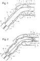
- FIG. 1 shows a section of a roof 1 of a motor vehicle which forms one of the body parts to be joined and which is hollow at least in its front end region 2 and there on the inside two opposite U-shaped stiffening profiles 3 which extend transversely to the roof 1 having. These are arranged with their opening 4 aligned with each other and are welded to the bottom 5 with the inside 6 of the corrosion-resistant coated roof 1 above and below. Alternatively, an adhesive connection is also conceivable.
- the stiffening profiles 3 each have on their legs 7 flange strips 8, between which a tubular first component 9 is inserted, which is welded to the strips 8 at its contact points.
- an adhesive connection is also possible.
- the welding means with the stiffening profiles 3 and thus the rigid connection to the roof 1 for the subsequent high pressure application and expansion of the component 9, a tie rod in the axial direction, which largely prevents the component 9 from axially contracting when it is partially expanded radially.
- the tubular component 9 is curved, being composed of a horizontally lying linear section 10 and a section 11 which bends downwards and forwards at an obtuse angle.
- a second hollow, elongated component 12 which represents the A-pillar of the body and is coated in a corrosion-resistant manner, is slipped onto the section 11 to such an extent that it projects somewhat into an opening 13 in the front end face 14 of the roof 1.
- the second component 12 has two axially spaced cross-sectional constrictions in the connection region 15 to the roof 1, which are designed as constrictions 18 of the linear profile of the component 12 and via which the second component 12 on the inside of the first component 9 frictionally in the detachable plug connection is held.
- the frictional plug connection ensures that the components 9, 12 are securely mounted on the roof 1, preventing the components 9, 12 that are dimensionally matched to one another in the relative position from slipping.
- the component 12 is made from two half-shells 16, 17, which can be pushed onto the component 9 as a prefabricated, welded structural unit.
- the half-shells 16, 17 can also be placed separately on the component 9 and only then welded together. This avoids the cumbersome pushing of the component 12 onto the component 9, in particular when the end cross sections are almost the same size.
- the component 9 has a much lower yield stress than the surrounding component 12 and is therefore considerably easier to deform. If necessary, the wall thickness of the component 9 can also be less than that of the component 12.
- the material of the component 9 can additionally be softer than that of the component 12, so that the deformability of the component 9 with respect to the component 12 is thereby increased.
- This also applies in the comparison of the component 9 with the stiffening profiles 3. This prevents the component 12 from being plastically deformed when the component 9 is subsequently expanded.
- the use of half shells 16, 17 in component 12 and their application to component 9 and the subsequent welding of the shells prevents undesired deformation of component 9, which consists of a material that is very strong and easily deformable relative to component 12.
- the component 12 delimits an expansion space 19 with the component 9.
- the component 9 further delimits with the end 20 of the constriction 18, which adjoins the upper plug connection points towards the roof 1 and radially protrudes with respect to the constriction 18 Component 12 and the inside 6 of the roof 1, an expansion space 21 and with the stiffening profiles 3rd between their spaced-apart flange strips 8 there is an expansion space 22.
- the two body parts to be connected, the roof 1 and the outer second component 12 can also be painted before the rigid connection is achieved.
- cross-sectional constrictions 18 arranged at the top and bottom of the component 12 cross-sectional constrictions can also be provided on the side of this cross-section - optionally also in the form of constrictions.
- Fig. 2 shows the joined body parts 1 and 12 in a rigid connection with each other.
- a tool is pushed through a through opening which is arranged in the front end region 2 of the roof but is further back with respect to the stiffening profiles 3.
- the tool which works with hydroforming technology, includes a high-pressure fluid line 23, which is connected to a hydraulic system and a correspondingly suitable operating unit. Furthermore, a handle is provided on the tool for improved handling.
- a plug 25 is fastened at one end of the line 23, to which on the side 26 facing away from the line an inflatable body 27 designed as an elastomer tube piece is fastened by means of, for example, a tensionable metal band 28, the stopper 25 closing the inflatable body 27 in a pressure-tight manner.
- the tube piece has a wall thickness of about 1-3 mm.
- the inflatable body 27 can alternatively be designed as a pliable, rubber-like flexible skin cover.
- the plug 25 has a longitudinal bore 29 which leads out of the interior 30 of the inflatable body 27 into the fluid line 23 and thus forms the pressure connection.
- the inflatable body 27 is closed in a pressure-tight manner with a further stopper 31 and is also fastened to this with a metal band 28.
- Both plugs 25 and 31 are mushroom-shaped, the plug 31 with its head 32, however, the cross-section of the tubular component 9 in the region of the connector fills outside the area of the component 9 to be deformed, so that the inflatable body 27 cannot emerge from the end 39 of the component 9 facing away from the roof as a bubble. If the hose has a high wall thickness (3 mm), it is not necessary for the plug 31 to completely fill the cross section of the component 9, since the hose cannot swell through the gap between the component 9 and the plug 31 due to its thickness.
- the inflatable body 27 is now acted upon by the fluid line 23 and the longitudinal bore 29 in the interior 30 with a fluid pressure which sets the inflatable body 27 in a flexurally elastic state so that it can follow its bending profile when inserted into the component 9.
- the plug 25 lies tightly with its shaft 33 near the head on the inside 34 of the component 9 and with the underside 35 of its head 36 on the end face 37 thereof. This prevents any expansion of the inflatable body 27 from the component 9 even at the end 40 facing the roof.
- a steel core 38 is provided for this as a traction device counteracting the elongation, which runs inside the interior 30 of the inflatable body and connects the two plugs 25 and 31 to which it is attached.
- the fluid pressure is then increased, the inflatable body 27 expanding radially and pressing tightly against the inside 34 of the component 9. If the pressure is increased further, the material of the component 9 is pressed into the expansion spaces 19, 21 and 22 between the plug connection points, between the weld connection points of the stiffening profiles 3, and between the upper plug connection point and the weld connection point adjacent to this, due to the pressure-imparting inflatable body 27, until a Form-locking of the component 9 with the component 12 and the stiffening profiles 3 results, which causes the parts to jam. Since the pressure is guided in a closed tool system, the tool works completely without recoil, so that easy manual handling is ensured even at high pressures. The pressure can be introduced in superimposed pressure surges of a duration that is in the millisecond range.
- the wall profile of the component 9 can adapt to the inner contour of the component 12 - as shown - or can lay the wall of the component 9 against the wall of the component 12.
- moisture such as condensation water can collect, which can lead to corrosion on the uncoated inside of component 12 and component 9 over time.
- no airborne sound waves can form, which would be disadvantageous for the body noise.
- the fluid pressure is reduced until the inflatable body 27, which is extremely hard under high pressure, is sufficiently flexible, and is pulled out of the component 9.
- Hollow body parts of all conceivable geometric shapes can thus be connected in a simple manner by means of the connection technology according to the invention.
- the material thicknesses of the components 9, 12, the dimensions of the expansion spaces 19, 21, 22, the consistency of the materials of the components 9, 12 to be joined and the pressure height are to be empirically matched to one another, so that the outer component 12 remains undeformed.
Landscapes
- Engineering & Computer Science (AREA)
- Mechanical Engineering (AREA)
- Chemical & Material Sciences (AREA)
- Combustion & Propulsion (AREA)
- Transportation (AREA)
- Body Structure For Vehicles (AREA)
- Shaping Metal By Deep-Drawing, Or The Like (AREA)
Applications Claiming Priority (2)
| Application Number | Priority Date | Filing Date | Title |
|---|---|---|---|
| DE19548341 | 1995-12-22 | ||
| DE19548341A DE19548341C1 (de) | 1995-12-22 | 1995-12-22 | Starre Verbindung von Bauteilen bei einem Kraftfahrzeug und ein Werkzeug zur Herstellung der Verbindung |
Publications (1)
| Publication Number | Publication Date |
|---|---|
| EP0780284A1 true EP0780284A1 (fr) | 1997-06-25 |
Family
ID=7781160
Family Applications (1)
| Application Number | Title | Priority Date | Filing Date |
|---|---|---|---|
| EP96117047A Withdrawn EP0780284A1 (fr) | 1995-12-22 | 1996-10-24 | Fixation rigide des pièces de construction d'un véhicule automobile et outillage de confection de la fixation |
Country Status (3)
| Country | Link |
|---|---|
| US (3) | US5879099A (fr) |
| EP (1) | EP0780284A1 (fr) |
| DE (1) | DE19548341C1 (fr) |
Cited By (2)
| Publication number | Priority date | Publication date | Assignee | Title |
|---|---|---|---|---|
| US5879099A (en) * | 1995-12-22 | 1999-03-09 | Mercedes-Benz Ag | Rigid connection of structural parts in the case of a motor vehicle and tool and method for establishing the connection |
| DE19740102B4 (de) * | 1997-09-12 | 2006-03-23 | Volkswagen Ag | Hohlkörper aus verschiedenen Materialien |
Families Citing this family (18)
| Publication number | Priority date | Publication date | Assignee | Title |
|---|---|---|---|---|
| GB2328393A (en) * | 1997-08-21 | 1999-02-24 | Rover Group | Securing components together and a structural member so formed |
| DE19810252C2 (de) * | 1998-03-10 | 2003-03-13 | Man Nutzfahrzeuge Ag | Vorrichtung zum Einspannen eines Halterohres und Halterohr für Nutzfahrzeuge |
| GB2340058A (en) * | 1998-07-30 | 2000-02-16 | Rover Group | An apparatus for securing components upon a structural member |
| DE19929957B4 (de) * | 1999-06-29 | 2010-12-30 | Daimler Ag | Fügeverbindung und ein Verfahren zur Herstellung derselben, sowie Lenksäule von Kraftfahrzeugen |
| US6609301B1 (en) * | 1999-09-08 | 2003-08-26 | Magna International Inc. | Reinforced hydroformed members and methods of making the same |
| US6482486B1 (en) * | 2000-03-14 | 2002-11-19 | L&L Products | Heat activated reinforcing sleeve |
| US6505389B2 (en) | 2000-12-19 | 2003-01-14 | F&P Mfg., Inc. | Apparatus and method for forming a tube having an article attached thereto |
| DE102004013511B4 (de) * | 2004-03-19 | 2007-03-01 | Daimlerchrysler Ag | Karosseriesäule |
| DE102005045008A1 (de) * | 2005-09-21 | 2007-03-22 | Volkswagen Ag | Verbundhohlprofil |
| JP4698417B2 (ja) * | 2005-12-28 | 2011-06-08 | 株式会社デンソー | 二重管の製造方法 |
| US7383623B2 (en) * | 2006-04-28 | 2008-06-10 | Kozik Pawel R | Assembly and method for vent installation |
| WO2008122107A1 (fr) * | 2007-04-06 | 2008-10-16 | Magna International Inc. | Manchon intérieur de réduction de contrainte pour barre de torsion et procédé associé |
| US7950445B2 (en) * | 2007-07-25 | 2011-05-31 | Golden Sun News Techniques Co., Ltd. | Combined assembly of fixing base and heat pipe |
| FR2921038B1 (fr) * | 2007-09-19 | 2010-01-01 | Peugeot Citroen Automobiles Sa | Structure de carrosserie de vehicule a jonction renforcee entre la traverse avant de pavillon et la doublure du montant de baie de pare-brise |
| ATE498798T1 (de) * | 2008-10-14 | 2011-03-15 | Balcke Duerr Gmbh | Stopfen zum dichten verschliessen eines rohres |
| KR101600296B1 (ko) * | 2010-08-18 | 2016-03-07 | 한온시스템 주식회사 | 이중관식 열교환기 및 그 제조방법 |
| US9713980B2 (en) * | 2015-11-17 | 2017-07-25 | Ford Global Technologies, Llc | Body structure pillar reinforcement for spotlight shaft |
| JP7115354B2 (ja) * | 2019-02-15 | 2022-08-09 | トヨタ自動車株式会社 | ステアリングサポートの固定方法及び固定装置、インストルメントパネルリインフォースメント本体の変形確認方法 |
Citations (7)
| Publication number | Priority date | Publication date | Assignee | Title |
|---|---|---|---|---|
| DE108559C (fr) * | ||||
| GB928912A (en) * | 1959-05-06 | 1963-06-19 | Albert Stulz | Improvements in connections for pipes and tubes |
| FR2345243A1 (fr) * | 1976-03-26 | 1977-10-21 | Combustion Eng | Procede et appareil de fixation d'un manchon tubulaire |
| DE3306397A1 (de) | 1983-02-24 | 1984-02-16 | Daimler-Benz Ag, 7000 Stuttgart | Nacharbeitsstation fuer serienmaessig hergestellte durch widerstands-punktschweissungen zusammengefuegte blechbauteile |
| DE3008840C2 (fr) | 1979-05-25 | 1987-08-13 | Fiat Auto S.P.A., Turin/Torino, It | |
| DE3701895C1 (en) | 1987-01-23 | 1988-03-17 | Audi Ag | Apparatus for joining elements resting flat upon one another, for example metal sheets, by the joggling method |
| DE3927896A1 (de) | 1989-08-24 | 1991-02-28 | Balcke Duerr Ag | Vorrichtung zum lagegenauen befestigen von mehreren teilen auf einem hohlkoerper |
Family Cites Families (40)
| Publication number | Priority date | Publication date | Assignee | Title |
|---|---|---|---|---|
| US605195A (en) * | 1898-06-07 | John birtwisle | ||
| US786551A (en) * | 1901-09-03 | 1905-04-04 | Crane Co | Method of attaching flanges to tubes. |
| US1709865A (en) * | 1927-07-01 | 1929-04-23 | Copeland Products Inc | Process of forming refrigerator elements |
| DE605705C (de) * | 1932-01-03 | 1934-11-16 | Mannesmann Ag | Verbindung von Streben oder Querrahmen mit dem Gurtstab fuer Fachwerk- oder Rahmenkonstruktionen aus Rohrstaeben |
| US2259433A (en) * | 1937-11-15 | 1941-10-14 | Hoover Co | Heat exchanger |
| US2779279A (en) * | 1952-03-08 | 1957-01-29 | Paul S Maiwurm | Apparatus for securing a tube or tubes in a body member |
| US2770874A (en) * | 1953-04-27 | 1956-11-20 | Cleveland Pneumatic Tool Co | Method of locally expanding tubing |
| BE536197A (fr) * | 1954-03-03 | 1900-01-01 | ||
| US2850796A (en) * | 1955-04-27 | 1958-09-09 | Kaplowitz Fred | Methods for cold-working piping, tubing and the like |
| US3104735A (en) * | 1960-11-14 | 1963-09-24 | Arvin Ind Inc | Sound attenuating gas pipe |
| US3243248A (en) * | 1962-06-18 | 1966-03-29 | Speer Frederick | Spring loaded spectacle frame hinge |
| NL297054A (fr) * | 1962-08-23 | 1963-08-23 | ||
| US3206845A (en) * | 1963-01-16 | 1965-09-21 | Joseph R Crump | Apparatus for joining pipe sections |
| US3259206A (en) * | 1964-06-18 | 1966-07-05 | Walker Mfg Co | Exhaust pipe silencer with side branch chambers and baffled elbow sections |
| US3432916A (en) * | 1966-04-18 | 1969-03-18 | Up Right Inc | Method for making a joint for hardened aluminum tubing |
| US3724153A (en) * | 1971-01-19 | 1973-04-03 | Budd Co | Joint construction |
| DE2122350A1 (de) * | 1971-05-06 | 1972-11-16 | Max Langensiepen Kg, 7830 Emmendingen | Dübel, insbesondere aus Kunststoff |
| US3830509A (en) * | 1972-07-14 | 1974-08-20 | Positrol Inc | Hydraulically controlled holding device |
| JPS55141341A (en) * | 1979-04-20 | 1980-11-05 | Kuniyoshi Nakamura | Oscillation type operating rod and its production |
| JPS5916634A (ja) * | 1982-07-19 | 1984-01-27 | Riken Corp | 管状部材と環体部品の結合構造とその結合方法 |
| DE3401057A1 (de) * | 1983-01-14 | 1984-07-19 | Kokan Kako Co., Ltd., Yokohama, Kanagawa | Verfahren zur verbindung eines rohrfoermigen teils mit einem ringfoermigen teil |
| IT1186702B (it) * | 1984-08-07 | 1987-12-16 | Nuovo Pignone Spa | Giunto telescopico perfezionato per la riparazione di tubazioni sottomarine posate a grandi profondita' |
| US4724595A (en) * | 1984-10-04 | 1988-02-16 | Westinghouse Electric Corp. | Bladder mandrel for hydraulic expansions of tubes and sleeves |
| EP0257175B1 (fr) * | 1986-08-12 | 1991-03-27 | Balcke-Dürr AG | Méthode et appareil de fixation de pièces sur un corps creux |
| US5101554A (en) * | 1986-10-01 | 1992-04-07 | Emitec Gesellschaft Fur Emissionstechnologie Mbh | Process for producing an assembled camshaft as well as assembled camshaft consisting of a shaft tube and slid-on elements |
| DE3716986A1 (de) * | 1987-05-21 | 1988-12-15 | Emitec Emissionstechnologie | Vorrichtung zum hydraulischen aufweiten |
| JPH0627512Y2 (ja) * | 1987-11-11 | 1994-07-27 | 新家工業株式会社 | チエーンステーおよびバツクホークとホークエンドとの接続構造 |
| DE3803684A1 (de) * | 1988-02-07 | 1989-08-17 | Emitec Emissionstechnologie | Gebaute getriebewelle |
| FR2630789B1 (fr) * | 1988-04-27 | 1990-08-31 | Charondiere Georges | Dispositif d'assemblage rapide d'elements de raccordement pour des structures, ossatures, supports et autres assemblages |
| US5061000A (en) * | 1989-12-20 | 1991-10-29 | Vix Design Products, Inc. | Rack for pickup truck |
| DE4143528C2 (de) * | 1990-10-23 | 1996-08-29 | Gkn Glaenzer Spicer | Verbindung zwischen einer rohrförmigen Welle aus einem Faserverbundwerkstoff und einem Metallzapfen |
| US5794398A (en) * | 1992-08-25 | 1998-08-18 | Kaehler; Klaus | Framework with hollow members process for producing the same and its use |
| FR2697301B1 (fr) * | 1992-10-23 | 1995-01-13 | Socapex Amphenol | Dispositif de rivet à force d'insertion nulle. |
| JPH0763774B2 (ja) * | 1992-10-30 | 1995-07-12 | 橋田技研工業株式会社 | バルジ成形方法 |
| US5404630A (en) * | 1993-01-22 | 1995-04-11 | Wu; Yung-Yuan | Method of joining a frame tube to a lug |
| EP0662564B2 (fr) * | 1994-01-07 | 2001-09-26 | J. Eberspächer GmbH & Co. | Conduit de gaz d'échappement isolé par une couche d'air et méthode de construction |
| US5479699A (en) * | 1994-02-07 | 1996-01-02 | Westinghouse Electric Corporation | Apparatus for expanding tubular members |
| JPH08241577A (ja) * | 1995-03-03 | 1996-09-17 | Fuji Photo Film Co Ltd | 磁気ディスクカートリッジ |
| DE19510306A1 (de) * | 1995-03-22 | 1996-09-26 | Hilti Ag | Spreizdübel |
| DE19548341C1 (de) * | 1995-12-22 | 1996-12-19 | Daimler Benz Ag | Starre Verbindung von Bauteilen bei einem Kraftfahrzeug und ein Werkzeug zur Herstellung der Verbindung |
-
1995
- 1995-12-22 DE DE19548341A patent/DE19548341C1/de not_active Expired - Fee Related
-
1996
- 1996-10-24 EP EP96117047A patent/EP0780284A1/fr not_active Withdrawn
- 1996-12-03 US US08/758,936 patent/US5879099A/en not_active Expired - Fee Related
-
1998
- 1998-11-04 US US09/185,714 patent/US6122812A/en not_active Expired - Fee Related
- 1998-11-04 US US09/185,715 patent/US6092287A/en not_active Expired - Fee Related
Patent Citations (7)
| Publication number | Priority date | Publication date | Assignee | Title |
|---|---|---|---|---|
| DE108559C (fr) * | ||||
| GB928912A (en) * | 1959-05-06 | 1963-06-19 | Albert Stulz | Improvements in connections for pipes and tubes |
| FR2345243A1 (fr) * | 1976-03-26 | 1977-10-21 | Combustion Eng | Procede et appareil de fixation d'un manchon tubulaire |
| DE3008840C2 (fr) | 1979-05-25 | 1987-08-13 | Fiat Auto S.P.A., Turin/Torino, It | |
| DE3306397A1 (de) | 1983-02-24 | 1984-02-16 | Daimler-Benz Ag, 7000 Stuttgart | Nacharbeitsstation fuer serienmaessig hergestellte durch widerstands-punktschweissungen zusammengefuegte blechbauteile |
| DE3701895C1 (en) | 1987-01-23 | 1988-03-17 | Audi Ag | Apparatus for joining elements resting flat upon one another, for example metal sheets, by the joggling method |
| DE3927896A1 (de) | 1989-08-24 | 1991-02-28 | Balcke Duerr Ag | Vorrichtung zum lagegenauen befestigen von mehreren teilen auf einem hohlkoerper |
Cited By (2)
| Publication number | Priority date | Publication date | Assignee | Title |
|---|---|---|---|---|
| US5879099A (en) * | 1995-12-22 | 1999-03-09 | Mercedes-Benz Ag | Rigid connection of structural parts in the case of a motor vehicle and tool and method for establishing the connection |
| DE19740102B4 (de) * | 1997-09-12 | 2006-03-23 | Volkswagen Ag | Hohlkörper aus verschiedenen Materialien |
Also Published As
| Publication number | Publication date |
|---|---|
| US6122812A (en) | 2000-09-26 |
| US5879099A (en) | 1999-03-09 |
| DE19548341C1 (de) | 1996-12-19 |
| US6092287A (en) | 2000-07-25 |
Similar Documents
| Publication | Publication Date | Title |
|---|---|---|
| DE19548341C1 (de) | Starre Verbindung von Bauteilen bei einem Kraftfahrzeug und ein Werkzeug zur Herstellung der Verbindung | |
| DE102008038276B4 (de) | Verfahren zur Verbindung von Fahrwerksteilen und Fahrwerksbaugruppe | |
| DE69802712T2 (de) | Ein durch innenhochdruck umgeformten bauteil, sowie verfahren und vorrichtung zur dessen herstellung | |
| DE3602499C2 (fr) | ||
| DE102012111936A1 (de) | Stoßdämpfer für ein Fahrzeug mit einem Flansch zur Verbindung eines externen Modulrohres | |
| DE4108741C2 (fr) | ||
| WO2009021838A2 (fr) | Profilé creux partiellement renforcé | |
| DE2016991A1 (fr) | ||
| DE10350145B4 (de) | Erzeugen von IHU-Bauteilen mit Flansch | |
| WO2003008835A1 (fr) | Cuvette de ressort pneumatique et son procede de production | |
| EP2205371B1 (fr) | Procédé pour fabriquer des systèmes à double tube | |
| EP0085388B1 (fr) | Procédé de fabrication d'un manchon métallique à partir d'une pièce tubulaire cylindrique | |
| DE102018131967A1 (de) | Verfahren zum Kalibrieren eines gekrümmten metallischen Hohlkammerprofils | |
| EP1279449A2 (fr) | Méthode et dispositif pour joindre deux objets | |
| DE4425984C2 (de) | Verfahren zum Herstellen eines hohlen Bauteils aus Metall mit in Längsrichtung unterschiedlichen Querschnitten | |
| DE102015206461A1 (de) | Verfahren zur Umformung eines rohrförmigen Strukturbauteils für Kraftfahrzeugsitze | |
| EP1496284A1 (fr) | Serrage passif d'un soufflet d'un ressort pneumaitque où d'un tube | |
| EP2411257B1 (fr) | Boîtier de crémaillère avec rétrécissements de section | |
| DE19941577C2 (de) | Rohrverbindung und Verfahren zu ihrer Herstellung | |
| WO2009068129A1 (fr) | Structure porteuse et procédé de fabrication | |
| DE102013008328A1 (de) | Kupplungshalterung für eine Anhängekupplung | |
| DE19733476C2 (de) | Verfahren zur Herstellung einer montagegerechten Anbringungsstelle an einem Hohlprofil | |
| DE10221880A1 (de) | Verfahren zur Herstellung eines verstärkten Rohres oder Bleches | |
| DE10049047C2 (de) | Verfahren zum Herstellen einer Nockenwelle und danach hergestellte Nockenwelle | |
| DE69322945T2 (de) | Verfahren und Vorrichtung zum Fixieren eines mit zumindest einer zylindrischen Bohrung versehenen metallischen Stückes um ein metallisches Rohr |
Legal Events
| Date | Code | Title | Description |
|---|---|---|---|
| PUAI | Public reference made under article 153(3) epc to a published international application that has entered the european phase |
Free format text: ORIGINAL CODE: 0009012 |
|
| AK | Designated contracting states |
Kind code of ref document: A1 Designated state(s): ES FR GB IT |
|
| 17P | Request for examination filed |
Effective date: 19970517 |
|
| RAP1 | Party data changed (applicant data changed or rights of an application transferred) |
Owner name: DAIMLER-BENZ AKTIENGESELLSCHAFT |
|
| 17Q | First examination report despatched |
Effective date: 19981021 |
|
| RAP1 | Party data changed (applicant data changed or rights of an application transferred) |
Owner name: DAIMLERCHRYSLER AG |
|
| STAA | Information on the status of an ep patent application or granted ep patent |
Free format text: STATUS: THE APPLICATION HAS BEEN WITHDRAWN |
|
| 18W | Application withdrawn |
Withdrawal date: 20001019 |