EP0780336A2 - Handlaufüberwachungssystem - Google Patents
Handlaufüberwachungssystem Download PDFInfo
- Publication number
- EP0780336A2 EP0780336A2 EP96120444A EP96120444A EP0780336A2 EP 0780336 A2 EP0780336 A2 EP 0780336A2 EP 96120444 A EP96120444 A EP 96120444A EP 96120444 A EP96120444 A EP 96120444A EP 0780336 A2 EP0780336 A2 EP 0780336A2
- Authority
- EP
- European Patent Office
- Prior art keywords
- handrail
- current
- monitoring device
- monitor
- conductors
- Prior art date
- Legal status (The legal status is an assumption and is not a legal conclusion. Google has not performed a legal analysis and makes no representation as to the accuracy of the status listed.)
- Granted
Links
Images

Classifications
-
- B—PERFORMING OPERATIONS; TRANSPORTING
- B66—HOISTING; LIFTING; HAULING
- B66B—ELEVATORS; ESCALATORS OR MOVING WALKWAYS
- B66B29/00—Safety devices of escalators or moving walkways
- B66B29/02—Safety devices of escalators or moving walkways responsive to, or preventing, jamming by foreign objects
- B66B29/04—Safety devices of escalators or moving walkways responsive to, or preventing, jamming by foreign objects for balustrades or handrails
-
- B—PERFORMING OPERATIONS; TRANSPORTING
- B66—HOISTING; LIFTING; HAULING
- B66B—ELEVATORS; ESCALATORS OR MOVING WALKWAYS
- B66B23/00—Component parts of escalators or moving walkways
- B66B23/22—Balustrades
- B66B23/24—Handrails
Definitions
- the present invention relates to passenger conveyors, and more particularly to devices for monitoring the condition of a handrail of such a conveyor.
- a typical passenger conveyor such as an escalator or a moving walk, includes a truss, a treadplate assembly driven through a loop by a machine, and a pair of balustrades extending along opposite sides of the treadplate assembly.
- Each balustrade includes a moving handrail that travels at the same speed as the treadplate assembly and enhances the safety and comfort of the passengers riding the conveyor.
- the handrails are formed from a length of non-metallic material that is spliced together to form an endless band.
- the handrails are typically driven by a handrail drive assembly that is connected to the same machine that drives the treadplate assembly.
- Each handrail is tensioned over the outer edges of the balustrade in order to provide sufficient friction for the operation of the handrail drive assembly.
- Tension carriers usually steel wire, are embedded in the handrail to accommodate the tension forces on the handrail.
- the tension carriers may lead to an unacceptable operating condition. If the handrail stretches, the handrail drive assembly may not be able to drive the handrail at the same speed as the treadplate assembly, thus leading to discomfort of the passengers. If the handrail breaks, the handrail drive assembly will only drive the handrail until the point of the break reaches the handrail drive assembly. This will stop the handrail and leave the outer edge of the balustrade exposed.
- Handrail monitoring devices have been used to determine if a failure has occurred in the handrail. These devices typically include a roller mounted on a resilient arm that is urged against the handrail. If a break has occurred, the resilient arm will move and actuate a switch to trigger the conveyor to stop. In addition, the speed of the handrail may be monitored through the rotation of the roller and if the measured speed varies from a predetermined speed, the conveyor may be shut down. A limitation of these types of devices, however, is that they wear over time and this wear may lead to improper operation and unnecessary stopping of the conveyor. In addition, any breaks in the handrail will not be detected until the location of the break reaches the monitoring device. At that point, most of the handrail may have been pulled off of the conveyor.
- a handrail monitoring device includes means for inducing an electrical current in one or more conductors extending through the handrail and means to monitor the induced current.
- Monitoring the induced electrical current provides the advantage of being able to monitor the physical condition of the handrail without direct contact. As a result, wearing of the monitoring device is of less concern. Another advantage is that the induced current will change due to a break or rupture anywhere in the handrail. This break or rupture will be detected immediately by the present invention and the handrail drive may be stopped quickly in response to the detected break or rupture. There is no need for the damaged region of the handrail to have to pass through the monitoring device before the break is detected, as in prior art devices.
- the conductors within the handrail also function as the tension carriers within the handrail.
- This embodiment has the advantage of making use of the tension carriers already present within a typical handrail by electrically closing each tension carrier into a circuit. If any of the tension carriers should fail, the monitoring device would detect the failure and appropriate maintenance may be performed.
- the handrail monitoring device includes a control system and a safety circuit.
- the control system compares the outputs from the monitoring means to a range of acceptable values for the induced current. If the measured current exceeds the range of acceptable values, a relay is triggered to actuate a switch in the safety circuit and thereby shut off the handrail drive.
- a method of monitoring the condition of the handrail includes the following steps: inducing a current in the conductors within the handrail, measuring the induced current, comparing the measured current to a predetermined acceptable range of current, and stopping the handrail if the measured current exceeds the acceptable range.
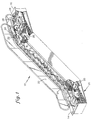
- Fig. 1 is a perspective view of an escalator.
- Fig. 2 is a schematic illustration of a handrail monitoring system according to the invention.
- Fig. 3 is a functional block diagram of a method to monitor a handrail of a passenger conveyor.
- Fig. 4 is a cross-sectional view of a handrail.
- Fig. 1 shows an escalator 10 as an exemplary embodiment of a passenger conveyor, which is used to describe the present invention. It should become apparent in the ensuing description that the invention is applicable to other passenger conveyors having moving handrails, such as moving walks.
- the escalator 10 includes a truss 12 extending between a lower landing 14 and an upper landing 16, a plurality of sequentially connected treadplates 18 connected to a step chain 20 and traveling through a closed loop path within the truss 12, a pair of balustrades 22 having handrails 24, and a machine 26 for driving the treadplates 18 and handrails 24.
- the machine 26 is located in a machine space 28 under the upper landing 16.
- Each balustrade 22 extends along opposite sides of the exposed portion of the treadplate 18 assembly.
- Each handrail 24 is slidingly engaged with the outer edge of the balustrade 22 and is driven through an endless loop by a handrail drive 32.
- the handrail drive 32 is typically driven off the machine 26 for coordinated movement of the handrail 24 with the treadplate 18 assembly. Coordinating the movement of the handrail 24 with the treadplates 18 significantly adds to the comfort of the passengers.
- the handrail 24 is formed from a shaped elastomer material, as shown in Fig. 4. Embedded within the handrail 24 are a plurality of steel reinforcements 34 that extend longitudinally along the entire length of the handrail 24. Each handrail 24 is formed by extruding the elastomer material, with the embedded reinforcements 34, in the desired cross-sectional shape. The extruded structure is then cut to the length required for the specific application and the ends of the cut length of the structure are then spliced together to make the handrail 24. During the splicing process, the individual steel reinforcements 34 are also spliced together to define a plurality of closed loop, electrical conductors.
- the handrail 24 may stretch. Stretching may cause the handrail 24 to move at a different speed than the treadplates 18 and lead to discomfort of the passengers. In extreme situations, the handrail 24 may fail and, if not monitored, the handrail drive 32 will pull the handrail 24 off the balustrade 22. In addition, the handrail 24 will accumulate within the truss 12 and possibly lead to other damage to the escalator 10.
- a handrail monitoring device 36 is incorporated into the escalator 10.
- the handrail monitoring device 36 includes an inducting means 38 and a monitoring means 42, each located at separate points along the path of the handrail 24.
- the inducting means 38 includes a core 44, a coil 46, and a current source 48.
- the core 44 is disposed in the traveling path of the handrail 24 and encompasses a portion of the handrail 24 as it travels through the path.
- the coil 46 is disposed about the core 44 and is electrically connected to the current source 48.
- the core 44, coil 46 and current source 48 define means to induce an electrical current in the steel reinforcements 34 sufficient to be detected by the monitoring means 42. For comfort, the induced current in the reinforcements 34 should be below the level that is perceivable by the passengers holding the handrail 24.
- the monitoring means 42 passively detects the induced current in the steel reinforcements 24.
- the monitoring means includes a core 52, a coil 54, a current sensing device 56, a control unit 58, and a relay 62.
- the core 52 is disposed in the traveling path of the handrail 24 and encompasses a portion of the handrail 24 as it travels through the path.
- the coil 54 is disposed about the core 52 and is electrically connected to the current sensing device 56.
- the current sensing device 56 communicates with the control unit 58.
- the control unit 58 includes the logic for evaluating the signals from the current sensing device 56 and controls the actuation of the relay 62 in response to those signals.
- the relay 62 is incorporated into the safety circuit 64 of the escalator 10 and opens and closes as commanded by the control unit 58.
- the handrail monitoring device 36 continually monitors the condition of the handrail 24 and controls the operation of the escalator 10 in response the perceived condition, as shown in the functional diagram of Fig. 3.
- the current source 48 generates an electrical current in the inducting coil 46, which in conjunction with the inducting core 44 induces an electrical current in the steel reinforcements 34 in the handrail 24.
- This induced current is present throughout the entire length of the handrail 24 and is detected by the monitoring core 52 and coil 54.
- the level of the induced current is determined by the current sensing device 56 and a signal Lm indicative of this measured level is communicated to the control unit 58.
- the measured level Lm is compared to a range of predetermined acceptable levels for the induced current. If the measured level is not within a minimal acceptable range L(Lm>L 3 ), the control unit 58 actuates the relay 62 and the escalator 10 is stopped. If the measured level Lm is within the minimal acceptable range, the relay 62 is not actuated and the operation of the escalator 10 continues.
- the determination of the specific range of acceptable values for the induced current will depend upon the sensitivity required for each specific application. If it is desired to only stop the escalator in the event of a failure of the handrail, i.e., a break somewhere in the handrail, this may be sensed by simply using a predetermined minimum value for the measured induced current. If a failure occurs, the closed loop circuit defined by the reinforcements no longer exists and the inducing means will not be able to induce a current in the reinforcements. Regardless of the location of the failure, this will be sensed immediately by the monitoring means and the handrail drive can be shut off before a significant portion of the handrail is pulled through the handrail drive.
- the minimum threshold for the measured current may be higher. This would permit the escalator to be stopped in the event that the minimum number of reinforcements have failed. For example, if the handrail has six reinforcements and the predetermined minimum number for operation of the escalator is three, the minimum threshold for the measured current may be set to correspond to the level of current induced in only three of the reinforcements. In this way, the handrail may be replaced before a failure of the handrail occurs.
- control logic may be configured to respond differently to different measured levels of induced current, as illustrated in Fig. 3.
- the control unit could provide a signal that the handrail should be inspected; at a second level of degradation (L 3 ⁇ Lm ⁇ L 2 ), another signal could be provided to indicate that the handrail should be replaced; and finally, if a minimum level of measured current is not met (Lm ⁇ L 3 ), the escalator is shut down.
- the embodiment shown in Figs. 1-4 and described above uses the steel reinforcements as the electrical conductors within the handrail.
- This embodiment provides the simplicity of combining the handrail reinforcement and electrical conductor functions into a single element.
- separate electrical conductors may be embedded within the handrail and spliced together to provide the closed loop electrical circuits.
- the functions of handrail reinforcement and electrical conductivity are separated such that the reinforcements may be optimized for their specific function and the electrical conductors may be optimized for their specific function.
Landscapes
- Escalators And Moving Walkways (AREA)
Applications Claiming Priority (2)
| Application Number | Priority Date | Filing Date | Title |
|---|---|---|---|
| US08/574,792 US6015038A (en) | 1995-12-19 | 1995-12-19 | Handrail monitoring system |
| US574792 | 1995-12-19 |
Publications (3)
| Publication Number | Publication Date |
|---|---|
| EP0780336A2 true EP0780336A2 (de) | 1997-06-25 |
| EP0780336A3 EP0780336A3 (de) | 1997-10-15 |
| EP0780336B1 EP0780336B1 (de) | 2002-05-08 |
Family
ID=24297664
Family Applications (1)
| Application Number | Title | Priority Date | Filing Date |
|---|---|---|---|
| EP96120444A Expired - Lifetime EP0780336B1 (de) | 1995-12-19 | 1996-12-18 | Handlaufüberwachungssystem |
Country Status (4)
| Country | Link |
|---|---|
| US (1) | US6015038A (de) |
| EP (1) | EP0780336B1 (de) |
| JP (1) | JPH09202579A (de) |
| DE (1) | DE69621111T2 (de) |
Cited By (3)
| Publication number | Priority date | Publication date | Assignee | Title |
|---|---|---|---|---|
| DE10018410A1 (de) * | 2000-04-13 | 2001-10-25 | Kone Corp | Verfahren und Einrichtung zur Überwachung von Handlauf-Längenänderungen |
| DE10122204A1 (de) * | 2001-05-08 | 2002-11-21 | Otis Elevator Co | Aufzugssicherheitssystem |
| AU2002318615B2 (en) * | 1998-08-20 | 2004-11-18 | Otis Elevator Company | Linear handrail drive |
Families Citing this family (17)
| Publication number | Priority date | Publication date | Assignee | Title |
|---|---|---|---|---|
| US7404477B1 (en) * | 2004-02-26 | 2008-07-29 | Toennisson H Eugene | Proximity hand rail monitor for a moving walkway |
| US7350436B2 (en) * | 2004-03-29 | 2008-04-01 | Shimano, Inc. | Electrical bicycle shift control device |
| US7779724B2 (en) * | 2004-04-19 | 2010-08-24 | Shimano Inc. | Electrical bicycle shift control device |
| GB0517759D0 (en) * | 2005-09-01 | 2005-10-12 | Fenner Dunlop Ltd | Conveyor belt monitoring |
| US8205735B2 (en) * | 2008-06-17 | 2012-06-26 | Intel-Ge Care Innovations Llc | Monitoring handrails to reduce falls |
| JP5457738B2 (ja) * | 2009-06-26 | 2014-04-02 | 三菱電機株式会社 | 手摺駆動制御装置 |
| JP6231442B2 (ja) * | 2014-06-25 | 2017-11-15 | 株式会社日立製作所 | 乗客コンベア |
| DE102015212267A1 (de) * | 2015-07-01 | 2017-01-05 | Voith Patent Gmbh | Verfahren und Vorrichtung zum Bestimmen eines spezifischen Energieverbrauchs von Gurtförderern |
| JP6103019B1 (ja) * | 2015-11-04 | 2017-03-29 | 三菱電機ビルテクノサービス株式会社 | 乗客コンベア用手摺及び測定治具 |
| CN107662871B (zh) | 2016-07-29 | 2021-04-06 | 奥的斯电梯公司 | 用于乘客运输装置的移动扶手监测系统、乘客运输装置及其监测方法 |
| CN108726338A (zh) | 2017-04-19 | 2018-11-02 | 奥的斯电梯公司 | 乘客运输机的扶手的速度检测装置及其速度检测方法 |
| US9994429B1 (en) * | 2017-05-15 | 2018-06-12 | Otis Elevator Company | Handrail with a built-in RBI |
| CN110817673A (zh) * | 2018-08-10 | 2020-02-21 | 奥的斯电梯公司 | 具有安全传感器的自动扶梯系统 |
| CN113454015B (zh) * | 2019-02-28 | 2024-04-26 | 三菱电机株式会社 | 乘客输送机和乘客输送机的移动扶手温度调整方法 |
| WO2021038689A1 (ja) * | 2019-08-26 | 2021-03-04 | 三菱電機株式会社 | 乗客コンベア用の移動手摺装置 |
| EP3812333A1 (de) * | 2019-10-23 | 2021-04-28 | KONE Corporation | Überwachungsanordnung und -verfahren für personenförderer |
| CN113443539B (zh) * | 2020-03-24 | 2024-11-12 | 奥的斯电梯公司 | 扶手安全控制装置、输送系统和扶手安全控制方法 |
Family Cites Families (9)
| Publication number | Priority date | Publication date | Assignee | Title |
|---|---|---|---|---|
| US2649955A (en) * | 1951-09-18 | 1953-08-25 | Goodman Mfg Co | Conveyer belt control |
| US3651506A (en) * | 1969-09-30 | 1972-03-21 | Bergwerksverband Gmbh | Conveyor band monitoring apparatus |
| DE2136347C3 (de) * | 1971-07-21 | 1974-07-11 | Bergwerksverband Gmbh, 4300 Essen | Leiterschleifen für die Überwachung von Stahlseilförderbändern |
| US3899071A (en) * | 1973-06-29 | 1975-08-12 | Walter Roy Duffy | Conveyor belt protective system |
| JPH01114916A (ja) * | 1987-10-29 | 1989-05-08 | Japan Atom Energy Res Inst | 電源装置 |
| JPH0398990A (ja) * | 1989-09-13 | 1991-04-24 | Toshiba Corp | マンコンベアの安全装置 |
| US4982829A (en) * | 1990-01-04 | 1991-01-08 | Otis Elevator Company | Flexible escalator handrail |
| JPH05246676A (ja) * | 1992-03-04 | 1993-09-24 | Toshiba Corp | エスカレータの移動手すり |
| JPH05286681A (ja) * | 1992-04-07 | 1993-11-02 | Hitachi Building Syst Eng & Service Co Ltd | 乗客コンベアの制御装置 |
-
1995
- 1995-12-19 US US08/574,792 patent/US6015038A/en not_active Expired - Fee Related
-
1996
- 1996-12-17 JP JP8336470A patent/JPH09202579A/ja not_active Withdrawn
- 1996-12-18 DE DE69621111T patent/DE69621111T2/de not_active Expired - Lifetime
- 1996-12-18 EP EP96120444A patent/EP0780336B1/de not_active Expired - Lifetime
Cited By (5)
| Publication number | Priority date | Publication date | Assignee | Title |
|---|---|---|---|---|
| AU2002318615B2 (en) * | 1998-08-20 | 2004-11-18 | Otis Elevator Company | Linear handrail drive |
| DE10018410A1 (de) * | 2000-04-13 | 2001-10-25 | Kone Corp | Verfahren und Einrichtung zur Überwachung von Handlauf-Längenänderungen |
| DE10122204A1 (de) * | 2001-05-08 | 2002-11-21 | Otis Elevator Co | Aufzugssicherheitssystem |
| US6591947B2 (en) | 2001-05-08 | 2003-07-15 | Otis Elevator Company | Use of multi-state sensors |
| DE10122204B4 (de) * | 2001-05-08 | 2008-10-09 | Otis Elevator Co., Farmington | Aufzugssicherheitssystem |
Also Published As
| Publication number | Publication date |
|---|---|
| DE69621111T2 (de) | 2002-12-19 |
| US6015038A (en) | 2000-01-18 |
| DE69621111D1 (de) | 2002-06-13 |
| JPH09202579A (ja) | 1997-08-05 |
| EP0780336A3 (de) | 1997-10-15 |
| EP0780336B1 (de) | 2002-05-08 |
Similar Documents
| Publication | Publication Date | Title |
|---|---|---|
| US6015038A (en) | Handrail monitoring system | |
| US7954620B2 (en) | Passenger conveyor handrail drive control strategy | |
| US4145920A (en) | Apparatus for detecting abnormal condition of wire rope | |
| US20040226805A1 (en) | Chain wear monitoring method and apparatus | |
| US20170233222A1 (en) | Elevator | |
| CN1269723C (zh) | 用于监控自动扶梯和移动通道的安全装置及其方法 | |
| US5361887A (en) | Apparatus for detecting an irregularity in the frequency of steps passing a particular point within a passenger conveying device | |
| EP1309510B1 (de) | Verfahren und vorrichtung zur überwachung von kammplattenzähnen für personenbeförderer | |
| TWI843835B (zh) | 用於乘客運輸系統的側邊監視裝置 | |
| CN103387177B (zh) | 乘客运输机的运转控制系统和运转控制方法 | |
| CN109678040B (zh) | 人员输送器和确定用于驱动人员输送器的扶手元件的功率的方法 | |
| JP7781023B2 (ja) | 乗客コンベアおよびその乗り位置誘導装置 | |
| JP4871826B2 (ja) | 乗客コンベアの踏段鎖破断検出装置 | |
| JP2006290502A (ja) | 乗客コンベア | |
| EP2045203A1 (de) | Personenbeförderungseinrichtung | |
| EP4497717A1 (de) | Bremssystem für ein fördersystem und detektionsverfahren und steuerung für die bremse für ein fördersystem | |
| US20250042699A1 (en) | Escalator entrapment detection system | |
| EP4660122A1 (de) | Sicherheitsdetektionsvorrichtung und fahrtreppe oder fahrsteig mit der vorrichtung | |
| EP4509456B1 (de) | Rolltreppenkammplattenretraktionsvorrichtung | |
| CN115210168B (zh) | 人员运送设备和用于运行人员运送设备的方法 | |
| JPH06144766A (ja) | マンコンベアの乗降口安全装置 | |
| JP7080960B1 (ja) | マンコンベアの運転制御システム | |
| JPH05338980A (ja) | マンコンベアの安全装置 | |
| JP2023082423A (ja) | 乗客コンベア | |
| KR19980057285U (ko) | 에스컬레이터의 스텝롤러 이상작동 검출장치 |
Legal Events
| Date | Code | Title | Description |
|---|---|---|---|
| PUAI | Public reference made under article 153(3) epc to a published international application that has entered the european phase |
Free format text: ORIGINAL CODE: 0009012 |
|
| AK | Designated contracting states |
Kind code of ref document: A2 Designated state(s): DE FR GB |
|
| PUAL | Search report despatched |
Free format text: ORIGINAL CODE: 0009013 |
|
| AK | Designated contracting states |
Kind code of ref document: A3 Designated state(s): DE FR GB |
|
| 17P | Request for examination filed |
Effective date: 19980415 |
|
| 17Q | First examination report despatched |
Effective date: 20000803 |
|
| GRAG | Despatch of communication of intention to grant |
Free format text: ORIGINAL CODE: EPIDOS AGRA |
|
| GRAG | Despatch of communication of intention to grant |
Free format text: ORIGINAL CODE: EPIDOS AGRA |
|
| GRAH | Despatch of communication of intention to grant a patent |
Free format text: ORIGINAL CODE: EPIDOS IGRA |
|
| REG | Reference to a national code |
Ref country code: GB Ref legal event code: IF02 |
|
| GRAH | Despatch of communication of intention to grant a patent |
Free format text: ORIGINAL CODE: EPIDOS IGRA |
|
| GRAA | (expected) grant |
Free format text: ORIGINAL CODE: 0009210 |
|
| AK | Designated contracting states |
Kind code of ref document: B1 Designated state(s): DE FR GB |
|
| REF | Corresponds to: |
Ref document number: 69621111 Country of ref document: DE Date of ref document: 20020613 |
|
| ET | Fr: translation filed | ||
| PLBE | No opposition filed within time limit |
Free format text: ORIGINAL CODE: 0009261 |
|
| STAA | Information on the status of an ep patent application or granted ep patent |
Free format text: STATUS: NO OPPOSITION FILED WITHIN TIME LIMIT |
|
| 26N | No opposition filed |
Effective date: 20030211 |
|
| PGFP | Annual fee paid to national office [announced via postgrant information from national office to epo] |
Ref country code: GB Payment date: 20041214 Year of fee payment: 9 |
|
| PGFP | Annual fee paid to national office [announced via postgrant information from national office to epo] |
Ref country code: FR Payment date: 20041217 Year of fee payment: 9 |
|
| PG25 | Lapsed in a contracting state [announced via postgrant information from national office to epo] |
Ref country code: GB Free format text: LAPSE BECAUSE OF NON-PAYMENT OF DUE FEES Effective date: 20051218 |
|
| GBPC | Gb: european patent ceased through non-payment of renewal fee |
Effective date: 20051218 |
|
| PG25 | Lapsed in a contracting state [announced via postgrant information from national office to epo] |
Ref country code: FR Free format text: LAPSE BECAUSE OF NON-PAYMENT OF DUE FEES Effective date: 20060831 |
|
| REG | Reference to a national code |
Ref country code: FR Ref legal event code: ST Effective date: 20060831 |
|
| PGFP | Annual fee paid to national office [announced via postgrant information from national office to epo] |
Ref country code: DE Payment date: 20101215 Year of fee payment: 15 |
|
| REG | Reference to a national code |
Ref country code: DE Ref legal event code: R119 Ref document number: 69621111 Country of ref document: DE Effective date: 20120703 |
|
| PG25 | Lapsed in a contracting state [announced via postgrant information from national office to epo] |
Ref country code: DE Free format text: LAPSE BECAUSE OF NON-PAYMENT OF DUE FEES Effective date: 20120703 |