EP0780503A2 - Verfahren und Vorrichtung zur Herstellung eines fasergefüllten, gepolsterten Kissens - Google Patents
Verfahren und Vorrichtung zur Herstellung eines fasergefüllten, gepolsterten Kissens Download PDFInfo
- Publication number
- EP0780503A2 EP0780503A2 EP96203164A EP96203164A EP0780503A2 EP 0780503 A2 EP0780503 A2 EP 0780503A2 EP 96203164 A EP96203164 A EP 96203164A EP 96203164 A EP96203164 A EP 96203164A EP 0780503 A2 EP0780503 A2 EP 0780503A2
- Authority
- EP
- European Patent Office
- Prior art keywords
- fibers
- mold
- cushion
- cavity
- mixture
- Prior art date
- Legal status (The legal status is an assumption and is not a legal conclusion. Google has not performed a legal analysis and makes no representation as to the accuracy of the status listed.)
- Withdrawn
Links
Images



Classifications
-
- B—PERFORMING OPERATIONS; TRANSPORTING
- B29—WORKING OF PLASTICS; WORKING OF SUBSTANCES IN A PLASTIC STATE IN GENERAL
- B29D—PRODUCING PARTICULAR ARTICLES FROM PLASTICS OR FROM SUBSTANCES IN A PLASTIC STATE
- B29D99/00—Subject matter not provided for in other groups of this subclass
- B29D99/0092—Producing upholstery articles, e.g. cushions, seats
-
- B—PERFORMING OPERATIONS; TRANSPORTING
- B29—WORKING OF PLASTICS; WORKING OF SUBSTANCES IN A PLASTIC STATE IN GENERAL
- B29C—SHAPING OR JOINING OF PLASTICS; SHAPING OF MATERIAL IN A PLASTIC STATE, NOT OTHERWISE PROVIDED FOR; AFTER-TREATMENT OF THE SHAPED PRODUCTS, e.g. REPAIRING
- B29C43/00—Compression moulding, i.e. applying external pressure to flow the moulding material; Apparatus therefor
- B29C43/006—Pressing and sintering powders, granules or fibres
-
- B—PERFORMING OPERATIONS; TRANSPORTING
- B29—WORKING OF PLASTICS; WORKING OF SUBSTANCES IN A PLASTIC STATE IN GENERAL
- B29C—SHAPING OR JOINING OF PLASTICS; SHAPING OF MATERIAL IN A PLASTIC STATE, NOT OTHERWISE PROVIDED FOR; AFTER-TREATMENT OF THE SHAPED PRODUCTS, e.g. REPAIRING
- B29C43/00—Compression moulding, i.e. applying external pressure to flow the moulding material; Apparatus therefor
- B29C43/32—Component parts, details or accessories; Auxiliary operations
- B29C43/52—Heating or cooling
-
- B—PERFORMING OPERATIONS; TRANSPORTING
- B29—WORKING OF PLASTICS; WORKING OF SUBSTANCES IN A PLASTIC STATE IN GENERAL
- B29C—SHAPING OR JOINING OF PLASTICS; SHAPING OF MATERIAL IN A PLASTIC STATE, NOT OTHERWISE PROVIDED FOR; AFTER-TREATMENT OF THE SHAPED PRODUCTS, e.g. REPAIRING
- B29C70/00—Shaping composites, i.e. plastics material comprising reinforcements, fillers or preformed parts, e.g. inserts
- B29C70/04—Shaping composites, i.e. plastics material comprising reinforcements, fillers or preformed parts, e.g. inserts comprising reinforcements only, e.g. self-reinforcing plastics
- B29C70/28—Shaping operations therefor
- B29C70/30—Shaping by lay-up, i.e. applying fibres, tape or broadsheet on a mould, former or core; Shaping by spray-up, i.e. spraying of fibres on a mould, former or core
- B29C70/34—Shaping by lay-up, i.e. applying fibres, tape or broadsheet on a mould, former or core; Shaping by spray-up, i.e. spraying of fibres on a mould, former or core and shaping or impregnating by compression, i.e. combined with compressing after the lay-up operation
- B29C70/342—Shaping by lay-up, i.e. applying fibres, tape or broadsheet on a mould, former or core; Shaping by spray-up, i.e. spraying of fibres on a mould, former or core and shaping or impregnating by compression, i.e. combined with compressing after the lay-up operation using isostatic pressure
-
- B—PERFORMING OPERATIONS; TRANSPORTING
- B29—WORKING OF PLASTICS; WORKING OF SUBSTANCES IN A PLASTIC STATE IN GENERAL
- B29K—INDEXING SCHEME ASSOCIATED WITH SUBCLASSES B29B, B29C OR B29D, RELATING TO MOULDING MATERIALS OR TO MATERIALS FOR MOULDS, REINFORCEMENTS, FILLERS OR PREFORMED PARTS, e.g. INSERTS
- B29K2105/00—Condition, form or state of moulded material or of the material to be shaped
- B29K2105/04—Condition, form or state of moulded material or of the material to be shaped cellular or porous
-
- B—PERFORMING OPERATIONS; TRANSPORTING
- B29—WORKING OF PLASTICS; WORKING OF SUBSTANCES IN A PLASTIC STATE IN GENERAL
- B29K—INDEXING SCHEME ASSOCIATED WITH SUBCLASSES B29B, B29C OR B29D, RELATING TO MOULDING MATERIALS OR TO MATERIALS FOR MOULDS, REINFORCEMENTS, FILLERS OR PREFORMED PARTS, e.g. INSERTS
- B29K2105/00—Condition, form or state of moulded material or of the material to be shaped
- B29K2105/06—Condition, form or state of moulded material or of the material to be shaped containing reinforcements, fillers or inserts
-
- B—PERFORMING OPERATIONS; TRANSPORTING
- B29—WORKING OF PLASTICS; WORKING OF SUBSTANCES IN A PLASTIC STATE IN GENERAL
- B29K—INDEXING SCHEME ASSOCIATED WITH SUBCLASSES B29B, B29C OR B29D, RELATING TO MOULDING MATERIALS OR TO MATERIALS FOR MOULDS, REINFORCEMENTS, FILLERS OR PREFORMED PARTS, e.g. INSERTS
- B29K2105/00—Condition, form or state of moulded material or of the material to be shaped
- B29K2105/06—Condition, form or state of moulded material or of the material to be shaped containing reinforcements, fillers or inserts
- B29K2105/08—Condition, form or state of moulded material or of the material to be shaped containing reinforcements, fillers or inserts of continuous length, e.g. cords, rovings, mats, fabrics, strands or yarns
- B29K2105/0809—Fabrics
-
- B—PERFORMING OPERATIONS; TRANSPORTING
- B29—WORKING OF PLASTICS; WORKING OF SUBSTANCES IN A PLASTIC STATE IN GENERAL
- B29K—INDEXING SCHEME ASSOCIATED WITH SUBCLASSES B29B, B29C OR B29D, RELATING TO MOULDING MATERIALS OR TO MATERIALS FOR MOULDS, REINFORCEMENTS, FILLERS OR PREFORMED PARTS, e.g. INSERTS
- B29K2105/00—Condition, form or state of moulded material or of the material to be shaped
- B29K2105/06—Condition, form or state of moulded material or of the material to be shaped containing reinforcements, fillers or inserts
- B29K2105/12—Condition, form or state of moulded material or of the material to be shaped containing reinforcements, fillers or inserts of short lengths, e.g. chopped filaments, staple fibres or bristles
-
- B—PERFORMING OPERATIONS; TRANSPORTING
- B29—WORKING OF PLASTICS; WORKING OF SUBSTANCES IN A PLASTIC STATE IN GENERAL
- B29K—INDEXING SCHEME ASSOCIATED WITH SUBCLASSES B29B, B29C OR B29D, RELATING TO MOULDING MATERIALS OR TO MATERIALS FOR MOULDS, REINFORCEMENTS, FILLERS OR PREFORMED PARTS, e.g. INSERTS
- B29K2995/00—Properties of moulding materials, reinforcements, fillers, preformed parts or moulds
- B29K2995/0037—Other properties
- B29K2995/0063—Density
- B29K2995/0064—Non-uniform density
-
- B—PERFORMING OPERATIONS; TRANSPORTING
- B29—WORKING OF PLASTICS; WORKING OF SUBSTANCES IN A PLASTIC STATE IN GENERAL
- B29L—INDEXING SCHEME ASSOCIATED WITH SUBCLASS B29C, RELATING TO PARTICULAR ARTICLES
- B29L2031/00—Other particular articles
- B29L2031/751—Mattresses, cushions
Definitions
- This invention relates to a method for making cushions having a bolster on each side thereof by blowing different amount of a mixture of high and low melting polymeric fibers into different zones of a mold, shaping the fibers in the mold and heating the fibers sufficiently to fuse the low melting fibers to the high melting fibers.
- Fiber cushions are more durable, more breathable, less costly, and more readily recyclable than foam and do not emit gases during processing. It is known to make fiber-filled cushions from a mixture of high melting point and low melting point fibers by heating the mixture in an oven so as to soften the low melting fibers (hereafter bonding fibers) and unite them with the high melting fibers (hereafter matrix fibers) at their points of intersection, and then cooling the mixture sufficiently to bond the bonding fibers to the matrix fibers. Typically, the bonding fibers comprise only about 25% to about 30% by volume of the fiber mix, but more or less may be used.
- the present invention is an improvement on the method disclosed in USSN 08/214,510, supra and focuses on a technique for making a bolstered cushion having regions of high and low density in a single filling operation. More specifically, the present invention comprehends a technique for making a porous, breathable, recyclable cushion having laterally disposed high density bolsters on either side of a lower density central portion of the cushion for lateral support of the cushion's occupant.
- the cushion is made from a mixture of polymeric matrix fibers having a first melting point and polymeric bonding fibers having a second melting point which is lower than that of the matrix fiber wherein the bonding fibers are heat softened and unite with the matrix fibers so as to act like a binder holding the fibers together in a desired shape.
- the fiber mixture is blown through a plurality of injectors into a mold cavity having a shape conforming substantially to the desired shape of the cushion.
- the fibers are compressed in the mold cavity by a moveable portion of the mold, and heated gas (preferably air) passed therethrough for a time and at a temperature sufficient to soften and unite the lower melting bonding fibers to the higher melting matrix fibers at their points of intersection. Thereafter, cooling gas (preferably air) is passed through the mixture for a time and at a temperature sufficient to bond the bonding and matrix fibers together such that the mixture retains the shape of the mold cavity.
- heated gas preferably air
- cooling gas preferably air
- the cushion-shaping mold cavity includes first and second zones for respectively shaping the central and lateral bolster portions of the cushion, and the first and second zones of the mold cavity are filled simultaneously, but at different rates such that the second zones of the cavity (i.e., for shaping the denser bolster regions of the cushion) are filled with more fiber and at a faster rate than the first zone for shaping the central region of the cushion. More specifically yet, higher air pressure and air volume are used in the injectors that blow fibers into the second zones than are used to blow fibers into the first zone.
- the fiber mix used to make the cushions in accordance with the present invention will typically comprise about 25 percent to about 30 percent by volume bonding fibers.
- the bonding fibers will have a melting point at least about 60°C lower than the melting point of the matrix fibers such that substantially only the bonding fibers will soften during the heating step.
- the melting point differential will be above 70°C-80°C.
- the melting point of the matrix fibers will be at least about 250°C, and the melting point of the bonding fibers between about 150°C and about 210°C.
- the melting point of the matrix fibers will be at least about 260°C, and the melting point of the bonding fibers will be about 180°C, or more depending on the melting point of the matrix fibers.
- the fibers will comprise any of a variety of natural or synthetic polymeric materials known to be useful for such applications including polyethylene, polypropylene, polyamide, aramides and polyesters.
- Commercially available synthetic fibers useful with the present invention include, for example:
- the bonding fibers will preferably comprise the same type of polymer (e.g., all polyesters) as the matrix fibers, the bonding fibers may comprise a different polymer than the matrix fibers.
- polyester matrix fibers may be admixed with polypropylene bonding fibers.
- the matrix fibers will vary in length from about 1 1/4 inches to about 1 1/2 inches, vary in diameter from about 15 denier to about 25 denier, and comprise about 70 percent to about 75 percent by volume of the fiber mixture.
- the bonding fibers will vary in length from about 1 1/4 inches to about 1 1/2 inches, vary in diameter from about 6 denier to about 9 denier, and comprise about 25 percent to about 30 percent by volume of the fiber mixture.
- Cushions are made by blowing the fibers into a porous mold having a moveable member, compressing the fibers in the mold with the member, heating the fibers with hot air passed therethrough and then cooling the fibers with cool air passed therethrough as described in USSN 08/214,510.
- the process is readily controllable by simply monitoring the temperature of the heating/cooling gases at different sites in the system. In this regard, the temperature of the gas is measured just before it enters the fiber mixture and again just as it exits the fiber mixture. When the temperature of the exiting gas approaches the temperature of the entering gas, heating is discontinued and cooling gas admitted to the mixture.
- the temperature and flow rate of the heating gas is selected so as to soften the bonding fibers after approximately five minutes into the heating cycle.
- Preferred apparatus for carrying out the aforesaid process includes a female mold member comprising a plurality of walls defining a mold cavity, at least one of which walls (preferably the bottom wall) is gas permeable.
- a male mold member nestable within the mold cavity, is adapted for reciprocal movement into and out of the mold cavity for compressing the fiber mixture therein, and serves to shape the outer surface of the cushion.
- the male mold member has another gas-permeable wall positioned opposite the gas-permeable wall in the female mold member.
- a gas plenum system surrounds the gas-permeable walls for providing gases (e.g., air) to the mold cavity for heating and cooling the mixture therein.
- a source of pressurized gas e.g., a blower
- a source of pressurized gas communicates with the plenum system for pumping gas through the gas-permeable walls and the mixture of fibers in the mold cavity.
- a heater communicates with the blower for heating the gas to a temperature sufficient to soften the low melting point bonding fibers in the mix.
- the gas flow is preferably evenly distributed across the entire cushion and flows through the thinnest cross section of the cushion (e.g., bottom-to-top of a seat cushion).
- the direction of flow in the plenum system may be reversed such that either the plenum associated with the female mold portion or male mold portion is the first to receive the gas and the other plenum serves to exhaust the gas.
- a plurality of injectors enter the mold cavity through openings in one of the side walls of the mold for dispensing the mixture of fibers into the cavity from a remote source thereof connected to the other end of the injector.
- the injectors pass through openings in the side of the mold cavity to deliver the fiber mixture thereto and then retract out of the cavity to permit the male mold member to move unimpeded into and out of the cavity during its compression and retreat cycle.
- An appropriate drive mechanism e.g., preferably a ball and screw device
- hydraulic/pneumatic cylinders or rack and pinion devices could be used for this purpose.
- the drive mechanism will initially extend the injectors well into the mold cavity (i.e., almost to the wall of the cavity opposite the wall having the hole through which the injector enters the cavity). After the fiber begins to flow from the injectors into the cavity, the injector is slowly retracted from its initial extended position so as to deposit a substantially uniform layer of fibers onto the floor of the mold cavity.
- a blower (not shown) coupled to the plenum associated with the male mold member causes a current of downwardly flowing air to pack the fibers into the bottom of the mold cavity.
- the fibers will preferably be fed into the injectors by means of jets of gas (i.e., air) flowing into the other end of the injector so as to create a vacuum and draw airborne fibers into the injector from a source of such fibers.
- gas i.e., air
- higher gas pressures and flow rates will be used in some of the injectors than in others to draw more fibers into the injectors under high gas pressure per unit of time and deposit such fibers in select zones of the mold cavity.
- the outermost injectors feeding the bolster-forming zones of the mold cavity will have higher pressure air fed thereto than the inboard injector feeding the central zone of the mold cavity.
- a stripper plate engages the cushion in the cavity for ejecting the cushion from the cavity after the cushion has cooled sufficiently for the cushion to retain the desired shape.
- the stripper plate forms a part of one of the walls of the mold cavity (preferably the gas-permeable wall) and serves to eject the cushion from the mold cavity upon completion of the heating/cooling cycle.
- the surfaces of the mold cavity and the male mold member which contact the fibers are preferably coated with a fluorocarbon (e.g., polytetrafluoroethylene, or the like) to prevent the heated fibers from adhering to such surfaces.
- Temperature sensors e.g., thermocouples
- Figures 1A-1D illustrate the basic process which is the subject of USSN 08/214,510, supra .
- the female mold member 2, and male mold member 4 are in the open position before fibers are introduced into the cavity 6 from the injector 8.
- Figure 1B depicts the beginning of the process wherein the male mold member 4 is in the semi-closed position with respect to the female mold member 2 and the injector 8 extends well into the cavity 6 to dispense the fibers 10 therein.
- Figure 1C depicts the injector 8 in the retracted position, and the male mold member 4 fully inserted into the female mold member 2 to compress the fibers 10 in the mold cavity 6.
- Figure 1D shows the male member 4 in a fully opened position, and the cushion formed by the fiber mixture 10 ejected from the mold.
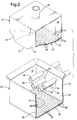
- Figure 2 illustrates a female mold member 22 and male mold member 24 in the mold-open position.
- the female mold member 22 comprises a plurality of walls 26, 28, 30 and 32 defining a mold cavity 34.
- a plurality of openings 36 are provided in the side wall 30 to receive a plurality of injectors 8A-8D from the filling machine, as will be described in more detail hereinafter.
- the bottom wall 32 of the mold 22 comprises a plurality of apertures 38 so as to render the bottom wall 32 permeable to gas.
- the centermost portion 40 of the wall 32 serves as a stripper plate for ejecting the cushion from the cavity 34 at the end of the processing cycle as will be described in more detail hereinafter.
- the male mold member 24 comprises a lower wall 42 for shaping the upper surface of the cushion and has a plurality of apertures 44 therein for rendering the wall 42 gas permeable.
- the gas-permeable wall 42 is backed up by a plenum 46 which, in turn, is connected to a conduit 48 for exhausting (or providing as appropriate) heating and cooling gases from the plenum 46.
- the permeable wall 42 of the male mold member 24 is contoured to shape the outer surface of the cushion, and includes a first central portion 41 defining a first zone in the mold cavity which shapes the central region of the cushion, and a pair of contoured lateral portions 43 and 45 which rise above the central portion 41 for shaping bolsters along the sides of the cushion.
- the contoured portions 43 and 45 define second zones of the mold cavity where higher density loadings of fibers are to be deposited to provide lateral bolsters which are integral with, but higher density than, the central region of the cushion.
- the central zone of the mold cavity defined by the wall portion 41 is fed fibers under relatively low air pressure/volume from the inboard injectors 8B and 8C while the lateral or second zone portions of the mold cavity are fed fibers under relatively high air pressure/volume from the outermost injectors 8A and 8D.
- Figures 3-5 depict apparatus for making cushions according to the process described above with different components of the apparatus in different positions at various times in the cycle.
- Figure 3 shows the apparatus essentially at the beginning of the process with the male mold member 24 in a semi-closed position at the mouth of the cavity 34 in the female mold member 22.
- the injectors 8C and 8D extend through the openings 36 to almost the other side of the mold cavity 34 which is itself, along with the wall 42, coated with a Teflon layer 35.
- Each injector 8A-D fits in telescoping fashion over a three inch diameter stationary feed tube 50 and 51 extending from the filling machine 52, and is caused to move fore and aft by a drive mechanism 53 which is preferably a ball and screw type linear actuator 54 powered by reversible motor 56.
- Alternative drive mechanisms include pneumatic/hydraulic cylinders, rack and pinion gears, or the like (not shown).
- the injectors 8 move slowly from the fully extended position shown in Figure 3 to the retracted position shown in Figure 4 as they dispense the fibers 10 into the mold cavity 34 so as to provide a substantially even distribution of the fibers in the cavity 34.
- the plenum 46 in the upper mold member 24 is pressurized with air so as to provide a current of downwardly moving air which serves to help distribute the fibers evenly while packing them in the bottom of the mold cavity 34.
- the filling tubes (e.g., 50 and 51) are connected to a filling machine 52 which is essentially a commercially available machine marketed for filling pillows with fibers and sold by the Ormont Corporation as their Model No. TRP11 Commander filling machine. That machine essentially includes a motor 58 for driving a plurality of impellers or blades (not shown) inside the machine for keeping the fibers stirred up and airborne in the machine 52.
- a conduit 60 delivers the fibers to the machine 52 from a remote source thereof (not shown).
- the end of each filling tube 50 and 51 inside the filling machine 52 is open at the top 62 for admitting the airborne fibers to the tubes 50 and 51.
- Nozzles 64 and 66 emit a jet of air into their associated filling tubes 50 and 51, respectively, which draw fibers into the tubes 50 and 51 through the openings 62 and convey them down the tubes 50 and 51 through the injectors 8C and 8D into the mold cavity 34.
- the air pressure and volume provided by nozzle 66 to the tube 51 and injector 8C is higher than the air pressure and volume provided by nozzle 64 to tube 50.
- injector 8A will have a higher air pressure/volume than injector 8B for packing more fibers into the bolster-forming zone of the cavity defined by the contoured lateral portion 43 of wall 42.
- the bottom wall 32 of the mold 22 includes a plurality of apertures 38 so as to render the bottom wall permeable to gases.
- the bottom wall 42 of the male mold member 24 contains a plurality of perforations 44 for the same reason.
- the bottom of the female mold 22, and hence the gas-permeable wall 32 is encompassed by a plenum 68 which is connected to a conduit 70 for supplying or removing the gases from the plenum 68 as needed.
- a heater 72 is coupled to the conduit 70 and to a blower 74 for heating air passing through the conduit 70 when the blower 74 is energized to pressurize the plenum 68.
- a stripper plate 40 forms part of the perforated wall 32 and is connected to an elevator 76 by means of rods 78 for ejecting the cushion from the mold cavity 34 upon completion of the heating/cooling cycle.
- Temperature sensors 80 and 82 e.g., thermocouples
- Figure 4 is like Figure 3 except that it shows the injectors 8D and 8C in the fully retracted positions along the tubes 50 and 51, and the male mold member 24 fully seated in the female mold 22 compressing the fiber mixture 10 to the desired shape. This position is retained during the heating and cooling cycle which begins by the blower 74 pumping gas (i.e., air) through the heater 72 into the conduit 70 and plenum 68, through the gas-permeable wall 32 and the fiber bed 10, and finally exhausting the gas from the bed 10 out the pipe/duct 48 via the gas-permeable wall 42 and plenum 46.
- gas i.e., air
- Hot air flow continues until the temperature sensed at the sensor 82 approaches that sensed at the sensor 80 which is indicative of the fact that the fibers 10 are substantially uniformly heated throughout and can absorb substantially no additional heat.
- the heater 72 is shut off, and ambient or cool air pumped into the plenum 68 and through the fiber mixture to cool and bond the low melting point fibers to the high melting point fibers at the intersections thereof. Cooling continues until the temperature at sensor 82 drops to approximately the temperature sensed at sensor 80 which is indicative that the fibers 10 have cooled sufficiently as not to give off any additional heat, and accordingly have bonded the low melting point fibers to the high melting point fibers sufficient for the cushion to retain the shape provided during the compression step.
Landscapes
- Engineering & Computer Science (AREA)
- Mechanical Engineering (AREA)
- Chemical & Material Sciences (AREA)
- Composite Materials (AREA)
- Nonwoven Fabrics (AREA)
- Treatment Of Fiber Materials (AREA)
Applications Claiming Priority (2)
| Application Number | Priority Date | Filing Date | Title |
|---|---|---|---|
| US573771 | 1995-12-18 | ||
| US08/573,771 US5571465A (en) | 1995-12-18 | 1995-12-18 | Method for making fiber-filled bolstered cushion |
Publications (2)
| Publication Number | Publication Date |
|---|---|
| EP0780503A2 true EP0780503A2 (de) | 1997-06-25 |
| EP0780503A3 EP0780503A3 (de) | 1999-02-03 |
Family
ID=24293336
Family Applications (1)
| Application Number | Title | Priority Date | Filing Date |
|---|---|---|---|
| EP96203164A Withdrawn EP0780503A3 (de) | 1995-12-18 | 1996-11-13 | Verfahren und Vorrichtung zur Herstellung eines fasergefüllten, gepolsterten Kissens |
Country Status (2)
| Country | Link |
|---|---|
| US (1) | US5571465A (de) |
| EP (1) | EP0780503A3 (de) |
Families Citing this family (14)
| Publication number | Priority date | Publication date | Assignee | Title |
|---|---|---|---|---|
| US5679296A (en) * | 1995-09-29 | 1997-10-21 | Davidson Textron, Inc. | Cushioned automotive interior trim part and process or making same |
| WO1998024958A1 (fr) * | 1996-12-05 | 1998-06-11 | Teijin Limited | Procede de moulage d'agregats de fibres |
| JP3697474B2 (ja) * | 1997-07-30 | 2005-09-21 | 帝人ファイバー株式会社 | 繊維集合体の型詰め方法 |
| US6235391B1 (en) | 1998-02-03 | 2001-05-22 | Foamex L.P. | Filling material for cushions |
| US6063317A (en) * | 1998-04-01 | 2000-05-16 | Oakwood Padded Products, Inc. | Method for molding polymeric fibers into products |
| US6588462B1 (en) * | 2000-05-26 | 2003-07-08 | Taro Ogawa | Filling device and filling method |
| AU2001278446A1 (en) * | 2000-06-15 | 2001-12-24 | Merck Patent G.M.B.H | A method for producing sphere-based crystals |
| DE10324735B3 (de) * | 2003-05-30 | 2004-11-11 | Fiber Engineering Gmbh | Verfahren und Vorrichtung zur Herstellung von dreidimensional ausgeprägten Formteilen sowie Formteil |
| US7490392B2 (en) * | 2005-12-07 | 2009-02-17 | Steelcase Inc. | Seating unit with formed cushion, and manufacturing method |
| US7514026B1 (en) * | 2007-11-30 | 2009-04-07 | Dzs, Llc. | Method for recycling floor coverings |
| IT1393398B1 (it) * | 2009-03-19 | 2012-04-20 | Cgm Spa | Metodo per realizzare prodotti di plastica |
| WO2016112989A1 (en) * | 2015-01-16 | 2016-07-21 | Schukra Gerätebau Gmbh | Method, tool and system for producing a product from fiber material |
| US11324337B2 (en) * | 2016-08-17 | 2022-05-10 | Worldwise, Inc. | Bed filling system |
| DE102023107442A1 (de) * | 2023-03-24 | 2024-09-26 | Bayerische Motoren Werke Aktiengesellschaft | Werkzeug zur Herstellung eines Polsters im Thermoformprozess |
Family Cites Families (16)
| Publication number | Priority date | Publication date | Assignee | Title |
|---|---|---|---|---|
| US3739397A (en) * | 1972-01-06 | 1973-06-19 | Protective Prod Inc | Shoulder pad apparatus |
| DE2331304A1 (de) * | 1973-06-20 | 1975-01-23 | Basf Ag | Verfahren zur herstellung von schaumstoff-formkoerpern aus olefinpolymerisaten |
| US4608213A (en) * | 1983-11-04 | 1986-08-26 | Ikeda Bussan Co., Ltd. | Method and mold apparatus for molding a padding member |
| US4568581A (en) * | 1984-09-12 | 1986-02-04 | Collins & Aikman Corporation | Molded three dimensional fibrous surfaced article and method of producing same |
| US4812283A (en) * | 1986-05-02 | 1989-03-14 | Allied-Signal Inc. | Method of manufacture of formed article |
| US5111579A (en) * | 1989-12-14 | 1992-05-12 | Steelcase Inc. | Method for making a frameless acoustic cover panel |
| US5229052A (en) * | 1990-02-23 | 1993-07-20 | Wellman Machinery Of Michigan, Inc. | Apparatus and method for applying multiple type fibers to a foraminous surface |
| FI86537C (fi) * | 1990-06-08 | 1992-09-10 | Juha Vesa | Anordning foer framstaellning av formkroppar. |
| JPH05220278A (ja) * | 1992-02-12 | 1993-08-31 | Nhk Spring Co Ltd | クッション体およびその製造方法 |
| JP2882179B2 (ja) * | 1992-04-24 | 1999-04-12 | トヨタ自動車株式会社 | クッション材の製造方法 |
| JPH05345358A (ja) * | 1992-06-15 | 1993-12-27 | Araco Corp | 繊維製クッション体の製造方法 |
| FI90651C (fi) * | 1993-01-13 | 1994-03-10 | Nowo Dev Oy | Menetelmä ja laite kaasua läpäisevän kappaleen valmistamiseksi kaasua läpäisevässä muotissa |
| US5482665A (en) * | 1994-03-18 | 1996-01-09 | General Motors Corporation | Method/apparatus for making fiber-filled cushion |
| US5492662A (en) * | 1994-10-17 | 1996-02-20 | Kargol; James A. | Process for forming multiple density body from fibrous polymeric material and vehicle seat component formed thereby |
| US5494627A (en) * | 1994-10-17 | 1996-02-27 | Kargol; James A. | Method for making a vehicle seat component with improved resistance to permanent deformation |
| JPH0985759A (ja) * | 1995-09-26 | 1997-03-31 | Teijin Ltd | 繊維集合体の成形方法 |
-
1995
- 1995-12-18 US US08/573,771 patent/US5571465A/en not_active Expired - Fee Related
-
1996
- 1996-11-13 EP EP96203164A patent/EP0780503A3/de not_active Withdrawn
Also Published As
| Publication number | Publication date |
|---|---|
| EP0780503A3 (de) | 1999-02-03 |
| US5571465A (en) | 1996-11-05 |
Similar Documents
| Publication | Publication Date | Title |
|---|---|---|
| US5482665A (en) | Method/apparatus for making fiber-filled cushion | |
| US5569425A (en) | Method and apparatus for making fiber-filled cushion | |
| US5571465A (en) | Method for making fiber-filled bolstered cushion | |
| JP2025515735A (ja) | クッションを製造するための方法及び装置 | |
| JP4785253B2 (ja) | メルトブローン成形された芯材を有する、メルトブローン成形されたフィルタカートリッジを形成するための方法および装置、ならびにそれによって形成されたフィルタカートリッジ | |
| US6033501A (en) | Process for preparing cushioning structure using fiber assembly and apparatus therefor | |
| EP0583542B1 (de) | Verfahren zur Herstellung von Schaumstoffkörpern mit Haut und Formvorrichtung hierfür | |
| CN119497685A (zh) | 网结构及制造方法 | |
| MXPA01008172A (es) | Maquina de moldeo automatico para producir productos de espuma plastica a partir de perlas. | |
| US12420497B2 (en) | Molding of fiber blanks into three-dimensional fiber block articles | |
| US11554538B1 (en) | Feed housing purge system | |
| CN1258598A (zh) | 模制纤维混合物的方法和装置 | |
| EP0770154B1 (de) | Verfahren zum formen von faseraggregaten | |
| US4044715A (en) | Apparatus for manufacturing cushion materials | |
| JP3827995B2 (ja) | 繊維成形体の製造方法及び製造装置 | |
| JPH06328550A (ja) | 複合成形体及びその製造方法 | |
| JP3733411B2 (ja) | クッション材の成形方法 | |
| JP7568322B1 (ja) | 不織布製造装置、及び不織布製造方法 | |
| CN107635826B (zh) | 控制模具中的纤维的系统和方法 | |
| WO2000066339A1 (en) | Method of producing resin molded article and device for producing resin molded article | |
| JP3704547B2 (ja) | 繊維集合体の成形方法 | |
| JP6412650B2 (ja) | 製品を繊維材料から製造する方法、ツールおよびシステム | |
| US4096014A (en) | Method of manufacturing cushion materials | |
| JP2001341150A (ja) | 発泡性熱可塑性樹脂粒子の型内充填方法及び装置 | |
| JP2003138458A (ja) | 不織布及びその製造方法 |
Legal Events
| Date | Code | Title | Description |
|---|---|---|---|
| PUAI | Public reference made under article 153(3) epc to a published international application that has entered the european phase |
Free format text: ORIGINAL CODE: 0009012 |
|
| AK | Designated contracting states |
Kind code of ref document: A2 Designated state(s): DE FR GB |
|
| RAP1 | Party data changed (applicant data changed or rights of an application transferred) |
Owner name: LEAR CORPORATION |
|
| PUAL | Search report despatched |
Free format text: ORIGINAL CODE: 0009013 |
|
| AK | Designated contracting states |
Kind code of ref document: A3 Designated state(s): DE FR GB |
|
| STAA | Information on the status of an ep patent application or granted ep patent |
Free format text: STATUS: THE APPLICATION IS DEEMED TO BE WITHDRAWN |
|
| 18D | Application deemed to be withdrawn |
Effective date: 19990804 |