EP0780576A2 - Strömungsmaschine in Spiralbauweise - Google Patents
Strömungsmaschine in Spiralbauweise Download PDFInfo
- Publication number
- EP0780576A2 EP0780576A2 EP96120525A EP96120525A EP0780576A2 EP 0780576 A2 EP0780576 A2 EP 0780576A2 EP 96120525 A EP96120525 A EP 96120525A EP 96120525 A EP96120525 A EP 96120525A EP 0780576 A2 EP0780576 A2 EP 0780576A2
- Authority
- EP
- European Patent Office
- Prior art keywords
- scroll
- revolving
- stationary
- laps
- housing
- Prior art date
- Legal status (The legal status is an assumption and is not a legal conclusion. Google has not performed a legal analysis and makes no representation as to the accuracy of the status listed.)
- Withdrawn
Links
Images


Classifications
-
- F—MECHANICAL ENGINEERING; LIGHTING; HEATING; WEAPONS; BLASTING
- F04—POSITIVE - DISPLACEMENT MACHINES FOR LIQUIDS; PUMPS FOR LIQUIDS OR ELASTIC FLUIDS
- F04C—ROTARY-PISTON, OR OSCILLATING-PISTON, POSITIVE-DISPLACEMENT MACHINES FOR LIQUIDS; ROTARY-PISTON, OR OSCILLATING-PISTON, POSITIVE-DISPLACEMENT PUMPS
- F04C27/00—Sealing arrangements in rotary-piston pumps specially adapted for elastic fluids
- F04C27/008—Sealing arrangements in rotary-piston pumps specially adapted for elastic fluids for other than working fluid, i.e. the sealing arrangements are not between working chambers of the machine
- F04C27/009—Shaft sealings specially adapted for pumps
-
- F—MECHANICAL ENGINEERING; LIGHTING; HEATING; WEAPONS; BLASTING
- F01—MACHINES OR ENGINES IN GENERAL; ENGINE PLANTS IN GENERAL; STEAM ENGINES
- F01C—ROTARY-PISTON OR OSCILLATING-PISTON MACHINES OR ENGINES
- F01C21/00—Component parts, details or accessories not provided for in groups F01C1/00 - F01C20/00
- F01C21/10—Outer members for co-operation with rotary pistons; Casings
- F01C21/102—Adjustment of the interstices between moving and fixed parts of the machine by means other than fluid pressure
-
- F—MECHANICAL ENGINEERING; LIGHTING; HEATING; WEAPONS; BLASTING
- F04—POSITIVE - DISPLACEMENT MACHINES FOR LIQUIDS; PUMPS FOR LIQUIDS OR ELASTIC FLUIDS
- F04C—ROTARY-PISTON, OR OSCILLATING-PISTON, POSITIVE-DISPLACEMENT MACHINES FOR LIQUIDS; ROTARY-PISTON, OR OSCILLATING-PISTON, POSITIVE-DISPLACEMENT PUMPS
- F04C18/00—Rotary-piston pumps specially adapted for elastic fluids
- F04C18/02—Rotary-piston pumps specially adapted for elastic fluids of arcuate-engagement type, i.e. with circular translatory movement of co-operating members, each member having the same number of teeth or tooth-equivalents
- F04C18/0207—Rotary-piston pumps specially adapted for elastic fluids of arcuate-engagement type, i.e. with circular translatory movement of co-operating members, each member having the same number of teeth or tooth-equivalents both members having co-operating elements in spiral form
- F04C18/0215—Rotary-piston pumps specially adapted for elastic fluids of arcuate-engagement type, i.e. with circular translatory movement of co-operating members, each member having the same number of teeth or tooth-equivalents both members having co-operating elements in spiral form where only one member is moving
- F04C18/0223—Rotary-piston pumps specially adapted for elastic fluids of arcuate-engagement type, i.e. with circular translatory movement of co-operating members, each member having the same number of teeth or tooth-equivalents both members having co-operating elements in spiral form where only one member is moving with symmetrical double wraps
-
- F—MECHANICAL ENGINEERING; LIGHTING; HEATING; WEAPONS; BLASTING
- F04—POSITIVE - DISPLACEMENT MACHINES FOR LIQUIDS; PUMPS FOR LIQUIDS OR ELASTIC FLUIDS
- F04C—ROTARY-PISTON, OR OSCILLATING-PISTON, POSITIVE-DISPLACEMENT MACHINES FOR LIQUIDS; ROTARY-PISTON, OR OSCILLATING-PISTON, POSITIVE-DISPLACEMENT PUMPS
- F04C18/00—Rotary-piston pumps specially adapted for elastic fluids
- F04C18/02—Rotary-piston pumps specially adapted for elastic fluids of arcuate-engagement type, i.e. with circular translatory movement of co-operating members, each member having the same number of teeth or tooth-equivalents
- F04C18/0207—Rotary-piston pumps specially adapted for elastic fluids of arcuate-engagement type, i.e. with circular translatory movement of co-operating members, each member having the same number of teeth or tooth-equivalents both members having co-operating elements in spiral form
- F04C18/0246—Details concerning the involute wraps or their base, e.g. geometry
- F04C18/0269—Details concerning the involute wraps
Definitions
- This invention relates to scroll fluid apparatuses, which comprise at least one stationary scroll and a revolving scroll for compressing gas and discharging the compressed gas to the outside, and also to a method of adjusting scroll position in the same.
- Stationary scrolls and revolving scrolls which have laps with the thickness thereof reducing from the stem on the scroll body mirror-finished surface toward the tip, are well known in the art as disclosed in Japanese Laid-Open Patent Publication No. 59-79090.
- the facing laps may strike each other while a revolving scroll is revolved, thus generating noise, increasing the load, requiring increased drive power and reducing the durability.
- scroll vacuum pumps are well known in the art, in which gas sucked from a vessel to be evacuated is taken in from the outer side of laps of stationary and revolving scrolls, and compressed in a progressively reducing the volume of sealed space formed by the laps one another, the compressed gas being discharged from a discharge port provided in a central part of the pump.
- a stationary scroll 50A comprises a scroll body 50Aa with a stationary lap 50Ab provided on the inner side.
- a tip seal 54 which is fitted in the lap 50Ab is held in frictional contact with an inner mirror-finished surface of an opposed scroll body.
- the stationary scroll 50A has a suction hole 50Ac, which is provided on the outer side of the lap 50Ab and communicated with a vessel (not shown) to be evacuated, and also has a discharge hole 50Ad provided in the center of the scroll body 50Aa for discharging compressed gas.
- a revolving scroll 51A comprises a scroll body 51Aa having a revolving lap 51Ab with a tip seal 54 fitted at the tip of lap 51Ab provided on the inner side and held in frictional contact with the opposed scroll body mirror-finished surface, and a revolving lap 51Ae with a revolving seal 53 fitted at the tip of 51Ae provided at the outside of revolving lap 51Ab and held in frictional contact with the scroll body 50Aa mirror-finished surface.
- the scroll body 51Aa has a central integral shaft 51Ac, which is eccentrically coupled to a shaft 51Ad coupled to a motor (not shown).
- the lap 51Ab is in mesh with the lap 50Ab of the stationary scroll 50A, and the revolving scroll 51A can be revolved relative to the stationary scroll 50A, whereby gas sucked through the suction hole 50Ac is progressively compressed in a sealed space formed by the laps 50Ab and 51Ab and discharged through the discharge hole 50Ad.
- a stationary scroll 50B comprises a scroll body 50Ba with a lap 50Bb provided on the inner side, a tip seal 54 being fitted in the lap 50Bb and held in frictional contact with an opposed scroll body mirror-finished surface.
- the stationary scroll 50B has a suction hole 50Bc, which is provided on the outer periphery of the scroll body 50Ba and communicated with a vessel (not shown) to be evacuated, and also has a discharge hole 50Bd provided in the center of the scroll body 50Ba for discharging compressed gas.
- a revolving scroll 51B comprises a scroll body 51Ba with a lap 51Bb provided on the inner side, a tip seal 54 being fitted in the tip of lap 51Bb and held in frictional contact with the opposed scroll body mirror-finished surface.
- the scroll body 51Ba has a central integral shaft 51Bc which is eccentrically coupled to a shaft 51Bd coupled to a motor (not shown).
- the lap 51Bb is in mesh with the lap 50Bb of the stationary scroll 50B, and the revolving scroll 51B can be revolved relative to the stationary scroll 50B.
- a housing 52 which is coupled to the scroll body 50Ba of the stationary scroll 50B, provides an inner space 56 accommodating the revolving scroll 51B.
- the housing 52 has a central opening 52a, through which a drive shaft 51Bd of the revolving scroll 51B rotatably penetrates via a rotational seal 57. Gas sucked through the suction hole 50Bc is progressively compressed in a sealed space formed by the laps 50Bb and 51Bb and discharged through the discharge hole 50Bd.
- the scroll compressor sucks substantially the same pressure during its operation, leading to no substantial pressure difference between the pressures on the outer and inner sides of the revolving seal 53 or rotating seal 57, i.e., to no substantial gas leakage problem.
- the pressure of the gap taken in through the suction hole 50Ac (in the case of Fig. 5(a)) or 50Bc (in the case of Fig. 5(b)) which is communicated to the vessel to be evacuated is progressively reduced with the progress of the evacuation, thus producing a progressively increasing difference between the pressures of atmospheric air 58 and the taker-in gas in the peripheral inner space 56 or 59 of the scroll lap on the outer and inner sides of the revolving seal 53 or rotating seal 57, the pressure difference becoming maximum at the end of the evacuation of the vessel.
- the revolving seal 53 is revolved with the revolving of the revolving scroll 51A, while the rotating seal 57 is rotated with the rotation of the shaft 51Bd of the revolving scroll 51B.
- the seal 53 or 57 is worn out, the sealing pressures between it and the associated scroll body mirrors-finished surface, and also between it and the associated revolving scroll shaft outer periphery are reduced. In consequence, the seal is pushed inward by the atmospheric air pressure, resulting the formation of a clearance, through which atmospheric air is forced into the scroll mechanism to reduce the pumping efficiency of the vacuum pump.
- Another object of the invention is to provide a scroll fluid apparatus, which is free from any increase of the difference between gas pressures on the inner and outer sides of the scroll mechanism, i.e., on the inner and outer sides of dynamic seals of a rotating drive part.
- a further object of the invention is to provide a scroll fluid apparatus, which is reduced in size and improved in durability.
- a scroll fluid apparatus which comprises a stationary scroll and a revolving scroll, these scrolls having laps reducing in thickness from the stem on the scroll body mirror-finished surface toward the tip thereof, fluid taken in through a suction port provided on the outer side of the apparatus being compressed while being forced removing gradually through a sealed space formed in order by the laps in mesh with each other toward a discharge port provided in the neighborhood of the center of the apparatus and then discharged through the discharge port.
- elastic tip seals are fitted in tip seal grooves formed in the tip of the laps such as to form the sealed space together with laps in frictional contact with opposed mirror-finished surface of scroll body each other, and a housing defining an inner space is coupled via a spacer to the stationary scroll, in which the revolving scroll is disposed such as to be pushed by the inner surface of the housing toward the stationary scroll body mirror-finished surface, gap between the facing laps being adjustable by appropriately selecting the spacer.
- the revolving scroll 3 permits the revolving scroll 3 to be pushed by the inner surface 4b of a housing part 4 to cause the tip seal 14, which is fitted in the tip seal groove 26e (Fig. 2) provided in the revolving scroll lap tip, to be elastically deformed and held in gas-tight frictional contact with the opposed mirror-finished surface.
- the position of the inclined surface 26a of the lap 26 of the revolving scroll 3, as shown by the solid line, can be adjusted to the position as shown by the dashed line 26a'. That is, the distance L1 between the laps 26 and 6 with the inclined surface 26a at the position R1, can be reduced to the distance L2 by the position adjustment to the position R2 shown on the dashed line 26a'. In this way, the gap between the facing laps can be adjusted by appropriately selecting the spacer 10.
- the revolving scroll, the stationary scroll and the housing may be prepared in different sizes in predetermined ranges, and their sizes may be selected to be in pertinent ranges to be mounted respectively.
- a scroll vacuum pump comprising at least one stationary scroll and a revolving scroll, wherein the stationary scroll has a scroll body with a central bore, the revolving scroll having a scroll body with a shaft, which is fitted for rotation in the central bore of the stationary scroll via a dynamic seal.
- the stationary scroll is constituted by a housing having the central bore, in which the shaft of the revolving scroll is fitted, a stationary scroll lap extending spirally with above central bore as the center from the vicinity of the central bore toward the outer periphery and being in mesh with a revolving scroll lap, a suction port provided on the outer side of the stationary scroll lap for sucking gas, and a discharge port provided near the central bore for discharging the gas taken in from the outer side of the stationary scroll lap after the gas has been compressed, the revolving scroll being disposed in an inner space defined by the housing and revolved relative to the stationary scroll, the shaft of the revolving scroll being fitted for rotation in the central bore of the stationary scroll via a dynamic seal.
- a scroll vacuum pump which comprises a double lap revolving scroll having a scroll body with laps each on each side, and a stationary scroll having a first housing part with a stationary lap in frictional contact with one of the laps of the revolving scroll and a second housing part with a stationary lap in frictional contact with the other lap of the revolving scroll, the first and second housing parts each constituting a stationary scroll body with a central bore, in which a shaft of the revolving scroll is fitted for rotating in the both central bores via a dynamic seal, the first and second housing parts being coupled to each other via a static seal in the vacuum scroll pump outer periphery other than a region thereof to be in frictional contact with the outer periphery of the revolving scroll.
- housing parts 4 and 5 form stationary scrolls with scroll bodies 4g and 5g.
- the scroll body 4g has a bore 4i and a greater diameter bore 4h
- the scroll body 5g has a bore 5h and a greater diameter bore 5i.
- the revolving scroll has a shaft 11, which is fitted for rotation in the greater diameter bores 4h and 5i via dynamic seals 16.
- the gas that is discharged through a discharge port 5c after being compressed in the scroll mechanism is under a higher pressure than the atmospheric air pressure.
- This means that the pressure in a central part of the inner space 21A, 21B, 22A and 22B in the scroll mechanism is far higher than in a peripheral part of the inner space, specifically close to the atmospheric air pressure, during the operation of the mechanism.
- the dynamic seals 16 are located at positions near the discharge port, at which positions the pressure of the inner compressed gas does not substantially differ from the atmospheric air pressure before the compressed gas is discharged to the outside. These seals thus can prevent the efficiency of the scroll mechanism from being reduced by externally introduced gas as a result of their wear, thus improving the durability of the scroll mechanism.
- said housing is constituted by a plurality of separate housing parts as noted above, two of which are coupled to each other via a static seal provided in the outer periphery of the scroll mechanism other than a region in frictional contact with the outer periphery of said revolving scroll.
- the adjacent housing parts i.e., the housing parts 4 and 5 (Fig. 1), are assembled together by inserting the shaft 11 into the central bore of one of them, i.e., the housing part 4, then disposing the revolving scroll therein by fitting a central bore of the revolving scroll on a portion 11a of the shaft 11, then engaging the other housing part 5 with the housing part 4, and then securing the two housings 4 and 5 to each other with bolts and nuts (not shown).
- the housing which comprises these separate parts can be assembled orderly and, if necessary, it is possible to adjust the housing inner space dimension in the axial direction of the shaft by appropriately selecting the spacer between the adjacent housing parts.
- the assembling of the scroll vacuum pump may be facilitated by preliminarily measuring dimensions of the housing parts and the revolving scroll and grouping these components of eventual products in suitable dimension ranges together with pertinent spacer dimension ranges.
- the static seal 15 is held stationary without possibility of producing any clearance while the gas sucked through a suction port 8 is reduced in pressure with the progress of the evacuation of the vessel.
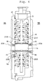
- Fig. 1 is a schematic view showing an embodiment of the scroll fluid apparatus according to the invention.
- Fig. 2(a) is an enlarged-scale view showing a part A shown in Fig. 1.
- Fig. 2(b) is a view for describing a function when adjusting an inter-lap gap.
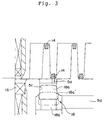
- Fig. 3 is an enlarged scale view showing a part B shown in Fig. 1.
- the scroll vacuum pump designated at 1 has a shaft 11, which has its right end coupled to a drive shaft of a motor (not shown) and able to be driven by the torque thereof.
- the shaft 11 has a central eccentric portion 11a with an increased outer diameter, which has its ends supported for rotation in bearings and dynamic seals 16 provided in housing parts 4 and 5.
- the dynamic seals 16 serve to prevent intrusion of external particles and also prevent gas leaks to and from the outside of the scroll vacuum pump. They are desirably excellent in wear resistance. As for the sealing property, however, they need provide only the usual mechanical seal since they are located at positions subject to less pressure difference between the inside and outside of the scroll mechanism.
- the housing parts 4 and 5 form stationary scrolls. They are cup-like in shape, and their outer peripheral walls which function as casings are sealed to each other via a spacer 10 and an O-ring 15 as a static seal, thus forming an inner sealed space.
- the housing part 4 has a lap sliding surface (i.e., a mirror-finished surface) 4b perpendicular to its axis. Its central portion has a bore 4i, which is open to the lap sliding surface 4b and in which a non-eccentric portion of the shaft 11 other than the eccentric portion 11a thereof is fitted for rotation, and an increased diameter bore 4h, in which the dynamic seal 16 noted above is fitted.
- the lap sliding surface 4b has a lap 7 extending spirally outward from the neighborhood of the bores.
- a tip seal 14 is fitted in a tip seal groove formed in the top of the lap 7.
- the tip seal 14 is made of a fluorine type resin or like self-lubricating material and in contact with the opposed lap sliding surface to provide a perfectly seal.
- the peripheral wall of the housing part 4 has three elements of a revolving mechanism 17, radially spaced apart at an interval of 120 degrees.
- the revolving mechanism 17 is coupled to a revolving scroll to be described later.
- the housing part 4 has a suction port 8, which is formed in the outer periphery and communicated with a vessel (not shown) to be evacuated for sucking gas therefrom through it.
- the housing part 5 has a lap sliding surface 5b perpendicular to its axis. It's central portion has a bore 5h, which is open to the lap sliding surface 5b and in which a non-eccentric portion of the shaft 11 other than the eccentric portion 11a thereof is fitted for rotation, and an increased diameter bore 5i, in which the dynamic seal 16 is fitted.
- the lap sliding surface 5b has a lap 6 extending spirally outward from the neighborhood of the bores.
- a tip seal 14 is fitted in a tip seal groove formed in the tip of the lap 6 and in contact with the opposed lap sliding surface to provide a perfect seal.
- a revolving scroll 3 is disposed for revolving in the inner space formed by the housing parts 4 and 5.
- the revolving scroll 3 has a disc-like scroll body having opposite side lap sliding surfaces 3d and 3e with laps 26 and 27 thereon, which are able to engage with the stationary scroll laps.
- the revolving scroll 3 has a central bore 3a which is fitted on the eccentric portion 11a of the shaft 11.
- the bore 3a is surrounded over the entire length of the eccentric portion of the shaft 11 by laps 26a and 27a.
- the housing part 5 has a discharge port 5c, which is open to the lap sliding surface 5b at a position thereof near the end of the lap 6.
- a check valve 18 is provided in the discharge port 5c.
- the check valve 18 has a head 18a to be forced into sealing contact with the wall surface of the discharge port 5c, and a stem 18b for pushing the head 18a with a predetermined pressure.
- valve head 18a When the pressure of the gas having been compressed in the sealed space formed by the stationary and revolving scroll laps 6 and 26 exceeds the gas pressure in a discharge passage 9d, the valve head 18a is pushed open as shown by the phantom line 18a' to produce a clearance, allowing the compressed gas to be discharged through a discharge opening 5d, the discharge port 5c and the discharge passage 9d, and thence through a discharge opening 9a provided in the outer peripheral wall of the housing part 4 to the outside.
- the lap sliding surface 4b has a discharge port, a check valve, a discharge passage, etc. like the discharge port 5c, the check valve 18, the discharge passage 9d, etc. being disposed on the lap sliding surface 5b (not shown), respectively.
- Cooling fans 12 and 13 for cooling the scroll vacuum pump are mounted on end portions of the shaft 11 outside the housing parts 5 and 4.
- this embodiment related to the scroll type vacuum pump which comprises at least one stationary scroll and a revolving scroll, the revolving scroll having a shaft fitted for rotation in a central bore formed in the scroll body of each stationary scroll via a dynamic seal.
- either stationary scroll as a housing having the central bore penetrated by the shaft supporting the revolving scroll thereon has a lap extending spirally outward from the neighborhood of the central bore toward the outer periphery and in mesh with a revolving scroll lap
- either stationary scroll lap has a suction port provided on the outer side of its lap for sucking gas
- either stationary scroll has a discharge port provided near the central bore for discharging gas that has been compressed after being taken in from the outer side of the scroll mechanism
- the revolving scroll being disposed in a housing inner space for revolution relative to each stationary scroll, the shaft supporting the revolving scroll being fitted for rotation in the central bore of each stationary scroll via a dynamic seal.
- the rotation of the shaft 11 causes wear of the dynamic seals 16 intervening between the housing parts 4 and 5 and the shaft 11, and eventually produces clearances between the shaft 11 and the dynamic seals 16. Since the pressure of the atmospheric air 58 is higher than the pressure inside the scroll mechanism, it causes gas to enter through the clearances between the seals 16 and the drive shaft 11, the clearances between the stationary scroll laps and the revolving scroll laps and the clearances between the tip seals and the opposed sliding surfaces as shown by arrows 20A and 20B in Fig. 4.
- the gas that is discharged through the discharge port 5c after being compressed in the scroll mechanism is under a high pressure than the atmospheric air pressure. This means that the pressure in a central part of the inner space 21A, 21B, 22A and 22B in the scroll mechanism is far higher than in a peripheral part of the inner space, specifically close to the atmospheric air pressure, during the operation of the mechanism.
- the dynamic seals are located at positions near the discharge ports, at which positions the pressure of the inner compressed gas does not substantially differ from the atmospheric air pressure. These seals thus can prevent the efficiency of the scroll mechanism from being reduced by externally introduced gas as a result of their wear, thus improving the durability of the scroll mechanism.
- a plurality of housing parts are used with adjacent ones thereof coupled to each other via a static seal provided in the outer periphery of the assembled housing other than a region thereof in frictional contact with the outer periphery of the revolving scroll.
- the adjacent housing parts i.e., the housing parts 4 and 5 (Fig. 1), can be readily assembled together by inserting the shaft 11 into the central bore of one of them, i.e., the housing part 4, then disposing the revolving scroll therein by fitting the central bore of the revolving scroll on the portion 11a of the shaft 11, then engaging the other housing part 5 with the housing part 4, and then securing the two housings 4 and 5 to each other with bolts and nuts (not shown).
- the revolving scroll can be readily positioned because the shaft supporting it is supported by the two housing parts 4 and 5, and thus it can be driven accurately.
- the gap between the facing laps of the stationary and revolving scrolls i.e., the distance between the mirror-finished surfaces 5b and 4b, can be adjusted by appropriately selecting the thickness of the spacer 10 as shown Fig. 1.
- the tip seals 14 fitted in the tip seal grooves formed in the tip of its Laps 27 and 26 are elastically deformed to be in gas-tight frictional contact with the opposed mirror-finished surfaces 5b and 4b, while permitting the distance between the lap sliding surfaces (i.e., mirror-finished surfaces) 4b and 5b of the housing parts 4 and 5 to be varied.
- the distance between the mirror-finished surface 3e of the revolving scroll 3 and the mirror-finished surface 4b of the housing part 4 thus can be varied according to the thickness of the spacer 10.
- the lap 26 of the revolving scroll 3 is formed such that its inclined surface 26a extending from its stem 26c to its tip 26d has an equal inclination angle to the inclination angle of the inclined surface 6b of the lap 6.
- the capability of varying the distance between the mirror-finished surfaces of the housing parts 4 and 5 means that the position of the inclination surface 26a of the lap 26 of the revolving scroll 3 as shown by the solid line can be adjusted to, for instance, the position as shown by the dashed line 26a' by selecting the spacer.
- the gap L1 between the laps 26 and 6 with the inclined surface 26a at position R1 is reduced to a gap L2 with the inclined surface at position R2 as shown by the dashed line 26a'. In this way, it is possible to adjust the gap between the laps facing each other by appropriately selecting the spacer.
- a stationary scroll and a revolving scroll are prepared, which have laps reducing in thickness from the mirror-finished surface toward the tip, i.e., T1 > T2 and S1 > S2, an elastic tip seal being fitted in the tip of each lap and in frictional contact with the opposed mirror-finished surface, and a housing having an inner space for accommodating the revolving scroll therein, are prepared, the revolving scroll lap is meshed with the stationary scroll lap in a state that it is deviated by a predetermined angle, the revolving scroll in this state is disposed in the housing inner surface such that it is pushed by the housing inner surface toward the mirror-surface of the stationary scroll, and then the housing is mounted on the stationary scroll via a spacer.
- each tip seal fitted in the tip seal groove provided in each lap tip is elastically compressed to be in gas-tight frictional contact with the opposed mirror-finished surface. It is thus possible to adjust the scroll position through adjustment of the gap between the laps facing each other, which is made by appropriately selecting the spacer thickness.
- the dimensions of the components are not fixed but fluctuate within tolerances of each kind of component due to wear of cutting tools used in the process of manufacture and fluctuations of initial settings for each lot.
- the housing consists of a plurality of separate parts as noted above, with adjacent ones thereof coupled to each other via a static seal provided in outer periphery of the scroll vacuum pump other than a region thereof in frictional contact the revolving scroll outer periphery.
- the adjacent housing parts i.e., the housing parts 4 and 5 (Fig. 1) are assembled together by inserting the shaft 11 into the central bore of one of them, i.e., the housing part 4, then disposing the revolving scroll therein by fitting a central bore of the revolving shaft on a portion 11a of the shaft 11, then engaging the other housing part 5, and then securing the two housing parts 4 and 5 to each other with bolts and nuts (not shown).
- the components may be grouped into groups of those with negative errors, those with small errors and those with positive errors, etc. by measuring errors of components after the manufacture. Doing so permits assembling of the scroll mechanism by using components with similar errors.
- the separate housing parts thus permit orderly assembling.
- the assembling thus may be facilitated by preliminarily measuring the dimensions of the housing parts and the revolving scroll and grouping these components together with the spacer.
- the static seal 15 is held stationary without possibility of producing any clearance while the gas sucked through a suction port 8 is reduced in pressure with the progress of the evacuation of the vessel.
- the shaft supporting the revolving scroll is fitted for rotation in the stationary scroll body central bores via the dynamic seals, which are located in the neighborhood of the discharge port for discharging compressed gas.
- the pressure difference between the scroll mechanism inner and outer gases on the inner and outer sides of the dynamic seals, which seal the shaft for driving the revolving scroll are not big, and atmospheric air enters only very slightly, if any, due to wear of the dynamic seals. It is thus possible to prevent reduction of the efficiency of the scroll mechanism and improve the durability thereof.
- a stationary scroll and a revolving scroll with the laps thereof reducing in thickness from the scroll body mirror-finished surface toward the tip, elastic tips being fitted in the lap tips and in frictional contact with the opposed scroll body mirror-finished surfaces, and a housing having an inner space for accommodating the revolving scroll therein, are used, the revolving scroll being disposed in the housing inner space such as to be pushed by the housing inner surface toward the stationary scroll body mirror-finished surface, the housing being mounted on the stationary scroll via a spacer. It is thus possible to provide a scroll fluid apparatus, which permits setting an adequate gap between the laps facing each other according to the thickness of the spacer, as well as a method of scroll position adjustment in the same scroll fluid apparatus.
Landscapes
- Engineering & Computer Science (AREA)
- Mechanical Engineering (AREA)
- General Engineering & Computer Science (AREA)
- Physics & Mathematics (AREA)
- Fluid Mechanics (AREA)
- Rotary Pumps (AREA)
- Applications Or Details Of Rotary Compressors (AREA)
Applications Claiming Priority (2)
| Application Number | Priority Date | Filing Date | Title |
|---|---|---|---|
| JP34977395A JPH09177684A (ja) | 1995-12-21 | 1995-12-21 | スクロール型真空ポンプ |
| JP349773/95 | 1995-12-21 |
Publications (2)
| Publication Number | Publication Date |
|---|---|
| EP0780576A2 true EP0780576A2 (de) | 1997-06-25 |
| EP0780576A3 EP0780576A3 (de) | 1998-12-16 |
Family
ID=18406021
Family Applications (1)
| Application Number | Title | Priority Date | Filing Date |
|---|---|---|---|
| EP96120525A Withdrawn EP0780576A3 (de) | 1995-12-21 | 1996-12-19 | Strömungsmaschine in Spiralbauweise |
Country Status (2)
| Country | Link |
|---|---|
| EP (1) | EP0780576A3 (de) |
| JP (1) | JPH09177684A (de) |
Cited By (15)
| Publication number | Priority date | Publication date | Assignee | Title |
|---|---|---|---|---|
| WO1999014502A1 (fr) * | 1997-09-16 | 1999-03-25 | Ateliers Busch S.A. | Pompe a vide a spirales |
| WO2010070308A2 (en) | 2008-12-19 | 2010-06-24 | Edwards Limited | Scroll compressor |
| US20180163726A1 (en) * | 2016-12-06 | 2018-06-14 | Bryce R. Shaffer | Scroll type device having liquid cooling through idler shafts |
| US10508543B2 (en) | 2015-05-07 | 2019-12-17 | Air Squared, Inc. | Scroll device having a pressure plate |
| US10519815B2 (en) | 2011-08-09 | 2019-12-31 | Air Squared, Inc. | Compact energy cycle construction utilizing some combination of a scroll type expander, pump, and compressor for operating according to a rankine, an organic rankine, heat pump or combined organic rankine and heat pump cycle |
| US10683865B2 (en) | 2006-02-14 | 2020-06-16 | Air Squared, Inc. | Scroll type device incorporating spinning or co-rotating scrolls |
| US11047389B2 (en) | 2010-04-16 | 2021-06-29 | Air Squared, Inc. | Multi-stage scroll vacuum pumps and related scroll devices |
| US11067080B2 (en) | 2018-07-17 | 2021-07-20 | Air Squared, Inc. | Low cost scroll compressor or vacuum pump |
| US11454241B2 (en) | 2018-05-04 | 2022-09-27 | Air Squared, Inc. | Liquid cooling of fixed and orbiting scroll compressor, expander or vacuum pump |
| US11473572B2 (en) | 2019-06-25 | 2022-10-18 | Air Squared, Inc. | Aftercooler for cooling compressed working fluid |
| US11530703B2 (en) | 2018-07-18 | 2022-12-20 | Air Squared, Inc. | Orbiting scroll device lubrication |
| CN116928097A (zh) * | 2023-08-17 | 2023-10-24 | 合肥波林新材料股份有限公司 | 一种涡旋压缩机 |
| US11885328B2 (en) | 2021-07-19 | 2024-01-30 | Air Squared, Inc. | Scroll device with an integrated cooling loop |
| US11898557B2 (en) | 2020-11-30 | 2024-02-13 | Air Squared, Inc. | Liquid cooling of a scroll type compressor with liquid supply through the crankshaft |
| US11933299B2 (en) | 2018-07-17 | 2024-03-19 | Air Squared, Inc. | Dual drive co-rotating spinning scroll compressor or expander |
Citations (1)
| Publication number | Priority date | Publication date | Assignee | Title |
|---|---|---|---|---|
| JPS5979090A (ja) | 1982-10-27 | 1984-05-08 | Mitsubishi Electric Corp | スクロ−ル圧縮機 |
Family Cites Families (7)
| Publication number | Priority date | Publication date | Assignee | Title |
|---|---|---|---|---|
| JPS5776202A (en) * | 1980-10-30 | 1982-05-13 | Ebara Corp | Scroll type machine |
| GB2132276B (en) * | 1982-12-23 | 1986-10-01 | Copeland Corp | Scroll-type rotary fluid-machine |
| JPH0237192A (ja) * | 1988-05-12 | 1990-02-07 | Sanden Corp | スクロール型流体装置 |
| JP2712777B2 (ja) * | 1990-07-13 | 1998-02-16 | 三菱電機株式会社 | スクロール圧縮機 |
| JP3114232B2 (ja) * | 1991-05-20 | 2000-12-04 | 松下電器産業株式会社 | スクロール圧縮機 |
| JP2930269B2 (ja) * | 1991-06-26 | 1999-08-03 | アネスト岩田株式会社 | スクロール流体機械 |
| JPH0719184A (ja) * | 1993-06-30 | 1995-01-20 | Sanyo Electric Co Ltd | スクロール型空気圧縮機 |
-
1995
- 1995-12-21 JP JP34977395A patent/JPH09177684A/ja active Pending
-
1996
- 1996-12-19 EP EP96120525A patent/EP0780576A3/de not_active Withdrawn
Patent Citations (1)
| Publication number | Priority date | Publication date | Assignee | Title |
|---|---|---|---|---|
| JPS5979090A (ja) | 1982-10-27 | 1984-05-08 | Mitsubishi Electric Corp | スクロ−ル圧縮機 |
Cited By (27)
| Publication number | Priority date | Publication date | Assignee | Title |
|---|---|---|---|---|
| WO1999014502A1 (fr) * | 1997-09-16 | 1999-03-25 | Ateliers Busch S.A. | Pompe a vide a spirales |
| AU731955B2 (en) * | 1997-09-16 | 2001-04-05 | Ateliers Busch S.A. | Scroll vacuum pump |
| US6290477B1 (en) | 1997-09-16 | 2001-09-18 | Ateliers Busch Sa | Scroll vacuum pump |
| US10683865B2 (en) | 2006-02-14 | 2020-06-16 | Air Squared, Inc. | Scroll type device incorporating spinning or co-rotating scrolls |
| WO2010070308A2 (en) | 2008-12-19 | 2010-06-24 | Edwards Limited | Scroll compressor |
| WO2010070308A3 (en) * | 2008-12-19 | 2010-08-19 | Edwards Limited | Scroll compressor |
| US8591210B2 (en) | 2008-12-19 | 2013-11-26 | Edwards Limited | Scroll compressor having adjustable spacers |
| US9074599B2 (en) | 2008-12-19 | 2015-07-07 | Edwards Limited | Scroll compressor having adjustable spacers |
| US11047389B2 (en) | 2010-04-16 | 2021-06-29 | Air Squared, Inc. | Multi-stage scroll vacuum pumps and related scroll devices |
| US10774690B2 (en) | 2011-08-09 | 2020-09-15 | Air Squared, Inc. | Compact energy cycle construction utilizing some combination of a scroll type expander, pump, and compressor for operating according to a rankine, an organic rankine, heat pump, or combined organic rankine and heat pump cycle |
| US10519815B2 (en) | 2011-08-09 | 2019-12-31 | Air Squared, Inc. | Compact energy cycle construction utilizing some combination of a scroll type expander, pump, and compressor for operating according to a rankine, an organic rankine, heat pump or combined organic rankine and heat pump cycle |
| US10508543B2 (en) | 2015-05-07 | 2019-12-17 | Air Squared, Inc. | Scroll device having a pressure plate |
| CN111670307A (zh) * | 2016-12-06 | 2020-09-15 | 空气平方公司 | 通过从动轴具有液体冷却的涡旋式装置 |
| US10865793B2 (en) | 2016-12-06 | 2020-12-15 | Air Squared, Inc. | Scroll type device having liquid cooling through idler shafts |
| US20180163726A1 (en) * | 2016-12-06 | 2018-06-14 | Bryce R. Shaffer | Scroll type device having liquid cooling through idler shafts |
| CN111670307B (zh) * | 2016-12-06 | 2022-04-29 | 空气平方公司 | 通过从动轴具有液体冷却的涡旋式装置 |
| WO2019108238A1 (en) * | 2016-12-06 | 2019-06-06 | Shaffer Bryce R | Scroll type device having liquid cooling through idler shafts |
| US11692550B2 (en) | 2016-12-06 | 2023-07-04 | Air Squared, Inc. | Scroll type device having liquid cooling through idler shafts |
| US11454241B2 (en) | 2018-05-04 | 2022-09-27 | Air Squared, Inc. | Liquid cooling of fixed and orbiting scroll compressor, expander or vacuum pump |
| US11933299B2 (en) | 2018-07-17 | 2024-03-19 | Air Squared, Inc. | Dual drive co-rotating spinning scroll compressor or expander |
| US11067080B2 (en) | 2018-07-17 | 2021-07-20 | Air Squared, Inc. | Low cost scroll compressor or vacuum pump |
| US11530703B2 (en) | 2018-07-18 | 2022-12-20 | Air Squared, Inc. | Orbiting scroll device lubrication |
| US11473572B2 (en) | 2019-06-25 | 2022-10-18 | Air Squared, Inc. | Aftercooler for cooling compressed working fluid |
| US12044226B2 (en) | 2019-06-25 | 2024-07-23 | Air Squared, Inc. | Liquid cooling aftercooler |
| US11898557B2 (en) | 2020-11-30 | 2024-02-13 | Air Squared, Inc. | Liquid cooling of a scroll type compressor with liquid supply through the crankshaft |
| US11885328B2 (en) | 2021-07-19 | 2024-01-30 | Air Squared, Inc. | Scroll device with an integrated cooling loop |
| CN116928097A (zh) * | 2023-08-17 | 2023-10-24 | 合肥波林新材料股份有限公司 | 一种涡旋压缩机 |
Also Published As
| Publication number | Publication date |
|---|---|
| JPH09177684A (ja) | 1997-07-11 |
| EP0780576A3 (de) | 1998-12-16 |
Similar Documents
| Publication | Publication Date | Title |
|---|---|---|
| EP0780576A2 (de) | Strömungsmaschine in Spiralbauweise | |
| EP0105684B1 (de) | Kühlkompressor der Spiralbauart mit Spiralbauteil | |
| US5447418A (en) | Scroll-type fluid machine having a sealed back pressure chamber | |
| EP0464970B1 (de) | Verdrängermaschine nach dem Spiralprinzip | |
| US4548555A (en) | Scroll type fluid displacement apparatus with nonuniform scroll height | |
| CN1138669A (zh) | 涡旋压缩机 | |
| CN1012386B (zh) | 流体压缩机 | |
| CN1163991A (zh) | 涡旋压缩机 | |
| EP0192351A1 (de) | Flüssigkeitskompressor mit ineinandergreifenden Spiralelementen | |
| US4872820A (en) | Axial flow fluid compressor with angled blade | |
| CN1067465C (zh) | 具有排放孔镶入件的涡旋压缩机 | |
| JP4454318B2 (ja) | 圧縮機 | |
| CN1373299A (zh) | 涡旋压缩机 | |
| US6241496B1 (en) | Hermetic rotary compressor | |
| JPH05312156A (ja) | スクロール型流体装置 | |
| EP3913224A1 (de) | Rotationsverdichter | |
| JP3338886B2 (ja) | 密閉型電動スクロール圧縮機 | |
| US6499978B2 (en) | Scroll compressor having different wrap thicknesses | |
| US5788470A (en) | Fluid machine having two spiral working mechanisms with a stepped shape section | |
| JPH07229481A (ja) | 両回転式スクロール圧縮機 | |
| US4997352A (en) | Rotary fluid compressor having a spiral blade with an enlarging section | |
| EP0172674B1 (de) | Flüssigkeitsverdichter des Exzenterspiralentyps | |
| US4952122A (en) | Fluid compressor | |
| US6186759B1 (en) | Helical blade type compressor and a refrigeration cycle apparatus using the same | |
| JPH07332258A (ja) | スクロール圧縮機 |
Legal Events
| Date | Code | Title | Description |
|---|---|---|---|
| PUAI | Public reference made under article 153(3) epc to a published international application that has entered the european phase |
Free format text: ORIGINAL CODE: 0009012 |
|
| AK | Designated contracting states |
Kind code of ref document: A2 Designated state(s): DE FR GB IT |
|
| PUAL | Search report despatched |
Free format text: ORIGINAL CODE: 0009013 |
|
| AK | Designated contracting states |
Kind code of ref document: A3 Designated state(s): DE FR GB IT |
|
| STAA | Information on the status of an ep patent application or granted ep patent |
Free format text: STATUS: THE APPLICATION IS DEEMED TO BE WITHDRAWN |
|
| 18D | Application deemed to be withdrawn |
Effective date: 19990617 |