EP0780648B1 - Procédé et dispositif de production d'azote - Google Patents
Procédé et dispositif de production d'azote Download PDFInfo
- Publication number
- EP0780648B1 EP0780648B1 EP96309185A EP96309185A EP0780648B1 EP 0780648 B1 EP0780648 B1 EP 0780648B1 EP 96309185 A EP96309185 A EP 96309185A EP 96309185 A EP96309185 A EP 96309185A EP 0780648 B1 EP0780648 B1 EP 0780648B1
- Authority
- EP
- European Patent Office
- Prior art keywords
- stream
- nitrogen
- rich
- vaporised
- refrigerant stream
- Prior art date
- Legal status (The legal status is an assumption and is not a legal conclusion. Google has not performed a legal analysis and makes no representation as to the accuracy of the status listed.)
- Expired - Lifetime
Links
Images
Classifications
-
- F—MECHANICAL ENGINEERING; LIGHTING; HEATING; WEAPONS; BLASTING
- F25—REFRIGERATION OR COOLING; COMBINED HEATING AND REFRIGERATION SYSTEMS; HEAT PUMP SYSTEMS; MANUFACTURE OR STORAGE OF ICE; LIQUEFACTION SOLIDIFICATION OF GASES
- F25J—LIQUEFACTION, SOLIDIFICATION OR SEPARATION OF GASES OR GASEOUS OR LIQUEFIED GASEOUS MIXTURES BY PRESSURE AND COLD TREATMENT OR BY BRINGING THEM INTO THE SUPERCRITICAL STATE
- F25J3/00—Processes or apparatus for separating the constituents of gaseous or liquefied gaseous mixtures involving the use of liquefaction or solidification
- F25J3/02—Processes or apparatus for separating the constituents of gaseous or liquefied gaseous mixtures involving the use of liquefaction or solidification by rectification, i.e. by continuous interchange of heat and material between a vapour stream and a liquid stream
- F25J3/04—Processes or apparatus for separating the constituents of gaseous or liquefied gaseous mixtures involving the use of liquefaction or solidification by rectification, i.e. by continuous interchange of heat and material between a vapour stream and a liquid stream for air
- F25J3/04151—Purification and (pre-)cooling of the feed air; recuperative heat-exchange with product streams
- F25J3/04187—Cooling of the purified feed air by recuperative heat-exchange; Heat-exchange with product streams
- F25J3/04218—Parallel arrangement of the main heat exchange line in cores having different functions, e.g. in low pressure and high pressure cores
- F25J3/04224—Cores associated with a liquefaction or refrigeration cycle
-
- F—MECHANICAL ENGINEERING; LIGHTING; HEATING; WEAPONS; BLASTING
- F25—REFRIGERATION OR COOLING; COMBINED HEATING AND REFRIGERATION SYSTEMS; HEAT PUMP SYSTEMS; MANUFACTURE OR STORAGE OF ICE; LIQUEFACTION SOLIDIFICATION OF GASES
- F25J—LIQUEFACTION, SOLIDIFICATION OR SEPARATION OF GASES OR GASEOUS OR LIQUEFIED GASEOUS MIXTURES BY PRESSURE AND COLD TREATMENT OR BY BRINGING THEM INTO THE SUPERCRITICAL STATE
- F25J3/00—Processes or apparatus for separating the constituents of gaseous or liquefied gaseous mixtures involving the use of liquefaction or solidification
-
- F—MECHANICAL ENGINEERING; LIGHTING; HEATING; WEAPONS; BLASTING
- F25—REFRIGERATION OR COOLING; COMBINED HEATING AND REFRIGERATION SYSTEMS; HEAT PUMP SYSTEMS; MANUFACTURE OR STORAGE OF ICE; LIQUEFACTION SOLIDIFICATION OF GASES
- F25J—LIQUEFACTION, SOLIDIFICATION OR SEPARATION OF GASES OR GASEOUS OR LIQUEFIED GASEOUS MIXTURES BY PRESSURE AND COLD TREATMENT OR BY BRINGING THEM INTO THE SUPERCRITICAL STATE
- F25J3/00—Processes or apparatus for separating the constituents of gaseous or liquefied gaseous mixtures involving the use of liquefaction or solidification
- F25J3/02—Processes or apparatus for separating the constituents of gaseous or liquefied gaseous mixtures involving the use of liquefaction or solidification by rectification, i.e. by continuous interchange of heat and material between a vapour stream and a liquid stream
- F25J3/04—Processes or apparatus for separating the constituents of gaseous or liquefied gaseous mixtures involving the use of liquefaction or solidification by rectification, i.e. by continuous interchange of heat and material between a vapour stream and a liquid stream for air
- F25J3/04006—Providing pressurised feed air or process streams within or from the air fractionation unit
- F25J3/04048—Providing pressurised feed air or process streams within or from the air fractionation unit by compression of cold gaseous streams, e.g. intermediate or oxygen enriched (waste) streams
-
- F—MECHANICAL ENGINEERING; LIGHTING; HEATING; WEAPONS; BLASTING
- F25—REFRIGERATION OR COOLING; COMBINED HEATING AND REFRIGERATION SYSTEMS; HEAT PUMP SYSTEMS; MANUFACTURE OR STORAGE OF ICE; LIQUEFACTION SOLIDIFICATION OF GASES
- F25J—LIQUEFACTION, SOLIDIFICATION OR SEPARATION OF GASES OR GASEOUS OR LIQUEFIED GASEOUS MIXTURES BY PRESSURE AND COLD TREATMENT OR BY BRINGING THEM INTO THE SUPERCRITICAL STATE
- F25J3/00—Processes or apparatus for separating the constituents of gaseous or liquefied gaseous mixtures involving the use of liquefaction or solidification
- F25J3/02—Processes or apparatus for separating the constituents of gaseous or liquefied gaseous mixtures involving the use of liquefaction or solidification by rectification, i.e. by continuous interchange of heat and material between a vapour stream and a liquid stream
- F25J3/04—Processes or apparatus for separating the constituents of gaseous or liquefied gaseous mixtures involving the use of liquefaction or solidification by rectification, i.e. by continuous interchange of heat and material between a vapour stream and a liquid stream for air
- F25J3/04151—Purification and (pre-)cooling of the feed air; recuperative heat-exchange with product streams
- F25J3/04187—Cooling of the purified feed air by recuperative heat-exchange; Heat-exchange with product streams
- F25J3/0423—Subcooling of liquid process streams
-
- F—MECHANICAL ENGINEERING; LIGHTING; HEATING; WEAPONS; BLASTING
- F25—REFRIGERATION OR COOLING; COMBINED HEATING AND REFRIGERATION SYSTEMS; HEAT PUMP SYSTEMS; MANUFACTURE OR STORAGE OF ICE; LIQUEFACTION SOLIDIFICATION OF GASES
- F25J—LIQUEFACTION, SOLIDIFICATION OR SEPARATION OF GASES OR GASEOUS OR LIQUEFIED GASEOUS MIXTURES BY PRESSURE AND COLD TREATMENT OR BY BRINGING THEM INTO THE SUPERCRITICAL STATE
- F25J3/00—Processes or apparatus for separating the constituents of gaseous or liquefied gaseous mixtures involving the use of liquefaction or solidification
- F25J3/02—Processes or apparatus for separating the constituents of gaseous or liquefied gaseous mixtures involving the use of liquefaction or solidification by rectification, i.e. by continuous interchange of heat and material between a vapour stream and a liquid stream
- F25J3/04—Processes or apparatus for separating the constituents of gaseous or liquefied gaseous mixtures involving the use of liquefaction or solidification by rectification, i.e. by continuous interchange of heat and material between a vapour stream and a liquid stream for air
- F25J3/04248—Generation of cold for compensating heat leaks or liquid production, e.g. by Joule-Thompson expansion
- F25J3/04254—Generation of cold for compensating heat leaks or liquid production, e.g. by Joule-Thompson expansion using the cold stored in external cryogenic fluids
- F25J3/0426—The cryogenic component does not participate in the fractionation
-
- F—MECHANICAL ENGINEERING; LIGHTING; HEATING; WEAPONS; BLASTING
- F25—REFRIGERATION OR COOLING; COMBINED HEATING AND REFRIGERATION SYSTEMS; HEAT PUMP SYSTEMS; MANUFACTURE OR STORAGE OF ICE; LIQUEFACTION SOLIDIFICATION OF GASES
- F25J—LIQUEFACTION, SOLIDIFICATION OR SEPARATION OF GASES OR GASEOUS OR LIQUEFIED GASEOUS MIXTURES BY PRESSURE AND COLD TREATMENT OR BY BRINGING THEM INTO THE SUPERCRITICAL STATE
- F25J3/00—Processes or apparatus for separating the constituents of gaseous or liquefied gaseous mixtures involving the use of liquefaction or solidification
- F25J3/02—Processes or apparatus for separating the constituents of gaseous or liquefied gaseous mixtures involving the use of liquefaction or solidification by rectification, i.e. by continuous interchange of heat and material between a vapour stream and a liquid stream
- F25J3/04—Processes or apparatus for separating the constituents of gaseous or liquefied gaseous mixtures involving the use of liquefaction or solidification by rectification, i.e. by continuous interchange of heat and material between a vapour stream and a liquid stream for air
- F25J3/04248—Generation of cold for compensating heat leaks or liquid production, e.g. by Joule-Thompson expansion
- F25J3/04278—Generation of cold for compensating heat leaks or liquid production, e.g. by Joule-Thompson expansion using external refrigeration units, e.g. closed mechanical or regenerative refrigeration units
-
- F—MECHANICAL ENGINEERING; LIGHTING; HEATING; WEAPONS; BLASTING
- F25—REFRIGERATION OR COOLING; COMBINED HEATING AND REFRIGERATION SYSTEMS; HEAT PUMP SYSTEMS; MANUFACTURE OR STORAGE OF ICE; LIQUEFACTION SOLIDIFICATION OF GASES
- F25J—LIQUEFACTION, SOLIDIFICATION OR SEPARATION OF GASES OR GASEOUS OR LIQUEFIED GASEOUS MIXTURES BY PRESSURE AND COLD TREATMENT OR BY BRINGING THEM INTO THE SUPERCRITICAL STATE
- F25J3/00—Processes or apparatus for separating the constituents of gaseous or liquefied gaseous mixtures involving the use of liquefaction or solidification
- F25J3/02—Processes or apparatus for separating the constituents of gaseous or liquefied gaseous mixtures involving the use of liquefaction or solidification by rectification, i.e. by continuous interchange of heat and material between a vapour stream and a liquid stream
- F25J3/04—Processes or apparatus for separating the constituents of gaseous or liquefied gaseous mixtures involving the use of liquefaction or solidification by rectification, i.e. by continuous interchange of heat and material between a vapour stream and a liquid stream for air
- F25J3/04248—Generation of cold for compensating heat leaks or liquid production, e.g. by Joule-Thompson expansion
- F25J3/04284—Generation of cold for compensating heat leaks or liquid production, e.g. by Joule-Thompson expansion using internal refrigeration by open-loop gas work expansion, e.g. of intermediate or oxygen enriched (waste-)streams
-
- F—MECHANICAL ENGINEERING; LIGHTING; HEATING; WEAPONS; BLASTING
- F25—REFRIGERATION OR COOLING; COMBINED HEATING AND REFRIGERATION SYSTEMS; HEAT PUMP SYSTEMS; MANUFACTURE OR STORAGE OF ICE; LIQUEFACTION SOLIDIFICATION OF GASES
- F25J—LIQUEFACTION, SOLIDIFICATION OR SEPARATION OF GASES OR GASEOUS OR LIQUEFIED GASEOUS MIXTURES BY PRESSURE AND COLD TREATMENT OR BY BRINGING THEM INTO THE SUPERCRITICAL STATE
- F25J3/00—Processes or apparatus for separating the constituents of gaseous or liquefied gaseous mixtures involving the use of liquefaction or solidification
- F25J3/02—Processes or apparatus for separating the constituents of gaseous or liquefied gaseous mixtures involving the use of liquefaction or solidification by rectification, i.e. by continuous interchange of heat and material between a vapour stream and a liquid stream
- F25J3/04—Processes or apparatus for separating the constituents of gaseous or liquefied gaseous mixtures involving the use of liquefaction or solidification by rectification, i.e. by continuous interchange of heat and material between a vapour stream and a liquid stream for air
- F25J3/04248—Generation of cold for compensating heat leaks or liquid production, e.g. by Joule-Thompson expansion
- F25J3/04333—Generation of cold for compensating heat leaks or liquid production, e.g. by Joule-Thompson expansion using quasi-closed loop internal vapor compression refrigeration cycles, e.g. of intermediate or oxygen enriched (waste-)streams
-
- F—MECHANICAL ENGINEERING; LIGHTING; HEATING; WEAPONS; BLASTING
- F25—REFRIGERATION OR COOLING; COMBINED HEATING AND REFRIGERATION SYSTEMS; HEAT PUMP SYSTEMS; MANUFACTURE OR STORAGE OF ICE; LIQUEFACTION SOLIDIFICATION OF GASES
- F25J—LIQUEFACTION, SOLIDIFICATION OR SEPARATION OF GASES OR GASEOUS OR LIQUEFIED GASEOUS MIXTURES BY PRESSURE AND COLD TREATMENT OR BY BRINGING THEM INTO THE SUPERCRITICAL STATE
- F25J3/00—Processes or apparatus for separating the constituents of gaseous or liquefied gaseous mixtures involving the use of liquefaction or solidification
- F25J3/02—Processes or apparatus for separating the constituents of gaseous or liquefied gaseous mixtures involving the use of liquefaction or solidification by rectification, i.e. by continuous interchange of heat and material between a vapour stream and a liquid stream
- F25J3/04—Processes or apparatus for separating the constituents of gaseous or liquefied gaseous mixtures involving the use of liquefaction or solidification by rectification, i.e. by continuous interchange of heat and material between a vapour stream and a liquid stream for air
- F25J3/044—Processes or apparatus for separating the constituents of gaseous or liquefied gaseous mixtures involving the use of liquefaction or solidification by rectification, i.e. by continuous interchange of heat and material between a vapour stream and a liquid stream for air using a single pressure main column system only
-
- F—MECHANICAL ENGINEERING; LIGHTING; HEATING; WEAPONS; BLASTING
- F25—REFRIGERATION OR COOLING; COMBINED HEATING AND REFRIGERATION SYSTEMS; HEAT PUMP SYSTEMS; MANUFACTURE OR STORAGE OF ICE; LIQUEFACTION SOLIDIFICATION OF GASES
- F25J—LIQUEFACTION, SOLIDIFICATION OR SEPARATION OF GASES OR GASEOUS OR LIQUEFIED GASEOUS MIXTURES BY PRESSURE AND COLD TREATMENT OR BY BRINGING THEM INTO THE SUPERCRITICAL STATE
- F25J2200/00—Processes or apparatus using separation by rectification
- F25J2200/72—Refluxing the column with at least a part of the totally condensed overhead gas
-
- F—MECHANICAL ENGINEERING; LIGHTING; HEATING; WEAPONS; BLASTING
- F25—REFRIGERATION OR COOLING; COMBINED HEATING AND REFRIGERATION SYSTEMS; HEAT PUMP SYSTEMS; MANUFACTURE OR STORAGE OF ICE; LIQUEFACTION SOLIDIFICATION OF GASES
- F25J—LIQUEFACTION, SOLIDIFICATION OR SEPARATION OF GASES OR GASEOUS OR LIQUEFIED GASEOUS MIXTURES BY PRESSURE AND COLD TREATMENT OR BY BRINGING THEM INTO THE SUPERCRITICAL STATE
- F25J2210/00—Processes characterised by the type or other details of the feed stream
- F25J2210/42—Nitrogen
-
- F—MECHANICAL ENGINEERING; LIGHTING; HEATING; WEAPONS; BLASTING
- F25—REFRIGERATION OR COOLING; COMBINED HEATING AND REFRIGERATION SYSTEMS; HEAT PUMP SYSTEMS; MANUFACTURE OR STORAGE OF ICE; LIQUEFACTION SOLIDIFICATION OF GASES
- F25J—LIQUEFACTION, SOLIDIFICATION OR SEPARATION OF GASES OR GASEOUS OR LIQUEFIED GASEOUS MIXTURES BY PRESSURE AND COLD TREATMENT OR BY BRINGING THEM INTO THE SUPERCRITICAL STATE
- F25J2215/00—Processes characterised by the type or other details of the product stream
- F25J2215/42—Nitrogen or special cases, e.g. multiple or low purity N2
-
- F—MECHANICAL ENGINEERING; LIGHTING; HEATING; WEAPONS; BLASTING
- F25—REFRIGERATION OR COOLING; COMBINED HEATING AND REFRIGERATION SYSTEMS; HEAT PUMP SYSTEMS; MANUFACTURE OR STORAGE OF ICE; LIQUEFACTION SOLIDIFICATION OF GASES
- F25J—LIQUEFACTION, SOLIDIFICATION OR SEPARATION OF GASES OR GASEOUS OR LIQUEFIED GASEOUS MIXTURES BY PRESSURE AND COLD TREATMENT OR BY BRINGING THEM INTO THE SUPERCRITICAL STATE
- F25J2250/00—Details related to the use of reboiler-condensers
- F25J2250/02—Bath type boiler-condenser using thermo-siphon effect, e.g. with natural or forced circulation or pool boiling, i.e. core-in-kettle heat exchanger
-
- F—MECHANICAL ENGINEERING; LIGHTING; HEATING; WEAPONS; BLASTING
- F25—REFRIGERATION OR COOLING; COMBINED HEATING AND REFRIGERATION SYSTEMS; HEAT PUMP SYSTEMS; MANUFACTURE OR STORAGE OF ICE; LIQUEFACTION SOLIDIFICATION OF GASES
- F25J—LIQUEFACTION, SOLIDIFICATION OR SEPARATION OF GASES OR GASEOUS OR LIQUEFIED GASEOUS MIXTURES BY PRESSURE AND COLD TREATMENT OR BY BRINGING THEM INTO THE SUPERCRITICAL STATE
- F25J2250/00—Details related to the use of reboiler-condensers
- F25J2250/20—Boiler-condenser with multiple exchanger cores in parallel or with multiple re-boiling or condensing streams
-
- F—MECHANICAL ENGINEERING; LIGHTING; HEATING; WEAPONS; BLASTING
- F25—REFRIGERATION OR COOLING; COMBINED HEATING AND REFRIGERATION SYSTEMS; HEAT PUMP SYSTEMS; MANUFACTURE OR STORAGE OF ICE; LIQUEFACTION SOLIDIFICATION OF GASES
- F25J—LIQUEFACTION, SOLIDIFICATION OR SEPARATION OF GASES OR GASEOUS OR LIQUEFIED GASEOUS MIXTURES BY PRESSURE AND COLD TREATMENT OR BY BRINGING THEM INTO THE SUPERCRITICAL STATE
- F25J2270/00—Refrigeration techniques used
- F25J2270/12—External refrigeration with liquid vaporising loop
-
- F—MECHANICAL ENGINEERING; LIGHTING; HEATING; WEAPONS; BLASTING
- F25—REFRIGERATION OR COOLING; COMBINED HEATING AND REFRIGERATION SYSTEMS; HEAT PUMP SYSTEMS; MANUFACTURE OR STORAGE OF ICE; LIQUEFACTION SOLIDIFICATION OF GASES
- F25J—LIQUEFACTION, SOLIDIFICATION OR SEPARATION OF GASES OR GASEOUS OR LIQUEFIED GASEOUS MIXTURES BY PRESSURE AND COLD TREATMENT OR BY BRINGING THEM INTO THE SUPERCRITICAL STATE
- F25J2270/00—Refrigeration techniques used
- F25J2270/14—External refrigeration with work-producing gas expansion loop
- F25J2270/16—External refrigeration with work-producing gas expansion loop with mutliple gas expansion loops of the same refrigerant
-
- F—MECHANICAL ENGINEERING; LIGHTING; HEATING; WEAPONS; BLASTING
- F25—REFRIGERATION OR COOLING; COMBINED HEATING AND REFRIGERATION SYSTEMS; HEAT PUMP SYSTEMS; MANUFACTURE OR STORAGE OF ICE; LIQUEFACTION SOLIDIFICATION OF GASES
- F25J—LIQUEFACTION, SOLIDIFICATION OR SEPARATION OF GASES OR GASEOUS OR LIQUEFIED GASEOUS MIXTURES BY PRESSURE AND COLD TREATMENT OR BY BRINGING THEM INTO THE SUPERCRITICAL STATE
- F25J2270/00—Refrigeration techniques used
- F25J2270/42—Quasi-closed internal or closed external nitrogen refrigeration cycle
-
- Y—GENERAL TAGGING OF NEW TECHNOLOGICAL DEVELOPMENTS; GENERAL TAGGING OF CROSS-SECTIONAL TECHNOLOGIES SPANNING OVER SEVERAL SECTIONS OF THE IPC; TECHNICAL SUBJECTS COVERED BY FORMER USPC CROSS-REFERENCE ART COLLECTIONS [XRACs] AND DIGESTS
- Y10—TECHNICAL SUBJECTS COVERED BY FORMER USPC
- Y10S—TECHNICAL SUBJECTS COVERED BY FORMER USPC CROSS-REFERENCE ART COLLECTIONS [XRACs] AND DIGESTS
- Y10S62/00—Refrigeration
- Y10S62/912—External refrigeration system
Definitions
- the present invention relates to a nitrogen generation method and apparatus in which air is separated in a distillation column into nitrogen-rich vapour and oxygen-rich liquid fractions comprising the features of the preamble of claim 1 and claim 6, respectively.
- a method and apparatus are known, for example, from EP-A-0 624 767.
- This compression can take place at a temperature of either the warm or cold ends of the main heat exchanger. Part of the vaporised rich liquid can be partially heated and then expanded with a performance of work. It would seem inviting to apply all this work of expansion to recompression of the vaporised rich liquid. However, for the case where compression occurs at the temperature of the cold end of the main heat exchanger, heat of compression is produced. If this heat of compression is dissipated within the main heat exchanger no net refrigeration is made. Thus, a great proportion of the work of expansion must be rejected from the plant by way of an energy dissipative brake.
- the present invention provides a nitrogen generation method and apparatus in which more of the work of expansion can be applied to the compression to enhance liquid nitrogen production in an energy efficient manner. Additionally, such liquid nitrogen production is accomplished without the use of a downstream liquefier of the nitrogen product.
- the present invention provides a method of producing nitrogen.
- the method comprises cooling compressed, purified feed air to a temperature suitable for its rectification.
- the compressed, purified feed air is then introduced into a distillation column to produce a nitrogen rich column overhead of high purity ("high purity" as used herein and in the claims meaning less than 100 ppb of oxygen) and an oxygen-rich liquid as column bottoms.
- high purity as used herein and in the claims meaning less than 100 ppb of oxygen
- At least part of a nitrogen-rich stream, composed of the nitrogen-rich column overhead is condensed and part of the resulting condensate is introduced back into the distillation column as reflux.
- a nitrogen product stream is formed from a remaining part of the resulting condensate.
- a recycle stream is compressed and then cooled to the temperature suitable for the rectification of the feed air.
- the recycle stream is introduced into the distillation column to increase recovery of the nitrogen product.
- a refrigerant stream is expanded with the performance of (external) work to form a primary refrigerant stream. Heat is indirectly exchanged between the primary refrigerant stream and the compressed and purified air. A part of the work of expansion is applied to the compression of the recycle stream.
- a supplemental refrigerant stream is vaporised and then reliquefied. The supplemental refrigerant stream is at least partly vaporised by indirect heat exchange between the part of the nitrogen-rich stream, thereby to help effect the condensation of the part of the nitrogen-rich stream.
- the present invention provides a nitrogen generator.
- a main heat exchange means is configured for cooling compressed, purified feed air to a temperature suitable for its rectification.
- a distillation column is connected to the main heat exchange means to rectify the compressed and purified feed-air and thereby to produce a nitrogen rich overhead of high purity and an oxygen-rich liquid column bottoms.
- a head condenser is connected to the distillation column for condensing at least part of a nitrogen-rich stream composed of the nitrogen-rich tower overhead and for re-introducing part of the resultant condensate back into the distillation column as reflux so that a remaining part of the resulting condensate can be removed as a product stream.
- a compressor is provided for compressing a recycle stream.
- a main heat exchange means is interposed between the compressor and the distillation column so that the recycle stream cools to the temperature at which the air is rectified and is introduced into the distillation column to increase recovery of the nitrogen product.
- a turboexpander is provided for expanding a refrigerant stream with the performance of work to form a primary refrigerant stream. The turboexpander communicates the main heating exchange means so that the primary refrigerant stream indirectly exchanges heat with the compressed and purified air.
- a means is provided for coupling the turboexpander to the compressor so that a portion of the work is applied to the compression of the recycle stream.
- a supplemental refrigerant circuit is provided for circulating a supplemental refrigerant stream vaporised during the circulation.
- the supplemental refrigerant circuit includes the head condenser and the main heat exchange means.
- the head condenser is configured such that the supplementary refrigerant stream is at least partly vaporised through indirect heat exchange with the at least part of the nitrogen-rich stream.
- the main heat exchange means is also configured to indirectly exchange heat between the supplemental refrigerant stream and the compressed and purified air to increase the amount of work able to be supplied to the compression, over that obtainable had the supplemental refrigeration not been added. This increases compression and further increases recovery of the nitrogen product.
- the supplemental refrigerant circuit also includes a liquefier interposed between the main heat exchange means and the head condenser to re-liquefy the supplemental refrigerant stream after having been vaporised.
- the supplemental refrigerant stream allows more of the work of expansion to go to the compression of the vaporised rich liquid oxygen stream to be re-introduced back into the distillation column. Thus, for a given supply rate of air, more nitrogen will be produced and more nitrogen can be removed from the head condenser as a liquid.
- the supplemental refrigerant stream can be a nitrogen stream which adds its supplemental refrigeration to the plant in the main heat exchanger. However, since such stream leaves the main heat exchanger without a high pressure drop, the amount of energy required for reliquefaction is not as great as if a vaporised nitrogen stream were to be separately liquefied in a non-integrated liquefier.
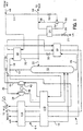
- a nitrogen generator 1 in accordance with the present invention is illustrated. Air after being filtered to remove dust particles is compressed and then purified to remove carbon dioxide and water. Thereafter, the air is cooled as air stream 10 to a temperature suitable for its rectification within a main heat exchanger 11. Air stream 10 is introduced at pressure into a distillation column 12 which is configured to produce an oxygen rich liquid as column bottoms and a high purity nitrogen-rich vapour as column overhead and which operates at a superatmospheric pressure typically in the range of 5 to 10 bar so as to enable a high pressure nitrogen product to be taken from the top of the distillation or rectification column 12.
- the oxygen-rich liquid preferably has a relatively high nitrogen content, e.g. in the range of 30 to 70% by volume, preferably 40 to 60% by volume, and may alternatively be referred to as a waste nitrogen stream.
- a nitrogen-rich stream 14 is produced from the nitrogen-rich vapour.
- a part 16 of the nitrogen-rich stream 14 is condensed within a head condenser 18 to produce a condensed stream 20.
- a part 22 of the condensed stream is re-introduced back into distillation column 12.
- Another part, which in the illustrated embodiment is a remaining part of the condensed stream 20, is extracted as a liquid product stream 23 which preferably after having been subcooled within a subcooling unit 24 is expanded by passage through an expansion valve 26 prior to being sent to storage, a product gaseous nitrogen product stream may, as shown, be taken from the stream of nitrogen-rich stream 14 is a possible modification of the illustrated embodiment.
- An oxygen rich liquid stream 28 is subcooled with a subcooling unit 30 and is then expanded through an expansion valve 32 to a sufficiently low temperature to effect the condensation of the part 16 of the aforesaid nitrogen-rich stream 14.
- the oxygen-rich liquid stream 28, after expansion, is introduced into head condenser 18 to produce a vaporised oxygen-rich liquid stream 34.
- a part 36 of the vaporised oxygen-rich liquid stream is re-compressed within a recycle compressor 38 and then cooled in Section 11B of main heat exchanger 11 to the temperature of distillation column 12.
- the now compressed, vaporised oxygen-rich liquid stream is re-introduced into distillation column 12.
- a remaining part 40 of vaporised oxygen-rich liquid stream 34 is warmed to an intermediate temperature, above the temperature at which the rectification of the air takes place. This occurs within Section 11 B of main heat exchanger 11.
- the remaining part 40 of oxygen-rich liquid stream forms a refrigerant stream which is expanded within a turboexpander 42 to produce a primary refrigerant stream 44.
- Turboexpander 42 is coupled to compressor 38. Part of the work of expansion is dissipated by an energy dissipative brake 46 which if desired may take the form of an electrical generator and a remaining part of the energy of expansion is used to power compressor 38.
- Primary refrigerant stream 44 warms within subcooling unit 30 and then is fully warmed within main heat exchanger 11 where it is discharged from the plant as waste.
- embodiments of the present invention are possible in which a stream of liquid is extracted at a column location above the bottom of the column and then, after vaporisation during use in the distillation process, is recompressed, cooled and reintroduced into the column. Additionally, the present invention is not limited to nitrogen generation plants in which a refrigerant stream is formed from vaporised column bottoms liquid although such generators are preferred.
- a supplemental refrigerant stream 48 is supplied from a nitrogen liquefying unit (labelled "NLU") that will be discussed hereinafter.
- NLU nitrogen liquefying unit
- a part 50 of supplementary refrigerant stream 48 is vaporised within head condenser 18 and then is further warmed within subcooling unit 30. Thereafter, it is introduced into main heat exchanger 11 where it is fully rewarmed and then returned back to the nitrogen liquefying unit.
- An embodiment of the present invention is possible in which the supplementary refrigerant stream is partly vaporised within head condenser 18 and then goes on to be fully vaporised within main heat exchanger 11.
- Supplemental refrigeration is thus supplied to nitrogen generator 1.
- a remaining part 51 of the incoming supplementary refrigerant stream is expanded by passage through a valve 52 and then is phase separated within phase separator 54 to produce a liquid stream 56.
- Liquid stream 56 acts to subcool liquid product stream 23.
- a vapour stream 58 composed of the vapour phase of the separated supplemental refrigerant is combined with stream 56 and returned to the nitrogen liquefying unit as a stream 59.
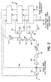
- a nitrogen liquefying unit 2 for use in association with a nitrogen generator according to the present invention is illustrated.
- Part 50 of supplementary refrigerant stream 48 is combined with a recycle stream 60 and stream 59 after having been warmed in a manner that will be discussed hereinafter.
- the resultant combined stream is then recompressed within a compression unit 62 to form a compressed stream 64.
- the heat of compression is removed from compressed stream 64 by an after-cooler 66.
- Compressed stream 64 is then introduced into a first booster compressor 68 and the heat of compression is removed by a first after-cooler 70.
- Compressed stream 64 is then introduced into a second booster compressor 72 and the heat of compression is then removed from compressed stream 64 by a second after-cooler 74.
- the major part of compressed stream 64 is cooled within a heat exchanger 76 and valve expanded to liquefaction by valve 77 to produce supplementary refrigerant stream 48.
- a subsidiary stream 78 is separated from compressed stream 64.
- Subsidiary stream 78 is expanded within a first turboexpander 80 linked to second booster compressor 72 to produce an expanded stream 82.
- compressed stream 64 is further cooled and a subsidiary stream 84 is then separated therefrom.
- Subsidiary stream 84 is expanded within a second turboexpander 86 operating at a lower temperature than that of first turboexpander 80.
- Second turboexpander 86 is linked to first compressor booster 68.
- the resultant expanded stream 88 is then partly rewarmed within heat exchanger 76 and combined with expanded stream 82 to form recycle stream 60.
- Recycle stream 60 is fully rewarmed within main heat exchanger 76 prior to its combination with the part 50 of supplemental refrigerant stream 48 that . enters liquefying unit 2.
- Stream 59 also fully warms within heat exchanger unit 76 and is then compressed in a compressor 90 to enable it to also combine with part 50 of supplemental refrigerant stream 48.
Landscapes
- Engineering & Computer Science (AREA)
- Physics & Mathematics (AREA)
- Mechanical Engineering (AREA)
- Thermal Sciences (AREA)
- General Engineering & Computer Science (AREA)
- Separation By Low-Temperature Treatments (AREA)
Claims (9)
- Procédé de production d'azote, ledit procédé comprenant les étapes consistant à :caractérisé en ce qu 'un flux de réfrigérant supplémentaire est vaporisé puis est reliquéfié ;refroidir de l'air d'alimentation, comprimé et épuré, à une température adaptée à sa rectification ;introduire ledit air d'alimentation, comprimé et épuré, dans une colonne de distillation pour produire par rectification un produit de tête de colonne riche en azote, de pureté élevée, et un liquide riche en oxygène comme pieds de colonne ;condenser une fraction au moins d'un flux riche en azote composé dudit produit de tête de colonne riche en azote et introduire une fraction du condensat résultant comme reflux dans ladite colonne de distillation ;former un flux de produit azote à partir d'une fraction restante du condensat résultant ;comprimer un flux de recyclage, refroidir ledit flux de recyclage à ladite température et introduire ledit flux de recyclage dans ladite colonne de distillation ;détendre un flux de réfrigérant avec la réalisation d'un travail pour former un flux de réfrigérant principal et échanger indirectement de la chaleur entre ledit flux de réfrigérant principal et ledit flux d'air comprimé et épuré et ledit flux de recyclage ;appliquer une partie dudit travail à ladite compression dudit flux de recyclage ;ledit flux de réfrigérant supplémentaire étant au moins partiellement vaporisé par échange indirect de chaleur avec ladite au moins une fraction dudit flux riche en azote, afin ainsi d'aider à réaliser ladite condensation de ladite fraction dudit flux riche en azote ; etavant ladite re-liquéfaction dudit flux de réfrigérant supplémentaire, un échange indirect de chaleur étant réalisé entre ledit flux de réfrigérant supplémentaire et ledit air comprimé et épuré et ledit flux de recyclage.
- Procédé selon la Revendication 1, dans lequel :un flux dudit liquide riche en oxygène est soutiré de ladite colonne de distillation, détendu dans une vanne, et envoyé en échange indirect de chaleur avec ledit flux riche en azote pour aider à condenser ladite au moins une fraction dudit flux riche en azote et ainsi former un flux vaporisé riche en oxygène ;ledit flux de recyclage est formé d'une fraction dudit flux vaporisé riche en oxygène ; etledit flux de réfrigérant est formé d'une fraction restante dudit flux vaporisé de liquide riche en oxygène.
- Procédé selon la Revendication 2, dans lequel ledit flux de réfrigérant supplémentaire est vaporisé en totalité par ledit échange indirect de chaleur avec ledit produit de tête de colonne riche en azote.
- Procédé selon la Revendication 3, dans lequel ledit flux de réfrigérant supplémentaire est liquéfié par compression dudit flux de réfrigérant supplémentaire et détente dudit flux de réfrigérant supplémentaire à deux niveaux de température.
- Procédé selon la Revendication 2, dans lequel :ledit produit azote comprend une fraction dudit condensat et est divisé en deux flux de produit ;l'un desdits flux de produit est vaporisé par échange indirect de chaleur avec ledit air comprimé et épuré ;l'autre desdits flux de produit est sous-refroidi par échange indirect de chaleur avec un flux auxiliaire composé d'une fraction dudit flux de réfrigérant supplémentaire ; etledit flux auxiliaire est combiné avec une fraction restante dudit flux de réfrigérant supplémentaire avant liquéfaction.
- Générateur d'azote comprenant :caractérisé en ce qu'il comprenddes moyens d'échange de chaleur principaux configurés pour refroidir de l'air d'alimentation comprimé et épuré à une température adaptée à sa rectification ;une colonne de distillation communiquant avec lesdits moyens d'échange de chaleur principaux, pour rectifier ledit air d'alimentation comprimé et épuré et produire ainsi un produit de tête de colonne riche en azote, de pureté élevée, et un liquide riche en oxygène comme pieds de colonne ;un condenseur de tête raccordé à ladite colonne de distillation, destiné à condenser au moins une fraction d'un flux riche en azote composé dudit produit de tête de colonne riche en azote, et à réintroduire une fraction dudit condensat résultant en retour dans ladite colonne de distillation en tant que reflux, afin qu'une fraction restante du condensat résultant puisse être extraite en tant que flux de produit ;un compresseur pour comprimer un flux de recyclage ;lesdits moyens d'échange de chaleur principaux étant dans une position intermédiaire entre ledit compresseur et ladite colonne de distillation afin que ledit flux de recyclage se refroidisse à ladite température et soit introduit dans ladite colonne de distillation pour augmenter la récupération dudit produit azote ;une turbine de détente pour détendre un flux de réfrigérant avec réalisation d'un travail, pour former un flux de réfrigérant principal ;ladite turbine de détente étant en communication avec lesdits moyens d'échange de chaleur principaux afin que ledit flux de réfrigérant principal échange indirectement de la chaleur avec ledit air comprimé et épuré ; etdes moyens pour coupler ladite turbine de détente audit compresseur afin qu'une partie dudit travail soit appliquée à ladite compression dudit flux de recyclage ;un circuit de réfrigérant supplémentaire pour faire circuler un flux de réfrigérant supplémentaire vaporisé pendant la circulation, ledit circuit de réfrigérant supplémentaire englobantledit condenseur de tête, ledit condenseur de tête étant configuré de façon que ledit flux de réfrigérant supplémentaire soit au moins partiellement vaporisé par échange indirect de chaleur avec ladite au moins une fraction du flux riche en azote,lesdits moyens d'échange de chaleur principaux, lesdits moyens d'échange de chaleur principaux étant aussi configurés pour un échange indirect de chaleur entre le flux de réfrigérant supplémentaire et ledit air comprimé et épuré ; etun liquéfacteur dans une position située entre lesdits moyens d'échange de chaleur principaux et ledit condenseur de tête pour re-liquéfier le flux de réfrigérant supplémentaire vaporisé.
- Générateur d'azote selon la Revendication 6, dans lequel ledit condenseur de tête est également configuré pour un échange indirect de chaleur avec un flux dudit liquide riche en oxygène ; englobant additionnellementune vanne de détente placée entre ledit condenseur de tête et ladite colonne de distillation pour détente par la vanne dudit flux dudit liquide riche en oxygène, afin de former ainsi un flux vaporisé riche en oxygène ; et dans lequelledit compresseur et ladite turbine de détente communiquent avec ledit condenseur de tête afin que ledit flux de recyclage comprenne une fraction dudit flux vaporisé de liquide riche en oxygène et ledit flux de réfrigérant comprenne une fraction restante dudit flux vaporisé de liquide riche en oxygène.
- Générateur d'azote selon la Revendication 6 ou la Revendication 7, dans lequel ledit liquéfacteur du flux de réfrigérant supplémentaire comprend un liquéfacteur d'azote ayant deux turbines de détente fonctionnant à deux niveaux de température différents.
- Générateur d'azote selon l'une quelconque des Revendications précédentes, dans lequel le compresseur de recyclage est couplé à la turbine de détente par l'intermédiaire d'un détendeur à dispersion d'énergie.
Applications Claiming Priority (2)
| Application Number | Priority Date | Filing Date | Title |
|---|---|---|---|
| US08/573,838 US5611218A (en) | 1995-12-18 | 1995-12-18 | Nitrogen generation method and apparatus |
| US573838 | 2000-05-18 |
Publications (3)
| Publication Number | Publication Date |
|---|---|
| EP0780648A2 EP0780648A2 (fr) | 1997-06-25 |
| EP0780648A3 EP0780648A3 (fr) | 1998-02-04 |
| EP0780648B1 true EP0780648B1 (fr) | 2001-08-29 |
Family
ID=24293594
Family Applications (1)
| Application Number | Title | Priority Date | Filing Date |
|---|---|---|---|
| EP96309185A Expired - Lifetime EP0780648B1 (fr) | 1995-12-18 | 1996-12-17 | Procédé et dispositif de production d'azote |
Country Status (16)
| Country | Link |
|---|---|
| US (1) | US5611218A (fr) |
| EP (1) | EP0780648B1 (fr) |
| JP (1) | JP3938797B2 (fr) |
| KR (1) | KR100191987B1 (fr) |
| CN (1) | CN1141547C (fr) |
| AU (1) | AU725907B2 (fr) |
| CA (1) | CA2187494A1 (fr) |
| DE (1) | DE69614815T2 (fr) |
| IL (1) | IL119333A (fr) |
| MX (1) | MX9605403A (fr) |
| MY (1) | MY113546A (fr) |
| PL (1) | PL317512A1 (fr) |
| SG (1) | SG44978A1 (fr) |
| TR (1) | TR199600831A2 (fr) |
| TW (1) | TW338025B (fr) |
| ZA (1) | ZA968399B (fr) |
Cited By (3)
| Publication number | Priority date | Publication date | Assignee | Title |
|---|---|---|---|---|
| EP2053330A1 (fr) | 2007-10-25 | 2009-04-29 | Linde Aktiengesellschaft | Procédé de séparation de l'air à basse température |
| EP2053331A1 (fr) | 2007-10-25 | 2009-04-29 | Linde Aktiengesellschaft | Procédé et dispositif de séparation de l'air à basse température |
| EP2789958A1 (fr) | 2013-04-10 | 2014-10-15 | Linde Aktiengesellschaft | Procédé de décomposition à basse température de l'air et installation de décomposition de l'air |
Families Citing this family (16)
| Publication number | Priority date | Publication date | Assignee | Title |
|---|---|---|---|---|
| US7081153B2 (en) * | 2003-12-02 | 2006-07-25 | Honeywell International Inc. | Gas generating system and method for inerting aircraft fuel tanks |
| DE102006039616B3 (de) * | 2006-08-24 | 2008-04-03 | Eberhard Otten | Verfahren und Vorrichtung zur Speicherung von Brenngas, insbesondere Erdgas |
| US8429933B2 (en) * | 2007-11-14 | 2013-04-30 | Praxair Technology, Inc. | Method for varying liquid production in an air separation plant with use of a variable speed turboexpander |
| US20090320520A1 (en) * | 2008-06-30 | 2009-12-31 | David Ross Parsnick | Nitrogen liquefier retrofit for an air separation plant |
| US9526933B2 (en) | 2008-09-15 | 2016-12-27 | Engineered Corrosion Solutions, Llc | High nitrogen and other inert gas anti-corrosion protection in wet pipe fire protection system |
| US12161900B2 (en) | 2008-09-15 | 2024-12-10 | Engineered Corrosion Solutions, Llc | Adjustable inert gas generation assembly for water-based fire protection systems |
| US9144700B2 (en) | 2008-09-15 | 2015-09-29 | Engineered Corrosion Solutions, Llc | Fire protection systems having reduced corrosion |
| DE102008064117A1 (de) | 2008-12-19 | 2009-05-28 | Linde Ag | Verfahren und Vorrichtung zur Tieftemperaturzerlegung von Luft |
| CN101492156B (zh) * | 2009-03-12 | 2010-12-29 | 四川空分设备(集团)有限责任公司 | 低能耗制氮方法和装置 |
| EP2236964B1 (fr) | 2009-03-24 | 2019-11-20 | Linde AG | Procédé et dispositif de séparation de l'air à basse température |
| US8720591B2 (en) | 2009-10-27 | 2014-05-13 | Engineered Corrosion Solutions, Llc | Controlled discharge gas vent |
| US9726427B1 (en) | 2010-05-19 | 2017-08-08 | Cosmodyne, LLC | Liquid nitrogen production |
| WO2013181596A1 (fr) | 2012-05-31 | 2013-12-05 | Engineered Corrosion Solutions, Llc | Events de gaz actionnés électriquement pour des systèmes d'extincteurs à eau du type sprinkleur et procédés associés |
| WO2016131060A1 (fr) | 2015-02-14 | 2016-08-18 | Tyco Fire Products Lp | Protection contre l'incendie à base de brouillard d'eau pour espaces interstitiels à ventilation forcée |
| US10391344B2 (en) | 2017-02-08 | 2019-08-27 | Agf Manufacturing Inc. | Purge and vent valve assembly |
| AU2018269511A1 (en) * | 2017-05-16 | 2019-11-28 | Terrence J. Ebert | Apparatus and process for liquefying gases |
Family Cites Families (9)
| Publication number | Priority date | Publication date | Assignee | Title |
|---|---|---|---|---|
| GB975729A (en) * | 1963-11-12 | 1964-11-18 | Conch Int Methane Ltd | Process for the separation of nitrogen and oxygen from air by fractional distillation |
| US3370435A (en) * | 1965-07-29 | 1968-02-27 | Air Prod & Chem | Process for separating gaseous mixtures |
| US4375367A (en) * | 1981-04-20 | 1983-03-01 | Air Products And Chemicals, Inc. | Lower power, freon refrigeration assisted air separation |
| GB2126700B (en) * | 1982-09-15 | 1985-12-18 | Petrocarbon Dev Ltd | Improvements in the production of pure nitrogen |
| US4655809A (en) * | 1986-01-10 | 1987-04-07 | Air Products And Chemicals, Inc. | Air separation process with single distillation column with segregated heat pump cycle |
| US5006137A (en) * | 1990-03-09 | 1991-04-09 | Air Products And Chemicals, Inc. | Nitrogen generator with dual reboiler/condensers in the low pressure distillation column |
| US5275003A (en) * | 1992-07-20 | 1994-01-04 | Air Products And Chemicals, Inc. | Hybrid air and nitrogen recycle liquefier |
| US5311744A (en) * | 1992-12-16 | 1994-05-17 | The Boc Group, Inc. | Cryogenic air separation process and apparatus |
| US5363657A (en) * | 1993-05-13 | 1994-11-15 | The Boc Group, Inc. | Single column process and apparatus for producing oxygen at above-atmospheric pressure |
-
1995
- 1995-12-18 US US08/573,838 patent/US5611218A/en not_active Expired - Lifetime
-
1996
- 1996-09-30 IL IL11933396A patent/IL119333A/xx not_active IP Right Cessation
- 1996-10-02 AU AU67979/96A patent/AU725907B2/en not_active Ceased
- 1996-10-03 SG SG1996010781A patent/SG44978A1/en unknown
- 1996-10-04 TW TW085112165A patent/TW338025B/zh not_active IP Right Cessation
- 1996-10-04 ZA ZA968399A patent/ZA968399B/xx unknown
- 1996-10-09 CA CA002187494A patent/CA2187494A1/fr not_active Abandoned
- 1996-10-22 TR TR96/00831A patent/TR199600831A2/xx unknown
- 1996-11-06 MX MX9605403A patent/MX9605403A/es unknown
- 1996-12-04 JP JP32390096A patent/JP3938797B2/ja not_active Expired - Fee Related
- 1996-12-16 PL PL96317512A patent/PL317512A1/xx unknown
- 1996-12-17 MY MYPI96005312A patent/MY113546A/en unknown
- 1996-12-17 KR KR1019960066685A patent/KR100191987B1/ko not_active Expired - Fee Related
- 1996-12-17 DE DE69614815T patent/DE69614815T2/de not_active Expired - Lifetime
- 1996-12-17 EP EP96309185A patent/EP0780648B1/fr not_active Expired - Lifetime
- 1996-12-18 CN CNB961232692A patent/CN1141547C/zh not_active Expired - Fee Related
Cited By (4)
| Publication number | Priority date | Publication date | Assignee | Title |
|---|---|---|---|---|
| EP2053330A1 (fr) | 2007-10-25 | 2009-04-29 | Linde Aktiengesellschaft | Procédé de séparation de l'air à basse température |
| EP2053331A1 (fr) | 2007-10-25 | 2009-04-29 | Linde Aktiengesellschaft | Procédé et dispositif de séparation de l'air à basse température |
| DE102007051184A1 (de) | 2007-10-25 | 2009-04-30 | Linde Aktiengesellschaft | Verfahren und Vorrichtung zur Tieftemperatur-Luftzerlegung |
| EP2789958A1 (fr) | 2013-04-10 | 2014-10-15 | Linde Aktiengesellschaft | Procédé de décomposition à basse température de l'air et installation de décomposition de l'air |
Also Published As
| Publication number | Publication date |
|---|---|
| ZA968399B (en) | 1997-05-13 |
| SG44978A1 (en) | 1997-12-19 |
| KR970047715A (ko) | 1997-07-26 |
| CN1141547C (zh) | 2004-03-10 |
| MY113546A (en) | 2002-03-30 |
| IL119333A0 (en) | 1996-12-05 |
| MX9605403A (es) | 1997-06-28 |
| EP0780648A3 (fr) | 1998-02-04 |
| DE69614815D1 (de) | 2001-10-04 |
| TW338025B (en) | 1998-08-11 |
| TR199600831A2 (tr) | 1997-07-21 |
| AU725907B2 (en) | 2000-10-26 |
| EP0780648A2 (fr) | 1997-06-25 |
| JP3938797B2 (ja) | 2007-06-27 |
| AU6797996A (en) | 1997-06-26 |
| JPH09269189A (ja) | 1997-10-14 |
| US5611218A (en) | 1997-03-18 |
| CA2187494A1 (fr) | 1997-06-19 |
| DE69614815T2 (de) | 2002-04-11 |
| KR100191987B1 (ko) | 1999-06-15 |
| CN1163386A (zh) | 1997-10-29 |
| IL119333A (en) | 2000-07-16 |
| PL317512A1 (en) | 1997-06-23 |
Similar Documents
| Publication | Publication Date | Title |
|---|---|---|
| US5611218A (en) | Nitrogen generation method and apparatus | |
| EP0644388B1 (fr) | Séparation cryogénique d'air | |
| CA2131655C (fr) | Methodes de separation de l'air pour la coproduction d'oxygene et d'azote en phases gazeuse ou liquide | |
| US5582034A (en) | Air separation method and apparatus for producing nitrogen | |
| US4705548A (en) | Liquid products using an air and a nitrogen recycle liquefier | |
| US4715873A (en) | Liquefied gases using an air recycle liquefier | |
| US4615716A (en) | Process for producing ultra high purity oxygen | |
| US4702757A (en) | Dual air pressure cycle to produce low purity oxygen | |
| CA2068181C (fr) | Procede haute pression de separation d'air avec production de liquide | |
| US4543115A (en) | Dual feed air pressure nitrogen generator cycle | |
| US4783210A (en) | Air separation process with modified single distillation column nitrogen generator | |
| US5363657A (en) | Single column process and apparatus for producing oxygen at above-atmospheric pressure | |
| MXPA96005403A (en) | Nitrogen generation method and apparatus | |
| CA2206649C (fr) | Methode et appareil pour l'obtention de produits liquides a partir de l'air, en diverses proportions | |
| US4834785A (en) | Cryogenic nitrogen generator with nitrogen expander | |
| US5528906A (en) | Method and apparatus for producing ultra-high purity oxygen | |
| JPH07151462A (ja) | 高圧の酸素及び窒素製品を製造する圧縮原料空気の低温分離法 | |
| EP0381319A1 (fr) | Dispositif et procédé de séparation d'air | |
| CA2202010C (fr) | Methode et appareil pour le fractionnement de l'air | |
| US5934106A (en) | Apparatus and method for producing nitrogen | |
| AU3253700A (en) | Separation of air | |
| US4869742A (en) | Air separation process with waste recycle for nitrogen and oxygen production | |
| US5868006A (en) | Air separation method and apparatus for producing nitrogen | |
| EP0709632B1 (fr) | Procédé et dispositif pour la production d'azote par séparation d'air | |
| RU96122398A (ru) | Способ и устройство для производства азота |
Legal Events
| Date | Code | Title | Description |
|---|---|---|---|
| PUAI | Public reference made under article 153(3) epc to a published international application that has entered the european phase |
Free format text: ORIGINAL CODE: 0009012 |
|
| AK | Designated contracting states |
Kind code of ref document: A2 Designated state(s): BE DE FR GB IE IT LU NL SE |
|
| PUAL | Search report despatched |
Free format text: ORIGINAL CODE: 0009013 |
|
| AK | Designated contracting states |
Kind code of ref document: A3 Designated state(s): BE DE FR GB IE IT LU NL SE |
|
| 17P | Request for examination filed |
Effective date: 19980707 |
|
| GRAG | Despatch of communication of intention to grant |
Free format text: ORIGINAL CODE: EPIDOS AGRA |
|
| 17Q | First examination report despatched |
Effective date: 20000825 |
|
| GRAG | Despatch of communication of intention to grant |
Free format text: ORIGINAL CODE: EPIDOS AGRA |
|
| GRAG | Despatch of communication of intention to grant |
Free format text: ORIGINAL CODE: EPIDOS AGRA |
|
| GRAH | Despatch of communication of intention to grant a patent |
Free format text: ORIGINAL CODE: EPIDOS IGRA |
|
| GRAH | Despatch of communication of intention to grant a patent |
Free format text: ORIGINAL CODE: EPIDOS IGRA |
|
| GRAA | (expected) grant |
Free format text: ORIGINAL CODE: 0009210 |
|
| AK | Designated contracting states |
Kind code of ref document: B1 Designated state(s): BE DE FR GB IE IT LU NL SE |
|
| PG25 | Lapsed in a contracting state [announced via postgrant information from national office to epo] |
Ref country code: NL Free format text: LAPSE BECAUSE OF FAILURE TO SUBMIT A TRANSLATION OF THE DESCRIPTION OR TO PAY THE FEE WITHIN THE PRESCRIBED TIME-LIMIT Effective date: 20010829 Ref country code: IT Free format text: LAPSE BECAUSE OF FAILURE TO SUBMIT A TRANSLATION OF THE DESCRIPTION OR TO PAY THE FEE WITHIN THE PRESCRIBED TIME-LIMIT;WARNING: LAPSES OF ITALIAN PATENTS WITH EFFECTIVE DATE BEFORE 2007 MAY HAVE OCCURRED AT ANY TIME BEFORE 2007. THE CORRECT EFFECTIVE DATE MAY BE DIFFERENT FROM THE ONE RECORDED. Effective date: 20010829 Ref country code: BE Free format text: LAPSE BECAUSE OF FAILURE TO SUBMIT A TRANSLATION OF THE DESCRIPTION OR TO PAY THE FEE WITHIN THE PRESCRIBED TIME-LIMIT Effective date: 20010829 |
|
| REG | Reference to a national code |
Ref country code: IE Ref legal event code: FG4D |
|
| REF | Corresponds to: |
Ref document number: 69614815 Country of ref document: DE Date of ref document: 20011004 |
|
| PG25 | Lapsed in a contracting state [announced via postgrant information from national office to epo] |
Ref country code: SE Free format text: LAPSE BECAUSE OF FAILURE TO SUBMIT A TRANSLATION OF THE DESCRIPTION OR TO PAY THE FEE WITHIN THE PRESCRIBED TIME-LIMIT Effective date: 20011129 |
|
| PGFP | Annual fee paid to national office [announced via postgrant information from national office to epo] |
Ref country code: SE Payment date: 20011203 Year of fee payment: 6 |
|
| PGFP | Annual fee paid to national office [announced via postgrant information from national office to epo] |
Ref country code: LU Payment date: 20011213 Year of fee payment: 6 |
|
| PGFP | Annual fee paid to national office [announced via postgrant information from national office to epo] |
Ref country code: BE Payment date: 20011224 Year of fee payment: 6 |
|
| REG | Reference to a national code |
Ref country code: GB Ref legal event code: IF02 |
|
| ET | Fr: translation filed | ||
| NLV1 | Nl: lapsed or annulled due to failure to fulfill the requirements of art. 29p and 29m of the patents act | ||
| PLBE | No opposition filed within time limit |
Free format text: ORIGINAL CODE: 0009261 |
|
| STAA | Information on the status of an ep patent application or granted ep patent |
Free format text: STATUS: NO OPPOSITION FILED WITHIN TIME LIMIT |
|
| 26N | No opposition filed | ||
| PG25 | Lapsed in a contracting state [announced via postgrant information from national office to epo] |
Ref country code: LU Free format text: LAPSE BECAUSE OF NON-PAYMENT OF DUE FEES Effective date: 20021217 |
|
| PGFP | Annual fee paid to national office [announced via postgrant information from national office to epo] |
Ref country code: GB Payment date: 20101215 Year of fee payment: 15 |
|
| PGFP | Annual fee paid to national office [announced via postgrant information from national office to epo] |
Ref country code: DE Payment date: 20101215 Year of fee payment: 15 |
|
| PGFP | Annual fee paid to national office [announced via postgrant information from national office to epo] |
Ref country code: FR Payment date: 20111219 Year of fee payment: 16 Ref country code: IE Payment date: 20111212 Year of fee payment: 16 |
|
| GBPC | Gb: european patent ceased through non-payment of renewal fee |
Effective date: 20121217 |
|
| REG | Reference to a national code |
Ref country code: IE Ref legal event code: MM4A |
|
| REG | Reference to a national code |
Ref country code: FR Ref legal event code: ST Effective date: 20130830 |
|
| REG | Reference to a national code |
Ref country code: DE Ref legal event code: R119 Ref document number: 69614815 Country of ref document: DE Effective date: 20130702 |
|
| PG25 | Lapsed in a contracting state [announced via postgrant information from national office to epo] |
Ref country code: DE Free format text: LAPSE BECAUSE OF NON-PAYMENT OF DUE FEES Effective date: 20130702 Ref country code: IE Free format text: LAPSE BECAUSE OF NON-PAYMENT OF DUE FEES Effective date: 20121217 |
|
| PG25 | Lapsed in a contracting state [announced via postgrant information from national office to epo] |
Ref country code: FR Free format text: LAPSE BECAUSE OF NON-PAYMENT OF DUE FEES Effective date: 20130102 Ref country code: GB Free format text: LAPSE BECAUSE OF NON-PAYMENT OF DUE FEES Effective date: 20121217 |