EP2053331A1 - Procédé et dispositif de séparation de l'air à basse température - Google Patents
Procédé et dispositif de séparation de l'air à basse température Download PDFInfo
- Publication number
- EP2053331A1 EP2053331A1 EP08017993A EP08017993A EP2053331A1 EP 2053331 A1 EP2053331 A1 EP 2053331A1 EP 08017993 A EP08017993 A EP 08017993A EP 08017993 A EP08017993 A EP 08017993A EP 2053331 A1 EP2053331 A1 EP 2053331A1
- Authority
- EP
- European Patent Office
- Prior art keywords
- residual fraction
- single column
- column
- heat exchanger
- main heat
- Prior art date
- Legal status (The legal status is an assumption and is not a legal conclusion. Google has not performed a legal analysis and makes no representation as to the accuracy of the status listed.)
- Withdrawn
Links
- 238000000034 method Methods 0.000 title claims abstract description 28
- 238000000926 separation method Methods 0.000 title claims abstract description 8
- 239000001301 oxygen Substances 0.000 claims abstract description 36
- 229910052760 oxygen Inorganic materials 0.000 claims abstract description 36
- QVGXLLKOCUKJST-UHFFFAOYSA-N atomic oxygen Chemical compound [O] QVGXLLKOCUKJST-UHFFFAOYSA-N 0.000 claims description 34
- MYMOFIZGZYHOMD-UHFFFAOYSA-N Dioxygen Chemical compound O=O MYMOFIZGZYHOMD-UHFFFAOYSA-N 0.000 claims description 24
- IJGRMHOSHXDMSA-UHFFFAOYSA-N Atomic nitrogen Chemical compound N#N IJGRMHOSHXDMSA-UHFFFAOYSA-N 0.000 claims description 20
- 239000007788 liquid Substances 0.000 claims description 15
- 229910052757 nitrogen Inorganic materials 0.000 claims description 10
- 238000004519 manufacturing process Methods 0.000 claims description 4
- 238000004821 distillation Methods 0.000 claims description 3
- 238000001816 cooling Methods 0.000 claims description 2
- 238000011084 recovery Methods 0.000 claims description 2
- 239000012530 fluid Substances 0.000 abstract 4
- 230000006837 decompression Effects 0.000 abstract 3
- 239000000047 product Substances 0.000 description 33
- 230000002349 favourable effect Effects 0.000 description 7
- 239000007789 gas Substances 0.000 description 7
- 230000006835 compression Effects 0.000 description 4
- 238000007906 compression Methods 0.000 description 4
- 238000011144 upstream manufacturing Methods 0.000 description 4
- 238000004140 cleaning Methods 0.000 description 3
- 238000010438 heat treatment Methods 0.000 description 3
- XKRFYHLGVUSROY-UHFFFAOYSA-N Argon Chemical compound [Ar] XKRFYHLGVUSROY-UHFFFAOYSA-N 0.000 description 2
- 238000002485 combustion reaction Methods 0.000 description 2
- 238000001704 evaporation Methods 0.000 description 2
- 239000012263 liquid product Substances 0.000 description 2
- 239000000203 mixture Substances 0.000 description 2
- 238000005057 refrigeration Methods 0.000 description 2
- 230000008929 regeneration Effects 0.000 description 2
- 238000011069 regeneration method Methods 0.000 description 2
- 239000002689 soil Substances 0.000 description 2
- 238000001179 sorption measurement Methods 0.000 description 2
- 238000001228 spectrum Methods 0.000 description 2
- 241000883306 Huso huso Species 0.000 description 1
- 102000017795 Perilipin-1 Human genes 0.000 description 1
- 108010067162 Perilipin-1 Proteins 0.000 description 1
- 229910052786 argon Inorganic materials 0.000 description 1
- 230000005540 biological transmission Effects 0.000 description 1
- 238000006243 chemical reaction Methods 0.000 description 1
- 239000007795 chemical reaction product Substances 0.000 description 1
- 238000005056 compaction Methods 0.000 description 1
- 238000000354 decomposition reaction Methods 0.000 description 1
- 230000008020 evaporation Effects 0.000 description 1
- -1 for example Substances 0.000 description 1
- 229910021485 fumed silica Inorganic materials 0.000 description 1
- 239000012535 impurity Substances 0.000 description 1
- 238000011065 in-situ storage Methods 0.000 description 1
- 239000000463 material Substances 0.000 description 1
- 239000002808 molecular sieve Substances 0.000 description 1
- QJGQUHMNIGDVPM-OUBTZVSYSA-N nitrogen-15 Chemical compound [15N] QJGQUHMNIGDVPM-OUBTZVSYSA-N 0.000 description 1
- 239000007800 oxidant agent Substances 0.000 description 1
- 230000001590 oxidative effect Effects 0.000 description 1
- 230000002265 prevention Effects 0.000 description 1
- 238000005086 pumping Methods 0.000 description 1
- 238000010992 reflux Methods 0.000 description 1
- 239000004065 semiconductor Substances 0.000 description 1
- URGAHOPLAPQHLN-UHFFFAOYSA-N sodium aluminosilicate Chemical compound [Na+].[Al+3].[O-][Si]([O-])=O.[O-][Si]([O-])=O URGAHOPLAPQHLN-UHFFFAOYSA-N 0.000 description 1
- XLYOFNOQVPJJNP-UHFFFAOYSA-N water Substances O XLYOFNOQVPJJNP-UHFFFAOYSA-N 0.000 description 1
Images

Classifications
-
- B—PERFORMING OPERATIONS; TRANSPORTING
- B01—PHYSICAL OR CHEMICAL PROCESSES OR APPARATUS IN GENERAL
- B01D—SEPARATION
- B01D3/00—Distillation or related exchange processes in which liquids are contacted with gaseous media, e.g. stripping
-
- F—MECHANICAL ENGINEERING; LIGHTING; HEATING; WEAPONS; BLASTING
- F25—REFRIGERATION OR COOLING; COMBINED HEATING AND REFRIGERATION SYSTEMS; HEAT PUMP SYSTEMS; MANUFACTURE OR STORAGE OF ICE; LIQUEFACTION SOLIDIFICATION OF GASES
- F25J—LIQUEFACTION, SOLIDIFICATION OR SEPARATION OF GASES OR GASEOUS OR LIQUEFIED GASEOUS MIXTURES BY PRESSURE AND COLD TREATMENT OR BY BRINGING THEM INTO THE SUPERCRITICAL STATE
- F25J3/00—Processes or apparatus for separating the constituents of gaseous or liquefied gaseous mixtures involving the use of liquefaction or solidification
- F25J3/02—Processes or apparatus for separating the constituents of gaseous or liquefied gaseous mixtures involving the use of liquefaction or solidification by rectification, i.e. by continuous interchange of heat and material between a vapour stream and a liquid stream
- F25J3/04—Processes or apparatus for separating the constituents of gaseous or liquefied gaseous mixtures involving the use of liquefaction or solidification by rectification, i.e. by continuous interchange of heat and material between a vapour stream and a liquid stream for air
- F25J3/04248—Generation of cold for compensating heat leaks or liquid production, e.g. by Joule-Thompson expansion
- F25J3/04254—Generation of cold for compensating heat leaks or liquid production, e.g. by Joule-Thompson expansion using the cold stored in external cryogenic fluids
- F25J3/0426—The cryogenic component does not participate in the fractionation
-
- B—PERFORMING OPERATIONS; TRANSPORTING
- B01—PHYSICAL OR CHEMICAL PROCESSES OR APPARATUS IN GENERAL
- B01D—SEPARATION
- B01D1/00—Evaporating
-
- F—MECHANICAL ENGINEERING; LIGHTING; HEATING; WEAPONS; BLASTING
- F25—REFRIGERATION OR COOLING; COMBINED HEATING AND REFRIGERATION SYSTEMS; HEAT PUMP SYSTEMS; MANUFACTURE OR STORAGE OF ICE; LIQUEFACTION SOLIDIFICATION OF GASES
- F25J—LIQUEFACTION, SOLIDIFICATION OR SEPARATION OF GASES OR GASEOUS OR LIQUEFIED GASEOUS MIXTURES BY PRESSURE AND COLD TREATMENT OR BY BRINGING THEM INTO THE SUPERCRITICAL STATE
- F25J3/00—Processes or apparatus for separating the constituents of gaseous or liquefied gaseous mixtures involving the use of liquefaction or solidification
- F25J3/02—Processes or apparatus for separating the constituents of gaseous or liquefied gaseous mixtures involving the use of liquefaction or solidification by rectification, i.e. by continuous interchange of heat and material between a vapour stream and a liquid stream
- F25J3/04—Processes or apparatus for separating the constituents of gaseous or liquefied gaseous mixtures involving the use of liquefaction or solidification by rectification, i.e. by continuous interchange of heat and material between a vapour stream and a liquid stream for air
- F25J3/04006—Providing pressurised feed air or process streams within or from the air fractionation unit
- F25J3/04048—Providing pressurised feed air or process streams within or from the air fractionation unit by compression of cold gaseous streams, e.g. intermediate or oxygen enriched (waste) streams
-
- F—MECHANICAL ENGINEERING; LIGHTING; HEATING; WEAPONS; BLASTING
- F25—REFRIGERATION OR COOLING; COMBINED HEATING AND REFRIGERATION SYSTEMS; HEAT PUMP SYSTEMS; MANUFACTURE OR STORAGE OF ICE; LIQUEFACTION SOLIDIFICATION OF GASES
- F25J—LIQUEFACTION, SOLIDIFICATION OR SEPARATION OF GASES OR GASEOUS OR LIQUEFIED GASEOUS MIXTURES BY PRESSURE AND COLD TREATMENT OR BY BRINGING THEM INTO THE SUPERCRITICAL STATE
- F25J3/00—Processes or apparatus for separating the constituents of gaseous or liquefied gaseous mixtures involving the use of liquefaction or solidification
- F25J3/02—Processes or apparatus for separating the constituents of gaseous or liquefied gaseous mixtures involving the use of liquefaction or solidification by rectification, i.e. by continuous interchange of heat and material between a vapour stream and a liquid stream
- F25J3/04—Processes or apparatus for separating the constituents of gaseous or liquefied gaseous mixtures involving the use of liquefaction or solidification by rectification, i.e. by continuous interchange of heat and material between a vapour stream and a liquid stream for air
- F25J3/04006—Providing pressurised feed air or process streams within or from the air fractionation unit
- F25J3/04078—Providing pressurised feed air or process streams within or from the air fractionation unit providing pressurized products by liquid compression and vaporisation with cold recovery, i.e. so-called internal compression
- F25J3/0409—Providing pressurised feed air or process streams within or from the air fractionation unit providing pressurized products by liquid compression and vaporisation with cold recovery, i.e. so-called internal compression of oxygen
-
- F—MECHANICAL ENGINEERING; LIGHTING; HEATING; WEAPONS; BLASTING
- F25—REFRIGERATION OR COOLING; COMBINED HEATING AND REFRIGERATION SYSTEMS; HEAT PUMP SYSTEMS; MANUFACTURE OR STORAGE OF ICE; LIQUEFACTION SOLIDIFICATION OF GASES
- F25J—LIQUEFACTION, SOLIDIFICATION OR SEPARATION OF GASES OR GASEOUS OR LIQUEFIED GASEOUS MIXTURES BY PRESSURE AND COLD TREATMENT OR BY BRINGING THEM INTO THE SUPERCRITICAL STATE
- F25J3/00—Processes or apparatus for separating the constituents of gaseous or liquefied gaseous mixtures involving the use of liquefaction or solidification
- F25J3/02—Processes or apparatus for separating the constituents of gaseous or liquefied gaseous mixtures involving the use of liquefaction or solidification by rectification, i.e. by continuous interchange of heat and material between a vapour stream and a liquid stream
- F25J3/04—Processes or apparatus for separating the constituents of gaseous or liquefied gaseous mixtures involving the use of liquefaction or solidification by rectification, i.e. by continuous interchange of heat and material between a vapour stream and a liquid stream for air
- F25J3/04248—Generation of cold for compensating heat leaks or liquid production, e.g. by Joule-Thompson expansion
- F25J3/04284—Generation of cold for compensating heat leaks or liquid production, e.g. by Joule-Thompson expansion using internal refrigeration by open-loop gas work expansion, e.g. of intermediate or oxygen enriched (waste-)streams
-
- F—MECHANICAL ENGINEERING; LIGHTING; HEATING; WEAPONS; BLASTING
- F25—REFRIGERATION OR COOLING; COMBINED HEATING AND REFRIGERATION SYSTEMS; HEAT PUMP SYSTEMS; MANUFACTURE OR STORAGE OF ICE; LIQUEFACTION SOLIDIFICATION OF GASES
- F25J—LIQUEFACTION, SOLIDIFICATION OR SEPARATION OF GASES OR GASEOUS OR LIQUEFIED GASEOUS MIXTURES BY PRESSURE AND COLD TREATMENT OR BY BRINGING THEM INTO THE SUPERCRITICAL STATE
- F25J3/00—Processes or apparatus for separating the constituents of gaseous or liquefied gaseous mixtures involving the use of liquefaction or solidification
- F25J3/02—Processes or apparatus for separating the constituents of gaseous or liquefied gaseous mixtures involving the use of liquefaction or solidification by rectification, i.e. by continuous interchange of heat and material between a vapour stream and a liquid stream
- F25J3/04—Processes or apparatus for separating the constituents of gaseous or liquefied gaseous mixtures involving the use of liquefaction or solidification by rectification, i.e. by continuous interchange of heat and material between a vapour stream and a liquid stream for air
- F25J3/04406—Processes or apparatus for separating the constituents of gaseous or liquefied gaseous mixtures involving the use of liquefaction or solidification by rectification, i.e. by continuous interchange of heat and material between a vapour stream and a liquid stream for air using a dual pressure main column system
- F25J3/0443—A main column system not otherwise provided, e.g. a modified double column flowsheet
-
- F—MECHANICAL ENGINEERING; LIGHTING; HEATING; WEAPONS; BLASTING
- F25—REFRIGERATION OR COOLING; COMBINED HEATING AND REFRIGERATION SYSTEMS; HEAT PUMP SYSTEMS; MANUFACTURE OR STORAGE OF ICE; LIQUEFACTION SOLIDIFICATION OF GASES
- F25J—LIQUEFACTION, SOLIDIFICATION OR SEPARATION OF GASES OR GASEOUS OR LIQUEFIED GASEOUS MIXTURES BY PRESSURE AND COLD TREATMENT OR BY BRINGING THEM INTO THE SUPERCRITICAL STATE
- F25J2200/00—Processes or apparatus using separation by rectification
- F25J2200/90—Details relating to column internals, e.g. structured packing, gas or liquid distribution
-
- F—MECHANICAL ENGINEERING; LIGHTING; HEATING; WEAPONS; BLASTING
- F25—REFRIGERATION OR COOLING; COMBINED HEATING AND REFRIGERATION SYSTEMS; HEAT PUMP SYSTEMS; MANUFACTURE OR STORAGE OF ICE; LIQUEFACTION SOLIDIFICATION OF GASES
- F25J—LIQUEFACTION, SOLIDIFICATION OR SEPARATION OF GASES OR GASEOUS OR LIQUEFIED GASEOUS MIXTURES BY PRESSURE AND COLD TREATMENT OR BY BRINGING THEM INTO THE SUPERCRITICAL STATE
- F25J2200/00—Processes or apparatus using separation by rectification
- F25J2200/90—Details relating to column internals, e.g. structured packing, gas or liquid distribution
- F25J2200/94—Details relating to the withdrawal point
-
- F—MECHANICAL ENGINEERING; LIGHTING; HEATING; WEAPONS; BLASTING
- F25—REFRIGERATION OR COOLING; COMBINED HEATING AND REFRIGERATION SYSTEMS; HEAT PUMP SYSTEMS; MANUFACTURE OR STORAGE OF ICE; LIQUEFACTION SOLIDIFICATION OF GASES
- F25J—LIQUEFACTION, SOLIDIFICATION OR SEPARATION OF GASES OR GASEOUS OR LIQUEFIED GASEOUS MIXTURES BY PRESSURE AND COLD TREATMENT OR BY BRINGING THEM INTO THE SUPERCRITICAL STATE
- F25J2210/00—Processes characterised by the type or other details of the feed stream
- F25J2210/42—Nitrogen
-
- F—MECHANICAL ENGINEERING; LIGHTING; HEATING; WEAPONS; BLASTING
- F25—REFRIGERATION OR COOLING; COMBINED HEATING AND REFRIGERATION SYSTEMS; HEAT PUMP SYSTEMS; MANUFACTURE OR STORAGE OF ICE; LIQUEFACTION SOLIDIFICATION OF GASES
- F25J—LIQUEFACTION, SOLIDIFICATION OR SEPARATION OF GASES OR GASEOUS OR LIQUEFIED GASEOUS MIXTURES BY PRESSURE AND COLD TREATMENT OR BY BRINGING THEM INTO THE SUPERCRITICAL STATE
- F25J2210/00—Processes characterised by the type or other details of the feed stream
- F25J2210/50—Oxygen
-
- F—MECHANICAL ENGINEERING; LIGHTING; HEATING; WEAPONS; BLASTING
- F25—REFRIGERATION OR COOLING; COMBINED HEATING AND REFRIGERATION SYSTEMS; HEAT PUMP SYSTEMS; MANUFACTURE OR STORAGE OF ICE; LIQUEFACTION SOLIDIFICATION OF GASES
- F25J—LIQUEFACTION, SOLIDIFICATION OR SEPARATION OF GASES OR GASEOUS OR LIQUEFIED GASEOUS MIXTURES BY PRESSURE AND COLD TREATMENT OR BY BRINGING THEM INTO THE SUPERCRITICAL STATE
- F25J2215/00—Processes characterised by the type or other details of the product stream
- F25J2215/50—Oxygen or special cases, e.g. isotope-mixtures or low purity O2
-
- F—MECHANICAL ENGINEERING; LIGHTING; HEATING; WEAPONS; BLASTING
- F25—REFRIGERATION OR COOLING; COMBINED HEATING AND REFRIGERATION SYSTEMS; HEAT PUMP SYSTEMS; MANUFACTURE OR STORAGE OF ICE; LIQUEFACTION SOLIDIFICATION OF GASES
- F25J—LIQUEFACTION, SOLIDIFICATION OR SEPARATION OF GASES OR GASEOUS OR LIQUEFIED GASEOUS MIXTURES BY PRESSURE AND COLD TREATMENT OR BY BRINGING THEM INTO THE SUPERCRITICAL STATE
- F25J2215/00—Processes characterised by the type or other details of the product stream
- F25J2215/50—Oxygen or special cases, e.g. isotope-mixtures or low purity O2
- F25J2215/56—Ultra high purity oxygen, i.e. generally more than 99,9% O2
-
- F—MECHANICAL ENGINEERING; LIGHTING; HEATING; WEAPONS; BLASTING
- F25—REFRIGERATION OR COOLING; COMBINED HEATING AND REFRIGERATION SYSTEMS; HEAT PUMP SYSTEMS; MANUFACTURE OR STORAGE OF ICE; LIQUEFACTION SOLIDIFICATION OF GASES
- F25J—LIQUEFACTION, SOLIDIFICATION OR SEPARATION OF GASES OR GASEOUS OR LIQUEFIED GASEOUS MIXTURES BY PRESSURE AND COLD TREATMENT OR BY BRINGING THEM INTO THE SUPERCRITICAL STATE
- F25J2220/00—Processes or apparatus involving steps for the removal of impurities
- F25J2220/50—Separating low boiling, i.e. more volatile components from oxygen, e.g. N2, Ar
-
- F—MECHANICAL ENGINEERING; LIGHTING; HEATING; WEAPONS; BLASTING
- F25—REFRIGERATION OR COOLING; COMBINED HEATING AND REFRIGERATION SYSTEMS; HEAT PUMP SYSTEMS; MANUFACTURE OR STORAGE OF ICE; LIQUEFACTION SOLIDIFICATION OF GASES
- F25J—LIQUEFACTION, SOLIDIFICATION OR SEPARATION OF GASES OR GASEOUS OR LIQUEFIED GASEOUS MIXTURES BY PRESSURE AND COLD TREATMENT OR BY BRINGING THEM INTO THE SUPERCRITICAL STATE
- F25J2245/00—Processes or apparatus involving steps for recycling of process streams
- F25J2245/02—Recycle of a stream in general, e.g. a by-pass stream
-
- F—MECHANICAL ENGINEERING; LIGHTING; HEATING; WEAPONS; BLASTING
- F25—REFRIGERATION OR COOLING; COMBINED HEATING AND REFRIGERATION SYSTEMS; HEAT PUMP SYSTEMS; MANUFACTURE OR STORAGE OF ICE; LIQUEFACTION SOLIDIFICATION OF GASES
- F25J—LIQUEFACTION, SOLIDIFICATION OR SEPARATION OF GASES OR GASEOUS OR LIQUEFIED GASEOUS MIXTURES BY PRESSURE AND COLD TREATMENT OR BY BRINGING THEM INTO THE SUPERCRITICAL STATE
- F25J2250/00—Details related to the use of reboiler-condensers
- F25J2250/02—Bath type boiler-condenser using thermo-siphon effect, e.g. with natural or forced circulation or pool boiling, i.e. core-in-kettle heat exchanger
-
- F—MECHANICAL ENGINEERING; LIGHTING; HEATING; WEAPONS; BLASTING
- F25—REFRIGERATION OR COOLING; COMBINED HEATING AND REFRIGERATION SYSTEMS; HEAT PUMP SYSTEMS; MANUFACTURE OR STORAGE OF ICE; LIQUEFACTION SOLIDIFICATION OF GASES
- F25J—LIQUEFACTION, SOLIDIFICATION OR SEPARATION OF GASES OR GASEOUS OR LIQUEFIED GASEOUS MIXTURES BY PRESSURE AND COLD TREATMENT OR BY BRINGING THEM INTO THE SUPERCRITICAL STATE
- F25J2250/00—Details related to the use of reboiler-condensers
- F25J2250/20—Boiler-condenser with multiple exchanger cores in parallel or with multiple re-boiling or condensing streams
Definitions
- the invention relates to a method for cryogenic air separation with a distillation column system for nitrogen production according to the preamble of patent claim 1.
- Examples of the type of air separation processes (SPECTRA) described in the preamble are in EP 412793 B2 .
- the first residual fraction is discharged below the discharge pressure of the expansion machine, that is usually below about atmospheric pressure, and can then be used in general only as a regeneration gas for an adsorption for cleaning the feed air.
- a second residual fraction can be withdrawn from the single column together with the first residual fraction and at least partially evaporated;
- the two residual fractions can be taken at different points of the single column and evaporated separately from each other, for example, in different passages of the top condenser of the single column.
- the invention has for its object to provide a method of the type mentioned above and a corresponding device, which are economically particularly favorable to operate.
- the entire oxygen-enriched residual gas is used, either for refrigeration by work expansion or for return to the column. If, in addition, an oxygen product is required, previously either more complicated double column processes have been used or the required oxygen has been supplied in liquid form and externally evaporated.
- the process according to the invention is more favorable than the known methods of additionally supplying impure oxygen as product.
- "Below about the inlet pressure of the expansion machine” means here that the pressure of the gaseous impure oxygen product at the outlet from the process because of the corresponding line losses must not be exactly equal to the inlet pressure of the expansion machine; decided measures for pressure change by more than 0.5 bar, for example, the relaxation in another expansion machine, but are excluded.
- the recompressor for the second residual fraction is simultaneously used as product compressor for the gaseous impure oxygen product. This can thus be delivered under a relatively high pressure.
- "Stripping off as a gaseous impure oxygen product” here means that the second part of the second residual fraction in the same composition as prevails downstream of the recompression, is withdrawn as an end product from the process, without being subjected to a further separation step.
- the gaseous impure oxygen product can be used for any application that requires a corresponding pressure without the need for a compressor, for example, as an oxidant in a chemical reaction such as combustion.
- a pressure of 1.8 bara and higher is needed there. at the use under an even higher pressure saves in the invention, a part of the effort for the compression in comparison to the non-pressurized residual gas downstream of the expansion machine.
- the impure oxygen product can be used in the invention, for example, to supply 02-enriched combustion air. Compared to the use of air, this offers a number of advantages.
- the increased oxygen content leads to an increase in the burner temperature. Since less nitrogen has to be heated and compressed, the energy expenditure is reduced.
- the burner output increases as more reactive mixture can flow through the burner.
- the first and the second part of the first residual fraction are introduced into the main heat exchanger, wherein the first part is removed at an intermediate temperature from the main heat exchanger and fed to the expansion machine and the second part is warmed at about ambient temperature and withdrawn as gaseous impure oxygen product.
- the "main heat exchanger” is preferably formed by a single heat exchanger block. For larger systems, it may be useful to realize the main heat exchanger by a plurality of parallel with respect to the temperature profile strands, which are formed by separate components. In principle, it is possible that the main heat exchanger or each of these strands is formed by two or more blocks connected in series.
- the first residual fraction can be branched immediately downstream of the top condenser into its two parts, which are then introduced separately from one another into the main heat exchanger.
- both parts will be at least partially warmed in the same passage of the main heat exchanger by the first and the second part of the first residual fraction are introduced together into the main heat exchanger.
- the second residual fraction can be warmed to about ambient temperature.
- the recompression is done in this case in the warm.
- the recompressed second residual fraction then becomes again cooled to about the operating temperature of the column before being introduced into the single column.
- the heating and re-cooling of the second residual fraction can be carried out in the main heat exchanger or in one or more other heat exchangers.
- cold compressor is meant here a compressor which is operated at an inlet temperature of less than 200 K, preferably less than 150 K, in particular between 90 and 120 K.
- the mechanical energy generated during the work-relaxing expansion can be used at least partially for recompression of the second residual fraction.
- the transmission of mechanical energy to the recompressor is done directly mechanically, for example via a common wave of expansion machine and recompressor.
- the recompressor is designed as a cold compressor, preferably only a part of the mechanical energy generated by the expansion machine is transferred to the recompressor; the rest goes to a warm braking device, z.
- a brake fan a generator or a dissipative brake.
- pure oxygen can additionally be obtained by removing an oxygen-containing stream from the single column at an intermediate point and feeding it to a pure oxygen column and removing a pure oxygen product stream in the liquid state from the lower region of the pure oxygen column, the pure oxygen product stream - optionally after Pressure increase in the liquid state in the main heat exchanger is vaporized against feed air and warmed and finally recovered as a gaseous product.
- This procedure is also referred to as "internal compression” and is used as an alternative to gaseous product compression (external compression) when the gaseous product is recovered under pressure.
- a corresponding process is - without the recovery of a gaseous impure oxygen product according to the invention - in the earlier German patent application 102007024168 and the corresponding applications in detail.
- the pure oxygen can also be delivered as a liquid product.
- evaporation here includes a pseudo-evaporation under supercritical pressure.
- the pressure at which the pure oxygen product stream is introduced into the main heat exchanger can therefore also be above the critical pressure, as can the pressure of the heat carrier, which is (pseudo) condensed against the pure oxygen product stream.
- the pure oxygen product stream is brought to an elevated pressure in the liquid state.
- a warm oxygen compressor can be dispensed with or at least made relatively small. If a decrease is required with strongly fluctuating amounts, the oxygen can be conveyed under higher than discharge pressure in a gas pressure vessel, which serves as a buffer.
- the first and second residual fractions can in principle be withdrawn together with the second from the single column, for example at the bottom (see EP 412793 B2 ). In many cases, however, it is more favorable if the second residual fraction has a higher nitrogen content than the first residual fraction. Then, the second residual fraction is withdrawn from an intermediate point of the single column, which is arranged above the sump, in particular above the point at which the first residual fraction is removed. The two residual fractions are then evaporated separately in the top condenser and fed to the recompression or work-performing expansion and product removal.
- the invention relates to a device for cryogenic air separation according to claim 9.
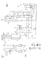
- Atmospheric air 1 is drawn in via a filter 2 from an air compressor and there compressed to an absolute pressure of 6 to 20 bar, preferably about 9 bar.
- the compressed air 6 is cleaned in a cleaning device 7, which has a pair of containers filled with adsorption material, preferably molecular sieve.
- the purified air 8 is cooled in a main heat exchanger 9 to about dew point and partially liquefied.
- a first part 11 of the cooled air 10 is introduced via a throttle valve 51 into a single column 12.
- the feed is preferably some practical or theoretical soils above the sump.
- the operating pressure of the single column 12 (at the top) is 6 to 20 bar, preferably about 9 bar.
- Your top condenser is cooled with a second residual fraction 18 and a first residual fraction 14.
- the first residual fraction 14 is withdrawn from the sump of the single column 12, the second residual fraction 18 from an intermediate point some practical or theoretical soils above the air supply or at the same level as this.
- gaseous nitrogen 15, 16 is withdrawn at the top, warmed in the main heat exchanger 9 to about ambient temperature and finally withdrawn via line 17 as gaseous pressure product (PGAN).
- a portion 53 of the condensate 52 from the top condenser 13 may be recovered as liquid nitrogen product (PLIN); the remainder 54 is given up as reflux to the head of the single column.
- the second residual fraction 18 is vaporized in the top condenser 13 under a pressure of 2 to 9 bar, preferably about 4 bar and flows in gaseous form via line 29 to a cold compressor 30, in which it is recompressed to about the operating pressure of the single column.
- the recompressed residual fraction 31 is cooled in the main heat exchanger 9 back to column temperature and finally fed via line 32 of the single column 12 at the bottom again.
- the first residual fraction 14 is vaporized in the top condenser 13 under a pressure of 2 to 9 bar, preferably about 4 bar and flows in gaseous form via line 19 to the cold end of the main heat exchanger 9.
- a first part 20 of the first residual fraction is removed again (line 20).
- a second part remains in the main heat exchanger 9, where it is further warmed to approximately ambient temperature and leaves via line 60 the plant as a gaseous impure oxygen product (GOX Imp.).
- the first part 20 of the first residual fraction is depressurized in a relaxation machine 21, which is designed in the example as turboexpander, working to about 300 mbar above atmospheric pressure.
- the expansion machine is mechanically coupled to the cold compressor 30 and a braking device 22, which is formed in the embodiment by an oil brake.
- the relaxed first residual fraction 23 is heated in the main heat exchanger 9 to about ambient temperature.
- the warm first residual fraction 24 is blown off into the atmosphere (line 25) and / or used as regeneration gas 26, 27 in the cleaning device 7, optionally after
- An oxygen-containing stream 36 that is substantially free of less volatile impurities is withdrawn from an intermediate location of the single column 12 in the liquid state, which is located 5 to 25 theoretical or practical trays above the air feed.
- the oxygen-containing stream 36 is optionally subcooled in a sump evaporator 37 of a pure oxygen column 38 and fed via line 39 and throttle valve 40 to the top of the pure oxygen column 38.
- the operating pressure of the pure oxygen column 38 (at the top) is 1.3 to 4 bar, preferably about 2.5 bar.
- the sump evaporator 37 of the pure oxygen column 38 is also cooled by means of a second part 42 of the cooled feed air 10.
- the feed air stream 42 is thereby at least partially, for example, completely condensed and flows via line 43 to the single column 12, where it is introduced approximately at the level of the feed of the remaining feed air 11.
- a pure oxygen product stream 41 is removed in the liquid state, brought by a pump 55 to an elevated pressure of 2 to 100 bar, preferably about 12 bar, led via line 56 to the cold end of the main heat exchanger 9, there under the increased pressure evaporated and warmed to about ambient temperature and finally recovered via line 57 as a gaseous product (GOX-IC).
- a pump 55 to an elevated pressure of 2 to 100 bar, preferably about 12 bar, led via line 56 to the cold end of the main heat exchanger 9, there under the increased pressure evaporated and warmed to about ambient temperature and finally recovered via line 57 as a gaseous product (GOX-IC).
- the head gas 58 of the pure oxygen column 38 is admixed with the relaxed first residual fraction 23. If necessary, a portion of the feed air for pumping prevention of the cold compressor 30 is led to its inlet via a bypass line 59 (anti-surge control).
- a liquid oxygen can be removed as a liquid product (not shown in the drawing).
- an external liquid for example, liquid argon, liquid nitrogen or liquid oxygen from a liquid tank, may be vaporized in the main heat exchanger 9 in indirect heat exchange with the feed air (not shown in the drawing).
- inventive method and the corresponding device can be used particularly favorably in the semiconductor industry or in the pyrogenic silica production, which require both nitrogen and impure oxygen and optionally pure oxygen as products.
- FIG. 2 only differs from this FIG. 1 that here is the FIG. 1 gaseous impure oxygen product is not branched off from the first residual fraction upstream of the expansion machine, but from the second residual fraction 31 downstream of the recompressor 30. Only a first part of the recompressed second residual gas fraction 31 is cooled in the main heat exchanger 9 and passed via line 32 back into the column; the rest flows in the main heat exchanger to the warm one End and is withdrawn there as a gaseous impure oxygen product 160. The first residual fraction 19/20 is completely fed to the expansion machine 21.
- FIG. 1 and 2 are basically possible, that is, the withdrawal of two gaseous impure oxygen products under different pressures.
Landscapes
- Engineering & Computer Science (AREA)
- Physics & Mathematics (AREA)
- Mechanical Engineering (AREA)
- Thermal Sciences (AREA)
- General Engineering & Computer Science (AREA)
- Chemical & Material Sciences (AREA)
- Chemical Kinetics & Catalysis (AREA)
- Health & Medical Sciences (AREA)
- Emergency Medicine (AREA)
- Separation By Low-Temperature Treatments (AREA)
Priority Applications (1)
| Application Number | Priority Date | Filing Date | Title |
|---|---|---|---|
| EP08017993A EP2053331A1 (fr) | 2007-10-25 | 2008-10-14 | Procédé et dispositif de séparation de l'air à basse température |
Applications Claiming Priority (4)
| Application Number | Priority Date | Filing Date | Title |
|---|---|---|---|
| DE102007051183A DE102007051183A1 (de) | 2007-10-25 | 2007-10-25 | Verfahren zur Tieftemperatur-Luftzerlegung |
| DE102007051184A DE102007051184A1 (de) | 2007-10-25 | 2007-10-25 | Verfahren und Vorrichtung zur Tieftemperatur-Luftzerlegung |
| EP07023682 | 2007-12-06 | ||
| EP08017993A EP2053331A1 (fr) | 2007-10-25 | 2008-10-14 | Procédé et dispositif de séparation de l'air à basse température |
Publications (1)
| Publication Number | Publication Date |
|---|---|
| EP2053331A1 true EP2053331A1 (fr) | 2009-04-29 |
Family
ID=40581100
Family Applications (1)
| Application Number | Title | Priority Date | Filing Date |
|---|---|---|---|
| EP08017993A Withdrawn EP2053331A1 (fr) | 2007-10-25 | 2008-10-14 | Procédé et dispositif de séparation de l'air à basse température |
Country Status (6)
| Country | Link |
|---|---|
| US (1) | US20090107177A1 (fr) |
| EP (1) | EP2053331A1 (fr) |
| KR (1) | KR20090042199A (fr) |
| CN (1) | CN101424477A (fr) |
| DE (1) | DE102007051184A1 (fr) |
| TW (1) | TW200936972A (fr) |
Cited By (1)
| Publication number | Priority date | Publication date | Assignee | Title |
|---|---|---|---|---|
| WO2015003785A1 (fr) | 2013-07-09 | 2015-01-15 | Linde Aktiengesellschaft | Procédé et dispositif de production d'un flux de gaz comprimé et procédé et dispositif de séparation d'air à basse température |
Families Citing this family (7)
| Publication number | Priority date | Publication date | Assignee | Title |
|---|---|---|---|---|
| CN102489072B (zh) * | 2011-12-22 | 2013-09-11 | 高云芝 | 一种模块化低温过滤装置及其操作方法 |
| CN102553347B (zh) * | 2012-01-18 | 2014-06-25 | 高云芝 | 一种自动化过滤设备及其操作方法 |
| EP2789958A1 (fr) | 2013-04-10 | 2014-10-15 | Linde Aktiengesellschaft | Procédé de décomposition à basse température de l'air et installation de décomposition de l'air |
| EP3193114B1 (fr) | 2016-01-14 | 2019-08-21 | Linde Aktiengesellschaft | Procédé de production d'un produit d'air dans une installation de séparation d'air et installation de séparation d'air |
| EP3290843A3 (fr) * | 2016-07-12 | 2018-06-13 | Linde Aktiengesellschaft | Procédé et dispositif destiné à fabriquer de l'azote pressurisé et liquide par décomposition à basse température de l'air |
| CN114846287A (zh) * | 2019-12-23 | 2022-08-02 | 林德有限责任公司 | 用于提供氧产物的方法和设备 |
| EP4477980A1 (fr) | 2023-06-15 | 2024-12-18 | Linde GmbH | Procédé et dispositif pour la production de produits pneumatiques à partir d'une fraction d'oxygène |
Citations (14)
| Publication number | Priority date | Publication date | Assignee | Title |
|---|---|---|---|---|
| US5363657A (en) * | 1993-05-13 | 1994-11-15 | The Boc Group, Inc. | Single column process and apparatus for producing oxygen at above-atmospheric pressure |
| JPH07139874A (ja) * | 1993-11-16 | 1995-06-02 | Teisan Kk | 窒素ガス製造装置 |
| US5528906A (en) * | 1995-06-26 | 1996-06-25 | The Boc Group, Inc. | Method and apparatus for producing ultra-high purity oxygen |
| US5689973A (en) * | 1996-05-14 | 1997-11-25 | The Boc Group, Inc. | Air separation method and apparatus |
| US5794458A (en) * | 1997-01-30 | 1998-08-18 | The Boc Group, Inc. | Method and apparatus for producing gaseous oxygen |
| EP0932004A2 (fr) | 1998-01-27 | 1999-07-28 | The Boc Group, Inc. | Dispositif pour la production d'azote |
| EP1037004A1 (fr) * | 1999-03-17 | 2000-09-20 | Linde Aktiengesellschaft | Appareil et procédé pour séparer un mélange de gaz à basse température |
| DE19954593A1 (de) * | 1999-11-12 | 2000-09-28 | Linde Ag | Verfahren und Vorrichtung zur Tieftemperaturzerlegung von Luft |
| EP0412793B2 (fr) | 1989-08-11 | 2001-07-11 | The Boc Group, Inc. | Procédé et dispositif pour la production d'azote à partir d'air |
| EP0780648B1 (fr) | 1995-12-18 | 2001-08-29 | The Boc Group, Inc. | Procédé et dispositif de production d'azote |
| EP0773417B1 (fr) | 1995-11-07 | 2002-02-06 | The Boc Group, Inc. | Procédé et dispositif pour la production d'azote par séparation d'air |
| DE10205096A1 (de) * | 2001-11-02 | 2003-05-15 | Linde Ag | Verfahren und Vorrichtung zur Gewinnung hoch reinen Sauerstoffs aus weniger reinem Sauerstoff |
| US20070204652A1 (en) | 2006-02-21 | 2007-09-06 | Musicus Paul | Process and apparatus for producing ultrapure oxygen |
| DE102007024168A1 (de) | 2007-05-24 | 2008-11-27 | Linde Ag | Verfahren und Vorrichtung zur Tieftemperatur-Luftzerlegung |
Family Cites Families (10)
| Publication number | Priority date | Publication date | Assignee | Title |
|---|---|---|---|---|
| US3203193A (en) * | 1963-02-06 | 1965-08-31 | Petrocarbon Dev Ltd | Production of nitrogen |
| DE2544340A1 (de) * | 1975-10-03 | 1977-04-14 | Linde Ag | Verfahren zur luftzerlegung |
| DE3475102D1 (en) * | 1984-03-29 | 1988-12-15 | Daido Oxygen | Apparatus for producing high-purity nitrogen gas |
| US5669237A (en) * | 1995-03-10 | 1997-09-23 | Linde Aktiengesellschaft | Method and apparatus for the low-temperature fractionation of air |
| DE19543395A1 (de) * | 1995-11-21 | 1997-05-22 | Linde Ag | Doppelsäulenverfahren und -vorrichtung zur Tieftemperaturzerlegung von Luft |
| DE19720453A1 (de) * | 1997-05-15 | 1998-11-19 | Linde Ag | Verfahren und Vorrichtung zur Gewinnung von Stickstoff durch Tieftemperaturzerlegung von Luft |
| DE19815885A1 (de) * | 1998-04-08 | 1999-10-14 | Linde Ag | Verfahren und Vorrichtung zur Erzeugung von gasförmigem Druckprodukt bei der Tieftemperaturzerlegung von Luft |
| DE10013074A1 (de) * | 2000-03-17 | 2001-09-20 | Linde Ag | Verfahren zur Gewinnung von gasförmigem Stickstoff |
| DE10013075A1 (de) * | 2000-03-17 | 2001-09-20 | Linde Ag | Verfahren zur Gewinnung von gasförmigem und flüssigem Stickstoff mit variablem Anteil des Flüssigprodukts |
| US6286336B1 (en) * | 2000-05-03 | 2001-09-11 | Praxair Technology, Inc. | Cryogenic air separation system for elevated pressure product |
-
2007
- 2007-10-25 DE DE102007051184A patent/DE102007051184A1/de not_active Withdrawn
-
2008
- 2008-10-14 EP EP08017993A patent/EP2053331A1/fr not_active Withdrawn
- 2008-10-23 US US12/256,660 patent/US20090107177A1/en not_active Abandoned
- 2008-10-24 TW TW097141101A patent/TW200936972A/zh unknown
- 2008-10-27 CN CNA2008101667962A patent/CN101424477A/zh active Pending
- 2008-10-27 KR KR1020080105344A patent/KR20090042199A/ko not_active Ceased
Patent Citations (15)
| Publication number | Priority date | Publication date | Assignee | Title |
|---|---|---|---|---|
| EP0412793B2 (fr) | 1989-08-11 | 2001-07-11 | The Boc Group, Inc. | Procédé et dispositif pour la production d'azote à partir d'air |
| US5363657A (en) * | 1993-05-13 | 1994-11-15 | The Boc Group, Inc. | Single column process and apparatus for producing oxygen at above-atmospheric pressure |
| JPH07139874A (ja) * | 1993-11-16 | 1995-06-02 | Teisan Kk | 窒素ガス製造装置 |
| US5528906A (en) * | 1995-06-26 | 1996-06-25 | The Boc Group, Inc. | Method and apparatus for producing ultra-high purity oxygen |
| EP0773417B1 (fr) | 1995-11-07 | 2002-02-06 | The Boc Group, Inc. | Procédé et dispositif pour la production d'azote par séparation d'air |
| EP0780648B1 (fr) | 1995-12-18 | 2001-08-29 | The Boc Group, Inc. | Procédé et dispositif de production d'azote |
| US5689973A (en) * | 1996-05-14 | 1997-11-25 | The Boc Group, Inc. | Air separation method and apparatus |
| EP0807792B1 (fr) | 1996-05-14 | 2001-12-19 | The Boc Group, Inc. | Procédé et dispositif de séparation d'air |
| US5794458A (en) * | 1997-01-30 | 1998-08-18 | The Boc Group, Inc. | Method and apparatus for producing gaseous oxygen |
| EP0932004A2 (fr) | 1998-01-27 | 1999-07-28 | The Boc Group, Inc. | Dispositif pour la production d'azote |
| EP1037004A1 (fr) * | 1999-03-17 | 2000-09-20 | Linde Aktiengesellschaft | Appareil et procédé pour séparer un mélange de gaz à basse température |
| DE19954593A1 (de) * | 1999-11-12 | 2000-09-28 | Linde Ag | Verfahren und Vorrichtung zur Tieftemperaturzerlegung von Luft |
| DE10205096A1 (de) * | 2001-11-02 | 2003-05-15 | Linde Ag | Verfahren und Vorrichtung zur Gewinnung hoch reinen Sauerstoffs aus weniger reinem Sauerstoff |
| US20070204652A1 (en) | 2006-02-21 | 2007-09-06 | Musicus Paul | Process and apparatus for producing ultrapure oxygen |
| DE102007024168A1 (de) | 2007-05-24 | 2008-11-27 | Linde Ag | Verfahren und Vorrichtung zur Tieftemperatur-Luftzerlegung |
Non-Patent Citations (1)
| Title |
|---|
| HAUSEN; LINDE: "Tieftemperaturtechnik", 1985, pages: 281 - 337 |
Cited By (1)
| Publication number | Priority date | Publication date | Assignee | Title |
|---|---|---|---|---|
| WO2015003785A1 (fr) | 2013-07-09 | 2015-01-15 | Linde Aktiengesellschaft | Procédé et dispositif de production d'un flux de gaz comprimé et procédé et dispositif de séparation d'air à basse température |
Also Published As
| Publication number | Publication date |
|---|---|
| US20090107177A1 (en) | 2009-04-30 |
| TW200936972A (en) | 2009-09-01 |
| DE102007051184A1 (de) | 2009-04-30 |
| KR20090042199A (ko) | 2009-04-29 |
| CN101424477A (zh) | 2009-05-06 |
Similar Documents
| Publication | Publication Date | Title |
|---|---|---|
| EP2236964B1 (fr) | Procédé et dispositif de séparation de l'air à basse température | |
| EP3164654A1 (fr) | Procédé et dispositif de fractionnement de l'air à basse température à consommation d'énergie variable | |
| EP2015012A2 (fr) | Procédé pour la séparation cryogénique d'air | |
| DE102009048456A1 (de) | Verfahren und Vorrichtung zur Tieftemperaturzerlegung von Luft | |
| DE102010052545A1 (de) | Verfahren und Vorrichtung zur Gewinnung eines gasförmigen Druckprodukts durch Tieftemperaturzerlegung von Luft | |
| DE102007014643A1 (de) | Verfahren und Vorrichtung zur Erzeugung von gasförmigem Druckprodukt durch Tieftemperaturzerlegung von Luft | |
| EP3290843A2 (fr) | Procédé et dispositif destiné à fabriquer de l'azote pressurisé et liquide par décomposition à basse température de l'air | |
| EP2466236A1 (fr) | Procédé de production d'un produit d'impression gazeux par décomposition à basse température de l'air | |
| EP2963370B1 (fr) | Procede et dispositif cryogeniques de separation d'air | |
| EP1995537A2 (fr) | Procédé et dispositif de séparation cryogénique d'air | |
| EP2053330A1 (fr) | Procédé de séparation de l'air à basse température | |
| EP2520886A1 (fr) | Procédé et dispositif de production d'un produit comprimé à oxygène gazeux par décomposition à basse température d'air | |
| DE102007051184A1 (de) | Verfahren und Vorrichtung zur Tieftemperatur-Luftzerlegung | |
| EP2963369B1 (fr) | Procede et dispositif cryogeniques de separation d'air | |
| DE102007042462A1 (de) | Verfahren und Vorrichtung zur Tieftemperaturzerlegung von Luft | |
| WO2020244801A1 (fr) | Procédé et installation de décomposition d'air à basse température | |
| EP2551619A1 (fr) | Procédé et dispositif destinés à l'obtention d'oxygène pressurisé et d'azote pressurisé par la décomposition à basse température de l'air | |
| EP2600090B1 (fr) | Procédé et dispositif destinés à la production d'oxygène sous pression par décomposition à basse température de l'air | |
| DE19933558C5 (de) | Dreisäulenverfahren und -vorrichtung zur Tieftemperaturzerlegung von Luft | |
| EP2906889B1 (fr) | Procédé et installation de production de produits d'oxygène liquides et gazeux par fractionnement cryogénique de l'air | |
| EP2914913B1 (fr) | Procédé de séparation d'air à basse température dans une installation de séparation d'air et installation de séparation d'air | |
| EP4065910A1 (fr) | Procédé et installation pour fractionnement à basse température de l'air | |
| EP2963371B1 (fr) | Procede et dispositif de production d'un produit de gaz sous pression par decomposition a basse temperature d'air | |
| DE10045128A1 (de) | Verfahren und Vorrichtung zur Erzeugung hoch reinen Stickstoffs durch Tieftemperatur-Luftzerlegung | |
| WO2020048634A1 (fr) | Procédé de séparation cryogénique d'air et système de séparation d'air |
Legal Events
| Date | Code | Title | Description |
|---|---|---|---|
| PUAI | Public reference made under article 153(3) epc to a published international application that has entered the european phase |
Free format text: ORIGINAL CODE: 0009012 |
|
| AK | Designated contracting states |
Kind code of ref document: A1 Designated state(s): AT BE BG CH CY CZ DE DK EE ES FI FR GB GR HU IE IS IT LI LT LU LV MC MT NL PL PT RO SE SI SK TR |
|
| AX | Request for extension of the european patent |
Extension state: AL BA HR MK RS |
|
| RAP1 | Party data changed (applicant data changed or rights of an application transferred) |
Owner name: LINDE AG |
|
| 17P | Request for examination filed |
Effective date: 20091007 |
|
| AKX | Designation fees paid |
Designated state(s): AT BE BG CH CY CZ DE DK EE ES FI FR GB GR HU IE IS IT LI LT LU LV MC MT NL PL PT RO SE SI SK TR |
|
| STAA | Information on the status of an ep patent application or granted ep patent |
Free format text: STATUS: THE APPLICATION IS DEEMED TO BE WITHDRAWN |
|
| 18D | Application deemed to be withdrawn |
Effective date: 20150501 |