EP0780681A2 - Analyseur de gaz à deux faisceaux et procédé pour son étalonnage - Google Patents
Analyseur de gaz à deux faisceaux et procédé pour son étalonnage Download PDFInfo
- Publication number
- EP0780681A2 EP0780681A2 EP96118910A EP96118910A EP0780681A2 EP 0780681 A2 EP0780681 A2 EP 0780681A2 EP 96118910 A EP96118910 A EP 96118910A EP 96118910 A EP96118910 A EP 96118910A EP 0780681 A2 EP0780681 A2 EP 0780681A2
- Authority
- EP
- European Patent Office
- Prior art keywords
- gas
- comparison
- calibration
- measuring
- weighting
- Prior art date
- Legal status (The legal status is an assumption and is not a legal conclusion. Google has not performed a legal analysis and makes no representation as to the accuracy of the status listed.)
- Granted
Links
- 238000000034 method Methods 0.000 title claims abstract description 16
- 239000007789 gas Substances 0.000 claims abstract description 71
- 239000011261 inert gas Substances 0.000 claims abstract description 14
- 238000005259 measurement Methods 0.000 claims abstract description 11
- 230000008569 process Effects 0.000 claims abstract description 6
- 230000005855 radiation Effects 0.000 claims description 28
- 230000009467 reduction Effects 0.000 claims description 7
- 238000012545 processing Methods 0.000 claims description 4
- 239000008186 active pharmaceutical agent Substances 0.000 description 20
- 238000010521 absorption reaction Methods 0.000 description 5
- 230000003313 weakening effect Effects 0.000 description 5
- 230000000052 comparative effect Effects 0.000 description 4
- 238000011109 contamination Methods 0.000 description 4
- 230000008878 coupling Effects 0.000 description 1
- 238000010168 coupling process Methods 0.000 description 1
- 238000005859 coupling reaction Methods 0.000 description 1
- 238000013461 design Methods 0.000 description 1
- 238000011161 development Methods 0.000 description 1
- 230000018109 developmental process Effects 0.000 description 1
- 238000006073 displacement reaction Methods 0.000 description 1
- 230000003760 hair shine Effects 0.000 description 1
- 230000007246 mechanism Effects 0.000 description 1
- 230000003362 replicative effect Effects 0.000 description 1
- 239000004065 semiconductor Substances 0.000 description 1
Images
Classifications
-
- G—PHYSICS
- G01—MEASURING; TESTING
- G01N—INVESTIGATING OR ANALYSING MATERIALS BY DETERMINING THEIR CHEMICAL OR PHYSICAL PROPERTIES
- G01N21/00—Investigating or analysing materials by the use of optical means, i.e. using sub-millimetre waves, infrared, visible or ultraviolet light
- G01N21/17—Systems in which incident light is modified in accordance with the properties of the material investigated
- G01N21/25—Colour; Spectral properties, i.e. comparison of effect of material on the light at two or more different wavelengths or wavelength bands
- G01N21/27—Colour; Spectral properties, i.e. comparison of effect of material on the light at two or more different wavelengths or wavelength bands using photo-electric detection ; circuits for computing concentration
- G01N21/274—Calibration, base line adjustment, drift correction
- G01N21/276—Calibration, base line adjustment, drift correction with alternation of sample and standard in optical path
-
- G—PHYSICS
- G01—MEASURING; TESTING
- G01N—INVESTIGATING OR ANALYSING MATERIALS BY DETERMINING THEIR CHEMICAL OR PHYSICAL PROPERTIES
- G01N21/00—Investigating or analysing materials by the use of optical means, i.e. using sub-millimetre waves, infrared, visible or ultraviolet light
- G01N21/17—Systems in which incident light is modified in accordance with the properties of the material investigated
- G01N21/25—Colour; Spectral properties, i.e. comparison of effect of material on the light at two or more different wavelengths or wavelength bands
- G01N21/31—Investigating relative effect of material at wavelengths characteristic of specific elements or molecules, e.g. atomic absorption spectrometry
- G01N21/35—Investigating relative effect of material at wavelengths characteristic of specific elements or molecules, e.g. atomic absorption spectrometry using infrared light
- G01N21/37—Investigating relative effect of material at wavelengths characteristic of specific elements or molecules, e.g. atomic absorption spectrometry using infrared light using pneumatic detection
Definitions
- the invention relates to a method for calibrating a two-beam gas analyzer according to the preamble of claim 1.
- the invention further relates to a two-beam gas analyzer according to the preamble of claim 7.
- an infrared two-beam gas analyzer in which the infrared radiation emanating from a radiation source is divided into a pulsating measuring beam and a pulsating comparison beam by means of a beam splitter with a downstream light chopper.
- the measuring beam shines through a measuring cell that can be filled with measuring gas, whereby a measurement gas-specific intensity weakening takes place, while the comparison beam passes through a comparison cell filled with a reference gas, preferably a non-absorbing inert gas.
- a reference gas preferably a non-absorbing inert gas.
- the pressure fluctuations caused in the receiver chambers are different.
- the resulting pressure difference is detected by means of a pressure or flow detector located in a connection between the two receiver chambers, a measured value being generated by weighting the difference signal obtained in the process.
- the weighting factor for generating the measured value can be determined by filling the measuring cuvette with a calibration or calibration gas with a known absorption behavior, the weighting factor being set such that a Calibration value of the calibration or calibration gas gives the corresponding measured value.
- a further possibility of avoiding the filling of the measuring cell with calibration or calibration gas during the recalibration is to push a calibration or calibration cell with the calibration or calibration gas firmly enclosed in the measuring beam path instead of the measuring cell.
- the design effort required for the special calibration or calibration cuvette together with the necessary displacement or pivoting mechanism is very high.
- the intervention in the measuring beam path is to be regarded as problematic since even small changes in the position of the measuring cuvette act as disturbances on the measuring system when it is pushed back into the measuring beam path.
- the invention is therefore based on the object of enabling an accurate and simple recalibration of a two-beam gas analyzer without having to fill the measuring cell with a calibration or calibration gas.
- the object is achieved with respect to the method specified in the preamble of claim 1 and with regard to the two-beam gas analyzer specified in the preamble of claim 7 by the characterizing features of the claim.
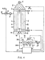
- FIG. 1 shows a two-beam gas analyzer with an infrared radiation source 1, the radiation of which is divided by a beam splitter 2 with a downstream light chopper 3 in the form of a rotating diaphragm wheel into a pulsating measuring beam 4 and a pulsating comparative beam 5.
- a measuring cuvette 6 is arranged, which can be filled via a pump 7 and controllable valves 8 either with a measuring gas 10 to be analyzed or with an inert gas 11 that does not absorb the radiation or for calibration with a calibration or calibration gas 12.
- the measuring beam 4 is pre-absorbed in the measuring cuvette 6.
- a comparison cuvette 13 in which a comparison gas, for. B. an inert gas is firmly enclosed.
- Both the measuring cuvette 6 and the comparison cuvette 13 are each followed by a gas-filled receiver chamber 14 or 15 for receiving the radiation emerging from the respective cuvette 6 or 13.
- the received pulsating radiation generates pressure fluctuations in the respective receiver chamber 14 or 15 by absorption, whereby these pressure fluctuations can differ depending on the pre-absorption in the measuring cell 6.
- Both receiver chambers 14 and 15 are connected to one another via a connecting line 16, in which a pressure or flow detector 17 for detecting the pressure differences between the two receiver chambers 14 and 15 or the gas flows caused thereby is arranged.
- the differential signal DS obtained in this way is weighted in a signal processing device 19, so that a measured value MW results at its output, which is displayed or recorded in a display or registration device 21.
- the differential signal DS is weighted in a device 22 shown here as an amplifier stage with a weighting factor K1 previously determined in a calibration or calibration process.
- a second device 23 located in the signal path, e.g. B. a second amplifier stage with a signal-weighting additional factor K2 is bridged by means of a controllable switching device 24.
- the balance of the radiation introduction into the measuring cuvette 6 and that can be adjusted mechanically by adjusting the radiation source 1 or the beam splitter 2 or by inserting an element 9 for beam limitation into the comparison beam path 5 Adjust comparison cell 13.
- the comparison beam 5 can be interrupted by a controllable diaphragm 26, the diaphragm 26, in contrast to the illustration in FIG. 1, also being arranged between the beam splitter 2 and the comparison cuvette 13 can be.
- control device 27 which also controls the valves 8 and the switching device 24 and the setting of the weighting factor K1 and the additional factor K2.
- the measuring cuvette 6 is flowed with a calibration or calibration gas, the calibration value of which, ie. H. the measured value MW to be displayed correctly is known.
- the weighting factor K1 is set by the controller 27 such that the measured value MW corresponds to the predetermined calibration value.
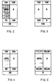
- This calibration process is illustrated schematically in FIG. 2 using a simple numerical example, in which radiation having the intensity value 100 is introduced into the measuring cuvette 6 and the comparative cuvette 13 by the arrangement of the radiation source 1 and the beam splitter 2.
- the known intensity weakening by the calibration or calibration gas in the measuring cell 6 is 30%, while the inert gas in the comparison cell 13 does not cause any intensity weakening.
- the measuring cuvette 6 is filled with an inert gas after the first calibration or calibration, and the beam path of the comparison beam 5 to the receiver chamber 15 is completely interrupted by means of the aperture 26. With switch 24 open, the additional factor K2 is now set so that the measured value MW again corresponds to the calibration value.
- the intensity value 100 is received in the receiver chamber 14 and the intensity value 0 is received in the receiver chamber 15 due to the interrupted comparison beam, so that the value 100 results for the difference signal DS.
- Operational analyzes of measurement gas are then carried out with the amplifier stage 23 bridged and the aperture 26 pushed out of the comparison beam path 5, the difference signal DS obtained being weighted with the weighting factor K1 to generate the measurement value MW.
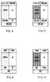
- FIG. 4 shows that, based on the numerical examples in FIGS. 2 and 3, there is a difference signal DS with the value 20 in the case of an intensity-related reduction in intensity of 20% in the measuring cell 6 filled with inert gas.
- This zero point deviation is introduced in accordance with FIG. 5 by changing the one introduced into the measuring cuvette 6 and the comparison cuvette 13 Radiation intensity compensated for 111.11 and 88.89.
- the comparison beam path 5 is interrupted with the aperture 26 and, with the switch 24 open at the same time, the weighting factor K1 is corrected such that the measured value MW again corresponds to the calibration value.
- the compensation of disturbance-related zero point deviations was carried out as part of the recalibration by readjusting the radiation source 1 or the beam splitter 2 or by means of the element 9.
- an alternative zero point adjustment is explained, which takes place exclusively in the context of the signal processing of the differential signal DS, so that the mechanical adjustment of elements of the two-beam gas analyzer is advantageously unnecessary.
- this zero point deviation is used as the offset value DS0 (FIG. 1) in the recalibration of the two-beam gas analyzer the control device 27 is stored.
- FIG. 9 shows this using the example of a measuring gas, which causes a reduction in the intensity of the measuring beam 4 by 40% in the measuring cell 6. Due to the additional 20% reduction in intensity due to interference, the intensity value 48 is received in the receiver chamber 14.
- the circuit blocks 21 ... 24 and 27 shown in FIG. 1 are primarily to be understood as function blocks, the functions of which can be implemented both by a hardware circuit and by program execution in a computing device.
- the adjustment of the radiation source 1, the beam splitter 2 or the element 9 indicated by the double arrow 25 also includes all other possible measures which can contribute to an adjustment of the radiation distribution to the measuring cuvette 6 and the comparison cuvette 13.
- the difference signal DS generally describes the difference between the radiation emerging from the measuring cell 6 and the radiation emerging from the comparison cell 13 and can also be generated differently than with the pressure or flow detector 17 shown, for example with radiation-sensitive semiconductor detectors.
Landscapes
- Physics & Mathematics (AREA)
- Spectroscopy & Molecular Physics (AREA)
- Analytical Chemistry (AREA)
- Biochemistry (AREA)
- Pathology (AREA)
- Health & Medical Sciences (AREA)
- Life Sciences & Earth Sciences (AREA)
- Chemical & Material Sciences (AREA)
- Immunology (AREA)
- General Physics & Mathematics (AREA)
- General Health & Medical Sciences (AREA)
- Theoretical Computer Science (AREA)
- Engineering & Computer Science (AREA)
- Mathematical Physics (AREA)
- Investigating Or Analysing Materials By Optical Means (AREA)
- Sampling And Sample Adjustment (AREA)
Applications Claiming Priority (2)
| Application Number | Priority Date | Filing Date | Title |
|---|---|---|---|
| DE19547787A DE19547787C1 (de) | 1995-12-20 | 1995-12-20 | Zweistrahl-Gasanalysator und Verfahren zu seiner Kalibrierung |
| DE19547787 | 1995-12-20 |
Publications (3)
| Publication Number | Publication Date |
|---|---|
| EP0780681A2 true EP0780681A2 (fr) | 1997-06-25 |
| EP0780681A3 EP0780681A3 (fr) | 1998-05-06 |
| EP0780681B1 EP0780681B1 (fr) | 2007-09-05 |
Family
ID=7780790
Family Applications (1)
| Application Number | Title | Priority Date | Filing Date |
|---|---|---|---|
| EP96118910A Expired - Lifetime EP0780681B1 (fr) | 1995-12-20 | 1996-11-26 | Analyseur de gaz à deux faisceaux et procédé pour son étalonnage |
Country Status (4)
| Country | Link |
|---|---|
| US (1) | US5764354A (fr) |
| EP (1) | EP0780681B1 (fr) |
| AT (1) | ATE372511T1 (fr) |
| DE (2) | DE19547787C1 (fr) |
Cited By (3)
| Publication number | Priority date | Publication date | Assignee | Title |
|---|---|---|---|---|
| DE19926121C2 (de) * | 1999-06-08 | 2001-10-18 | Cs Halbleiter Solartech | Analysegerät |
| EP1640708A1 (fr) * | 2004-09-25 | 2006-03-29 | Maihak Ag | Analyseur de gaz à deux faisceaux |
| DE102012216210A1 (de) | 2012-09-12 | 2014-01-30 | Siemens Aktiengesellschaft | Nichtdispersiver Infrarot-Gasanalysator nach dem Zweistrahlverfahren |
Families Citing this family (17)
| Publication number | Priority date | Publication date | Assignee | Title |
|---|---|---|---|---|
| DE19810483A1 (de) * | 1998-03-11 | 1999-09-23 | Bosch Gmbh Robert | Verfahren zur Bestimmung des Sensor-Offsets bei HC- und/oder NOx-Sensoren |
| DE19924544A1 (de) * | 1998-05-29 | 1999-12-02 | Horiba Ltd | Detektor zur Anwendung in einem Infrarotanalysator, Durchflußdetektor und Verfahren zur Herstellung desselben |
| FR2811761B1 (fr) * | 2000-07-17 | 2002-10-11 | Production Rech S Appliquees | Ellipsometre a haute resolution spatiale fonctionnant dans l'infrarouge |
| US20050185176A1 (en) * | 2004-02-23 | 2005-08-25 | Moran Donald J.Jr. | Determining an analyte by multiple measurements through a cuvette |
| US7307718B2 (en) * | 2004-02-23 | 2007-12-11 | Ortho-Clinical Diagnostics, Inc. | Determining an analyte by multiple measurements through a cuvette |
| JP4411599B2 (ja) * | 2004-10-26 | 2010-02-10 | 横河電機株式会社 | 赤外線ガス分析計および赤外線ガス分析方法 |
| DE102004055741B4 (de) * | 2004-11-18 | 2007-03-15 | Siemens Ag | Nichtdispersiver Infrarot-Gasanalysator nach dem Zweistrahl-Prinzip |
| CN100494983C (zh) * | 2005-08-12 | 2009-06-03 | 深圳迈瑞生物医疗电子股份有限公司 | 利用红外光吸收特性自动校准和测量气体浓度的方法和装置 |
| US8158945B2 (en) * | 2007-05-02 | 2012-04-17 | Siemens Aktiengesellschaft | Detector arrangement for a nondispersive infrared gas analyzer and method for the detection of a measuring gas component in a gas mixture by means of such a gas analyzer |
| WO2010120821A1 (fr) * | 2009-04-14 | 2010-10-21 | Airware, Inc. | Méthodologie de détection de gaz non dispersif dans l'infrarouge par filtrage de saturation |
| DE102009017932B4 (de) | 2009-04-20 | 2010-12-09 | Gröger & Obst Vertriebs- und Service GmbH | Verfahren zur kontinuierlichen quantitativen Bestimmung einer oxidierbaren chemischen Verbindung in einem Untersuchungsmedium |
| DE102009021829A1 (de) | 2009-05-19 | 2010-11-25 | Siemens Aktiengesellschaft | NDIR-Zweistrahl-Gasanalysator und Verfahren zur Bestimmung der Konzentration einer Messgaskomponente in einem Gasgemisch mittels eines solchen Gasanalysators |
| DE102009059962B4 (de) | 2009-12-22 | 2011-09-01 | Siemens Aktiengesellschaft | NDIR-Zweistrahl-Gasanalysator und Verfahren zur Bestimmung der Konzentration einer Messgaskomponente in einem Gasgemisch mittels eines solchen Gasanalysators |
| US8358417B2 (en) * | 2010-10-21 | 2013-01-22 | Spectrasensors, Inc. | Spectrometer with validation cell |
| US9435687B1 (en) * | 2014-04-02 | 2016-09-06 | Center For Quantitative Cytometry | Method to remove the spectral components of illumination energy from a sample spectrum without the use of optical barrier filters, and apparatus for the same |
| AT521624B1 (de) * | 2019-01-17 | 2020-03-15 | Scan Messtechnik Gmbh | Vorrichtung und Verfahren zum Erfassen von Eigenschaften eines zu untersuchenden Fluids |
| DE102023107812A1 (de) * | 2023-03-28 | 2024-10-02 | Inficon Gmbh | Strahlungsabsorptions-Gasanalysator und Verfahren zur Gasanalyse |
Citations (1)
| Publication number | Priority date | Publication date | Assignee | Title |
|---|---|---|---|---|
| EP0199365A2 (fr) | 1985-04-26 | 1986-10-29 | Hartmann & Braun Aktiengesellschaft | Analyseur de gaz par infrarouge |
Family Cites Families (16)
| Publication number | Priority date | Publication date | Assignee | Title |
|---|---|---|---|---|
| DE1082433B (de) * | 1958-08-20 | 1960-05-25 | Hartmann & Braun Ag | Anordnung zur Eichung von Gasanalysegeraeten, die auf dem Prinzip der Absorption infraroter Strahlung beruhen |
| US3560736A (en) * | 1968-10-09 | 1971-02-02 | Mine Safety Appliances Co | Non-dispersive infrared gas analyzer with unbalanced operation |
| DE2042727B2 (de) * | 1970-08-28 | 1974-03-21 | Siemens Ag, 1000 Berlin U. 8000 Muenchen | Justiereinrichtung für ein Infrarot-Gasanalysegerät |
| DE2359637C2 (de) * | 1973-11-30 | 1982-08-26 | Hartmann & Braun Ag, 6000 Frankfurt | Nichtdispersives Ultrarot-Gasanalysengerät |
| US4010368A (en) * | 1974-04-23 | 1977-03-01 | Autoscan, Inc. | Test apparatus |
| DE2614181C3 (de) * | 1976-04-02 | 1981-08-20 | Leybold-Heraeus Gmbh, 5000 Koeln | Verfahren zur Messung des optischen Absorptionsvermögens von Proben und Vorrichtung zur Durchführung des Verfahrens |
| DE2638522C3 (de) * | 1976-08-26 | 1979-12-13 | Siemens Ag, 1000 Berlin Und 8000 Muenchen | Nichtdispersiver Zweistrahl-Infrarot-Gasanalysator mit je einem Doppelschichtempfänger im Meß- und Vergleichsstrahlengang |
| DE2639210C2 (de) * | 1976-08-31 | 1985-09-26 | Siemens AG, 1000 Berlin und 8000 München | Nichtdispersiver Infrarot-Gasanalysator nach dem Zweistrahlverfahren |
| DD234493B1 (de) * | 1985-02-01 | 1989-01-18 | Junkalor Dessau | Anordnung zur nachkalibrierung von nichtdispersiven infrarot-gasanalysatoren |
| DE3522949A1 (de) * | 1985-06-27 | 1987-01-08 | Hartmann & Braun Ag | Verfahren zum nachjustieren von infrarot-gasanalysatoren |
| US4694174A (en) * | 1985-10-01 | 1987-09-15 | Gas Alarm Service, Inc. | Infrared gas detector |
| JPS62126329A (ja) * | 1985-11-27 | 1987-06-08 | Horiba Ltd | 吸光分析計 |
| DE3932838C2 (de) * | 1989-09-30 | 1996-03-07 | Hartmann & Braun Ag | Nichtdispersiver Infrarot-Gasanalysator |
| DE4111187C2 (de) * | 1991-04-06 | 1994-11-24 | Lfe Lab Fuer Ind Forschung Gmb | Verfahren zur Messung des optischen Absorptionsvermögens von Proben unter Eliminierung des Anzeigefehlers hinsichtlich gas-physikalischer Eigenschaften und Vorrichtung zur Durchführung des Verfahrens |
| DE4432940C2 (de) * | 1993-09-24 | 1997-10-02 | Fuji Electric Co Ltd | Infrarot-Gasanalysator |
| JPH07140075A (ja) * | 1993-09-24 | 1995-06-02 | Fuji Electric Co Ltd | 赤外線ガス分析計 |
-
1995
- 1995-12-20 DE DE19547787A patent/DE19547787C1/de not_active Expired - Fee Related
-
1996
- 1996-11-26 DE DE59611442T patent/DE59611442D1/de not_active Expired - Lifetime
- 1996-11-26 AT AT96118910T patent/ATE372511T1/de active
- 1996-11-26 EP EP96118910A patent/EP0780681B1/fr not_active Expired - Lifetime
- 1996-12-20 US US08/772,201 patent/US5764354A/en not_active Expired - Lifetime
Patent Citations (1)
| Publication number | Priority date | Publication date | Assignee | Title |
|---|---|---|---|---|
| EP0199365A2 (fr) | 1985-04-26 | 1986-10-29 | Hartmann & Braun Aktiengesellschaft | Analyseur de gaz par infrarouge |
Cited By (4)
| Publication number | Priority date | Publication date | Assignee | Title |
|---|---|---|---|---|
| DE19926121C2 (de) * | 1999-06-08 | 2001-10-18 | Cs Halbleiter Solartech | Analysegerät |
| US6762410B1 (en) | 1999-06-08 | 2004-07-13 | Cs Clean Systems Ag | Analysis apparatus |
| EP1640708A1 (fr) * | 2004-09-25 | 2006-03-29 | Maihak Ag | Analyseur de gaz à deux faisceaux |
| DE102012216210A1 (de) | 2012-09-12 | 2014-01-30 | Siemens Aktiengesellschaft | Nichtdispersiver Infrarot-Gasanalysator nach dem Zweistrahlverfahren |
Also Published As
| Publication number | Publication date |
|---|---|
| US5764354A (en) | 1998-06-09 |
| DE59611442D1 (de) | 2007-10-18 |
| EP0780681B1 (fr) | 2007-09-05 |
| DE19547787C1 (de) | 1997-04-17 |
| ATE372511T1 (de) | 2007-09-15 |
| EP0780681A3 (fr) | 1998-05-06 |
Similar Documents
| Publication | Publication Date | Title |
|---|---|---|
| EP0780681B1 (fr) | Analyseur de gaz à deux faisceaux et procédé pour son étalonnage | |
| DE3932838C2 (de) | Nichtdispersiver Infrarot-Gasanalysator | |
| DE102009021829A1 (de) | NDIR-Zweistrahl-Gasanalysator und Verfahren zur Bestimmung der Konzentration einer Messgaskomponente in einem Gasgemisch mittels eines solchen Gasanalysators | |
| EP2240760B1 (fr) | Analyseur de gaz à infrarouge non dispersif | |
| EP2142909B1 (fr) | Système de détecteur pour analyseur de gaz à infrarouge non dispersif et procédé de détection d'un composant gazeux à mesurer dans un mélange de gaz au moyen d'un tel analyseur de gaz | |
| DE102009059962B4 (de) | NDIR-Zweistrahl-Gasanalysator und Verfahren zur Bestimmung der Konzentration einer Messgaskomponente in einem Gasgemisch mittels eines solchen Gasanalysators | |
| DE3524368A1 (de) | Infrarot-gasanalysator mit kalibriereinrichtung | |
| DE3524189C2 (de) | Infrarot-Gasanalysator | |
| DE3023625A1 (de) | System zur ueberwachung der konzentration eines spezifischen gases in einer (umwelt) probe | |
| DE2015694B2 (de) | Verfahren zur beruehrungslosen messung der breite oder lage eines gegenstandes mittels eines sichtstrahls | |
| DE4111187C2 (de) | Verfahren zur Messung des optischen Absorptionsvermögens von Proben unter Eliminierung des Anzeigefehlers hinsichtlich gas-physikalischer Eigenschaften und Vorrichtung zur Durchführung des Verfahrens | |
| DE2359637C2 (de) | Nichtdispersives Ultrarot-Gasanalysengerät | |
| EP2551662B1 (fr) | Installation optique d'analyse de gaz avec des agents destinés à améliorer la sélectivité lors des analyses de mélanges de gaz | |
| DE3116344A1 (de) | Verfahren zum erhoehen der messgenauigkeit eines gasanalysators | |
| DE3402800A1 (de) | Nach dem gasfilterkorrelationsverfahren arbeitendes fotometer | |
| DE1065637B (de) | Absorptions - Meßanordnung, insbesondere Gasanalysator zum Vergleich zweier Konzentrationen | |
| DE3940141A1 (de) | Verfahren zur direkten, messtechnischen darstellung einer differenzmessgroesse in ihrer korrekten physikalischen einheit | |
| DE3883442T2 (de) | Gasanalysator. | |
| EP0197917A2 (fr) | Procédé pour la détermination périodique d'une grandeur mesurable et dispositif pour la mise en oeuvre du procédé | |
| DE19518322C1 (de) | Absorptionsphotometer | |
| DE102005008042A1 (de) | Einrichtung und Verfahren zur Kalibrierung der Empfindlichkeit eines Fotometers | |
| DE3830834C2 (fr) | ||
| DD159367A1 (de) | Modulationseinrichtung in einem nicht dispersiven analysengeraet | |
| EP3575759B1 (fr) | Spectromètre et son procédé de fonctionnement | |
| EP0657731B1 (fr) | Procédé et appareil pour déterminer une absorption caractéristique d'une substance |
Legal Events
| Date | Code | Title | Description |
|---|---|---|---|
| PUAI | Public reference made under article 153(3) epc to a published international application that has entered the european phase |
Free format text: ORIGINAL CODE: 0009012 |
|
| 17P | Request for examination filed |
Effective date: 19961204 |
|
| AK | Designated contracting states |
Kind code of ref document: A2 Designated state(s): AT CH DE FR GB IT LI |
|
| PUAL | Search report despatched |
Free format text: ORIGINAL CODE: 0009013 |
|
| AK | Designated contracting states |
Kind code of ref document: A3 Designated state(s): AT CH DE FR GB IT LI |
|
| 17Q | First examination report despatched |
Effective date: 20061004 |
|
| GRAP | Despatch of communication of intention to grant a patent |
Free format text: ORIGINAL CODE: EPIDOSNIGR1 |
|
| RIC1 | Information provided on ipc code assigned before grant |
Ipc: G01N 21/37 20060101AFI20070307BHEP |
|
| GRAS | Grant fee paid |
Free format text: ORIGINAL CODE: EPIDOSNIGR3 |
|
| GRAA | (expected) grant |
Free format text: ORIGINAL CODE: 0009210 |
|
| AK | Designated contracting states |
Kind code of ref document: B1 Designated state(s): AT CH DE FR GB IT LI |
|
| REG | Reference to a national code |
Ref country code: GB Ref legal event code: FG4D Free format text: NOT ENGLISH |
|
| REG | Reference to a national code |
Ref country code: CH Ref legal event code: NV Representative=s name: SIEMENS SCHWEIZ AG Ref country code: CH Ref legal event code: EP |
|
| GBT | Gb: translation of ep patent filed (gb section 77(6)(a)/1977) |
Effective date: 20070911 |
|
| REF | Corresponds to: |
Ref document number: 59611442 Country of ref document: DE Date of ref document: 20071018 Kind code of ref document: P |
|
| ET | Fr: translation filed | ||
| PLBE | No opposition filed within time limit |
Free format text: ORIGINAL CODE: 0009261 |
|
| STAA | Information on the status of an ep patent application or granted ep patent |
Free format text: STATUS: NO OPPOSITION FILED WITHIN TIME LIMIT |
|
| 26N | No opposition filed |
Effective date: 20080606 |
|
| REG | Reference to a national code |
Ref country code: CH Ref legal event code: PCAR Free format text: SIEMENS SCHWEIZ AG;INTELLECTUAL PROPERTY FREILAGERSTRASSE 40;8047 ZUERICH (CH) |
|
| PGFP | Annual fee paid to national office [announced via postgrant information from national office to epo] |
Ref country code: CH Payment date: 20120206 Year of fee payment: 16 |
|
| PGFP | Annual fee paid to national office [announced via postgrant information from national office to epo] |
Ref country code: GB Payment date: 20121115 Year of fee payment: 17 Ref country code: IT Payment date: 20121129 Year of fee payment: 17 |
|
| PGFP | Annual fee paid to national office [announced via postgrant information from national office to epo] |
Ref country code: FR Payment date: 20121214 Year of fee payment: 17 Ref country code: AT Payment date: 20121010 Year of fee payment: 17 |
|
| PGFP | Annual fee paid to national office [announced via postgrant information from national office to epo] |
Ref country code: DE Payment date: 20130118 Year of fee payment: 17 |
|
| REG | Reference to a national code |
Ref country code: CH Ref legal event code: PL |
|
| PG25 | Lapsed in a contracting state [announced via postgrant information from national office to epo] |
Ref country code: LI Free format text: LAPSE BECAUSE OF NON-PAYMENT OF DUE FEES Effective date: 20121130 Ref country code: CH Free format text: LAPSE BECAUSE OF NON-PAYMENT OF DUE FEES Effective date: 20121130 |
|
| REG | Reference to a national code |
Ref country code: AT Ref legal event code: MM01 Ref document number: 372511 Country of ref document: AT Kind code of ref document: T Effective date: 20131126 |
|
| GBPC | Gb: european patent ceased through non-payment of renewal fee |
Effective date: 20131126 |
|
| REG | Reference to a national code |
Ref country code: FR Ref legal event code: ST Effective date: 20140731 |
|
| REG | Reference to a national code |
Ref country code: DE Ref legal event code: R119 Ref document number: 59611442 Country of ref document: DE Effective date: 20140603 |
|
| PG25 | Lapsed in a contracting state [announced via postgrant information from national office to epo] |
Ref country code: DE Free format text: LAPSE BECAUSE OF NON-PAYMENT OF DUE FEES Effective date: 20140603 Ref country code: AT Free format text: LAPSE BECAUSE OF NON-PAYMENT OF DUE FEES Effective date: 20131126 Ref country code: IT Free format text: LAPSE BECAUSE OF NON-PAYMENT OF DUE FEES Effective date: 20131126 |
|
| PG25 | Lapsed in a contracting state [announced via postgrant information from national office to epo] |
Ref country code: FR Free format text: LAPSE BECAUSE OF NON-PAYMENT OF DUE FEES Effective date: 20131202 Ref country code: GB Free format text: LAPSE BECAUSE OF NON-PAYMENT OF DUE FEES Effective date: 20131126 |